Oddly shaped holes?
-
@Coffee said in Oddly shaped holes?:
Tinkering can lead to your hands/fingers lookin' like ya washed 'em with barbed wire.
100 days tinkering == 1 hour playing with a young cat

-
@arhi said in Oddly shaped holes?:
One suggestion: Remove extruder and mount technical pen and instead of printing write on paper until you solve the circle issue.
Ideally instead of pen using a ballbar would be awesome but who has ballbard these days ( https://resources.renishaw.com/en/download/white-paper-ballbar-testing-with-circle-diamond-square-machining-tests--99016 )
look at this: https://sphereinabox.wordpress.com/2014/07/19/delta-actuator-math-notes/
see the first picture, looks like your problem
write your own g-code and test it with a technical pen, no need to waste plastic and introduce another axis into mix
")
also check out
https://www.thingiverse.com/thing:3060573finally, marlin have support for some backlash testing procedure
M425 - Backlash compensation
I never used it, maybe RRF have something similar, maybe just reading about what they do help you do it manually yourself..So, according to that picture, I have backlash in my Y axis, which I thought. I'm pretty sure it's "sticktion", just from watching it and moving the gantry by hand. My options are to either get rid of the igus bushings, or try to re-square the gantry because for some reason it's not square. I'm going to order some LM16UU just in case. Probably the last time I use igus stuff. It's been a nightmare. I just wanted to make the printer quieter.
-
I had very nice experience with igus, I used their aluminium rods and their bushings that I pressed in printed blocks... used that on some i3 style printer and apart from being quiet all the ringing was gone
-
@arhi I pressed them into these blocks. Maybe they're too tight? I'm really not sure.
-
@Surgikill when they are too tight they slide harder so your motor needs to work harder and can skip steps for a while, then they "ware out" and slide perfectly, no way they can introduce slop if they are too tight in my opinion. Only issue is if they are too loose.
-
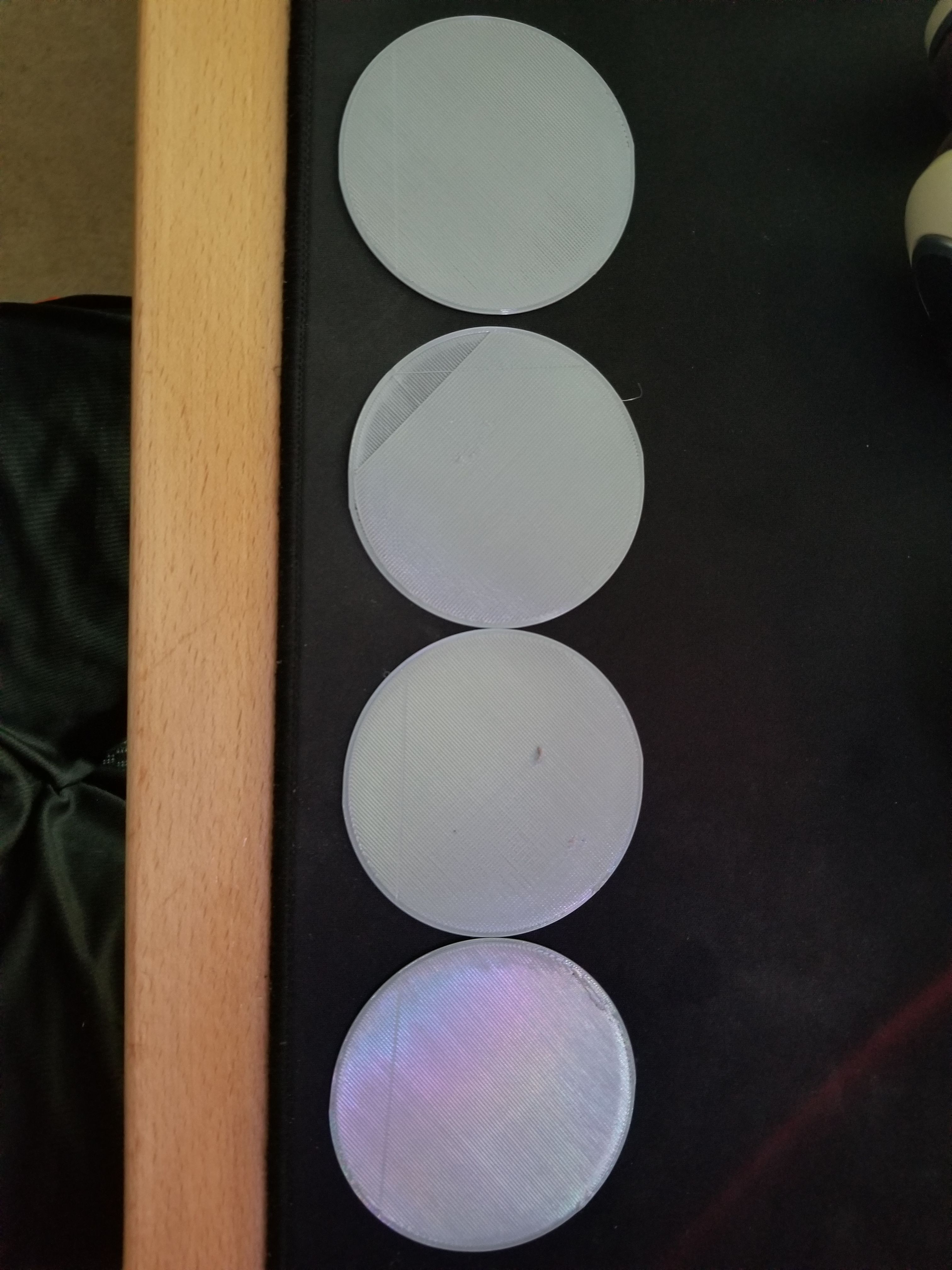
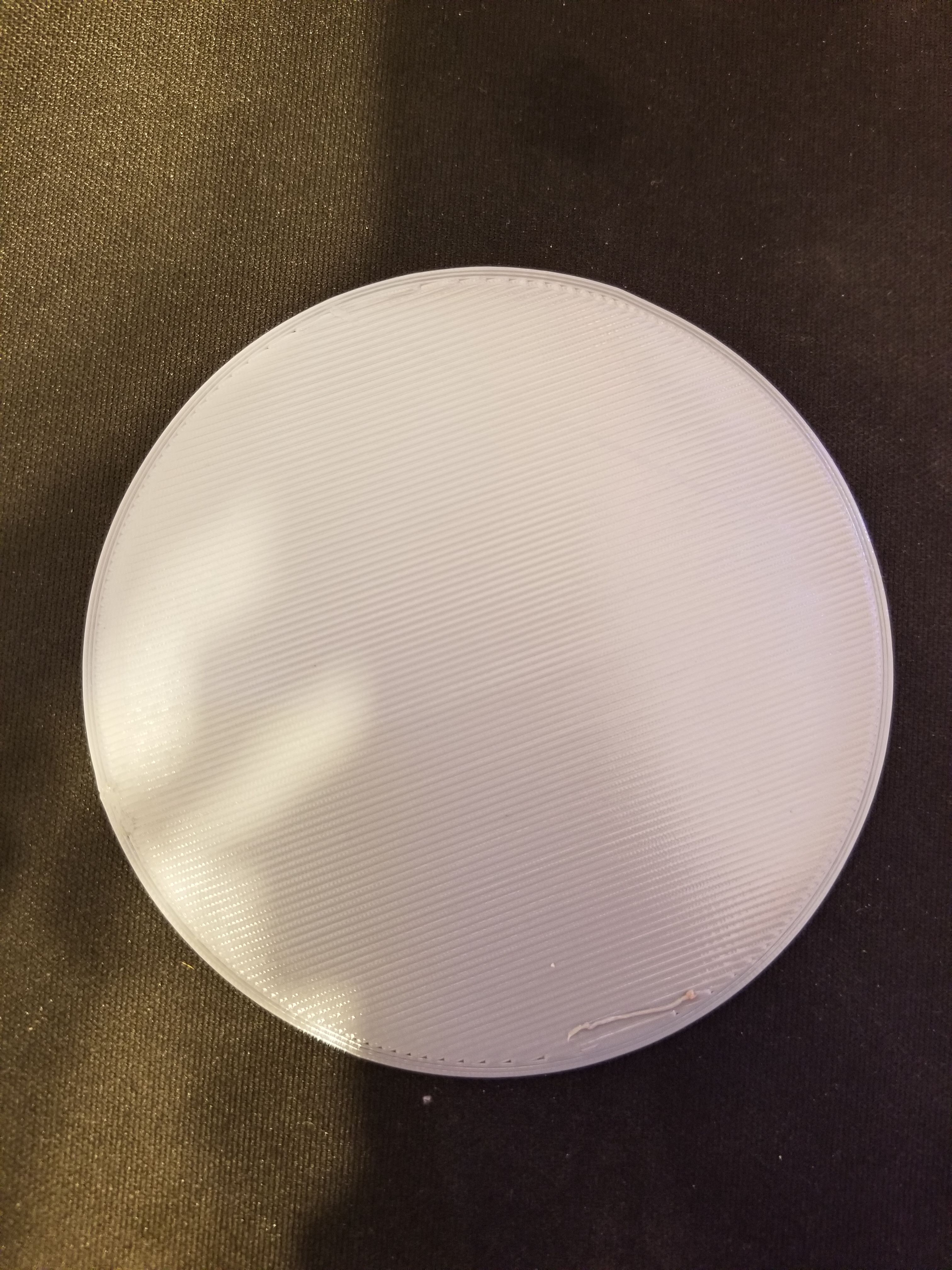
@arhi Here's the latest test piece. It definitely looks butter, but it's still sticking. Not sure how long these bushings need to "wear in" but I've probably put over 20-25 hours on them so far, so they should be pretty worn in.
I have to do a bunch of BS to remove the extruder. I might be able to tape a pen to the side and then try and manually home it.
I ordered some regular LM16UU bearings. I'd really like to get this figured out with the bushings if possible though. They are definitely quieter and provide smoother operation.


-
@Surgikill said in Oddly shaped holes?:
@arhi Here's the latest test piece. It definitely looks butter, but it's still sticking. Not sure how long these bushings need to "wear in" but I've probably put over 20-25 hours on them so far, so they should be pretty worn in.
As long as they are not slopy they are IMO not part of this problem.
I have to do a bunch of BS to remove the extruder. I might be able to tape a pen to the side and then try and manually home it.
tape a pen
hotglue a pen... something like that .. or do a single layer print with extruder but pen is much faster, no need to wait for anything to heat up I ordered some regular LM16UU bearings. I'd really like to get this figured out with the bushings if possible though. They are definitely quieter and provide smoother operation.
If the bushings are not showing slop it's not up to them I'm sure
as I said, start writing some manual gcode to see where the problem is ..
you say if you move in diagonal only one motor motor moves .. so test something like
; add here your temperature stuff for bed and extruder, your normal start code ; do the test M83 ; RELATIVE extruder move G0X0Y20Z0.25 ; go to start position, 0.25mm layer G0X10Y10 G1X50Y50F600E2.352 G1X80Y10F600E2.352 G1X100Y30F600E1.176 G1X70Y70F600E2.352 G1X50Y50F600E1.176 G0Z20 ; turn off your bed and extruder heaters now all moves should be single motor only, and last move should hit exactly the 50,50 coordinate that first move ends at but from different
-
@arhi said in Oddly shaped holes?:
@Surgikill said in Oddly shaped holes?:
@arhi Here's the latest test piece. It definitely looks butter, but it's still sticking. Not sure how long these bushings need to "wear in" but I've probably put over 20-25 hours on them so far, so they should be pretty worn in.
As long as they are not slopy they are IMO not part of this problem.
I don't think it's slop that's the issue. I think they are sticking. It seems to happen more towards the extreme y axis.
as I said, start writing some manual gcode to see where the problem is ..
you say if you move in diagonal only one motor motor moves .. so test something like
; add here your temperature stuff for bed and extruder, your normal start code ; do the test M83 ; RELATIVE extruder move G0X0Y20Z0.25 ; go to start position, 0.25mm layer G0X10Y10 G1X50Y50F600E2.352 G1X80Y10F600E2.352 G1X100Y30F600E1.176 G1X70Y70F600E2.352 G1X50Y50F600E1.176 G0Z20 ; turn off your bed and extruder heaters now all moves should be single motor only, and last move should hit exactly the 50,50 coordinate that first move ends at but from different
I'm pretty bad with gcode. What is that drawing exactly? A box? I'll make it up and see what happens.
-
@Surgikill said in Oddly shaped holes?:
I don't think it's slop that's the issue. I think they are sticking. It seems to happen more towards the extreme y axis.
If they are binding then you have skipped steps, but possible they are binding in a way that for microstepping you are inprecise.
There is a super simple test for that, turn off interpolation as set microstepping to 2 (half step only), and reduce your step/mm for XY 8 times (if you are at 1/16 now) .. the movement will be jerky and circle will be "stepped" and not smooth but should be circle, not that thing you have now.
I'm pretty bad with gcode. What is that drawing exactly? A box? I'll make it up and see what happens.
if you plan on doing a lot of 3d printing, learn it
it's rather simple
it moves your head "to some coordinate" soif you follow the gcode
go to 0,20 then to 10,10, then to 50,50, then to 80,10 -> 100,30 ->70,70 -> 50,50 and finally go to Z20 (raise head or drop table whatever moves in your case)
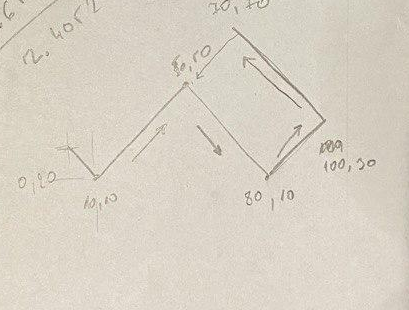
so if you look at 50,50 point, extruder will in first arrive there from 10,10 but coming from "above" from 0,20, then it will change direction coming from 100,30 to 70,70 so when it returns to 50,50 it will be misaligned for the backlash in one of two motors.
You can't make this as "object" as you don't have control in slicer of the direction of the travel, these type of g-codes you have to write yourself to test stuff you want to test... you should then make a mirror of this move to test the other motor (assuming I guessed right the single motor movement on coreXY as I said, zero experience in that department)
BTW if you lock your motors, any direction you can move your head for a fraction of mm ?
-
@arhi said in Oddly shaped holes?:
@Surgikill said in Oddly shaped holes?:
I don't think it's slop that's the issue. I think they are sticking. It seems to happen more towards the extreme y axis.
If they are binding then you have skipped steps, but possible they are binding in a way that for microstepping you are inprecise.
There is a super simple test for that, turn off interpolation as set microstepping to 2 (half step only), and reduce your step/mm for XY 8 times (if you are at 1/16 now) .. the movement will be jerky and circle will be "stepped" and not smooth but should be circle, not that thing you have now.
I'm pretty bad with gcode. What is that drawing exactly? A box? I'll make it up and see what happens.
if you plan on doing a lot of 3d printing, learn it
it's rather simple
it moves your head "to some coordinate" soif you follow the gcode
go to 0,20 then to 10,10, then to 50,50, then to 80,10 -> 100,30 ->70,70 -> 50,50 and finally go to Z20 (raise head or drop table whatever moves in your case)
so if you look at 50,50 point, extruder will in first arrive there from 10,10 but coming from "above" from 0,20, then it will change direction coming from 100,30 to 70,70 so when it returns to 50,50 it will be misaligned for the backlash in one of two motors.
You can't make this as "object" as you don't have control in slicer of the direction of the travel, these type of g-codes you have to write yourself to test stuff you want to test... you should then make a mirror of this move to test the other motor (assuming I guessed right the single motor movement on coreXY as I said, zero experience in that department)
BTW if you lock your motors, any direction you can move your head for a fraction of mm ?
Yea I just wrote that gcode out and it did nada. It didn't even extrude any filament. I'm going to mess with it and see what I can do.
EDIT: Yea I have no idea what it's trying to do, but it's air printing and not extruding anything. I'm just going to try and make a thin wall part and try it.
-
@Surgikill said in Oddly shaped holes?:
Yea I have no idea what it's trying to do, but it's air printing and not extruding anything.
you need to add the start code before it (heat your bed, then heat your nozzle, then home.... ) as it will print in the air if it's not homed and will not extrude if it's cold
I just put the "action" part in, the rest depends on your printer.
I'm just going to try and make a thin wall part and try it.
problem with that is that you don't know what side the slicer with make the path come from
-
@arhi I did all of that. I took start and end gcode I have for my slicer and pasted it in there. Not sure what the issue is. I changed the F value as well because I think it was a little too low. I had 1800 in my setup.
-
@Surgikill I used 10mm/sec as "safe"
.. you can increase .. you can try to increase the E values, maybe I was too conservative and put too low valuesbut it can't be printing in air
the first line after M83 (M83 just set extruder to relative positioning) is
G0X0Y20Z0.25
that's move (G0) to X=0 (X0) Y=20 (Y20) and Z=0.25 (Z0.25)
Z is not set after that so all moves here needs to be on Z=0.25mm
till the last code G0Z20 that moves Z straight up 20mm
The E value is maybe to low and maybe you need to prime it first, something like this:
;bed temp, extruder temp, home.. M190 S60 ; bed 60 M109 S230 ; nozzle 230 M106 S0 ; fan off G28 ; home ;... G21 ; millimeters G90 ; absolute XY moves M83 ; RELATIVE extruder move M200 D0 ; no volumetric extrusion G0X0Y0Z10 ; go to 0,0,10 G1E50F100 ; extrude a blob of plastic in the air to prime the nozzle G1X0Y20Z0.25 ; go to start position, 0.25mm layer G1X10Y10 G1X50Y50F600E2.352 G1X80Y10F600E2.352 G1X100Y30F600E1.176 G1X70Y70F600E2.352 G1X50Y50F600E1.176 G0Z20 M104 S0 ; turn off extruder M140 S0 ; turn off bed M106 S0 ; turn off fan ;... ; shut everything down here -
@arhi This is the start of one of my gcode files. I forget exactly what I had to do, but I think I wrote something special in there because I'm using 4 independent z motors to tram the bed.
M107 M107 M104 S235 ; set temperature G32 ;home and level G28 ;home G21 ; set units to millimeters G90 ; use absolute coordinates M82 ; use absolute distances for extrusion G92 E0 ; Filament gcode M109 S235 ; set temperature and wait for it to be reached G21 ; set units to millimeters G90 ; use absolute coordinates M82 ; use absolute distances for extrusion G92 E0 G1 Z0.200 F7800.000 G1 E-2.00000 F2400.00000 G92 E0 G1 Z0.350 F7800.000 G1 E-2.00000 F2400.00000 G92 E0 G1 X91.390 Y102.905 F7800.000 G1 E2.00000 F2400.00000 G1 F1800.000 G1 X93.026 Y102.689 E2.11451 G1 X117.999 Y102.489 E3.84808 G1 X179.410 Y102.488 E8.11097 G1 X207.724 Y102.689 E10.07646 G1 X208.948 Y102.812 E10.16187 G1 X209.906 Y103.069 E10.23068 G1 X210.823 Y103.463 E10.29994 G1 X211.673 Y103.985 E10.36920 G1 X212.434 Y104.621 E10.43802 G1 X213.273 Y105.598 E10.52746 G1 X215.387 Y108.621 E10.78349 G1 X215.889 Y109.505 E10.85410 I'm going to try adding your code in with the prime on the extruder. I usually use a skirt, so that's my priming.
-
@arhi Yea I just ran the updated Gcode and it's still printing in air and not extruding anything. This is what I have for the gcode.
M107 M107 M104 S235 ; set temperature G32 ;home and level G28 ;home G21 ; set units to millimeters G90 ; use absolute coordinates M82 ; use absolute distances for extrusion G92 E0 ; Filament gcode M109 S235 ; set temperature and wait for it to be reached G21 ; set units to millimeters G90 ; use absolute coordinates M82 ; use absolute distances for extrusion G92 E0 G1 Z0.200 F7800.000 G1 E-2.00000 F2400.00000 G92 E0 G1 Z0.350 F7800.000 G1 E-2.00000 F2400.00000 G92 E0 G1 X91.390 Y102.905 F7800.000 G1 E2.00000 F2400.00000 G1 F1800.000 ;... G21 ; millimeters G90 ; absolute XY moves M83 ; RELATIVE extruder move M200 D0 ; no volumetric extrusion G0X0Y0Z10 ; go to 0,0,10 G1E50F100 ; extrude a blob of plastic in the air to prime the nozzle G1X0Y20Z0.25 ; go to start position, 0.25mm layer G1X10Y10 G1X50Y50F600E2.352 G1X80Y10F600E2.352 G1X100Y30F600E1.176 G1X70Y70F600E2.352 G1X50Y50F600E1.176 G0Z20 ;... ; shut everything down here G92 E0 M107 ; Filament-specific end gcode ;END gcode for filament M104 S0 ; turn off hotend M140 S0 ; turn off bed G28 X0 Y0 ; home X axis G1 Z310 ;move Z to max M84 ; disable motors -
@Surgikill said in Oddly shaped holes?:
still printing in air and not extruding anything
the extrusion, you can try increasing the E values in those codes
but "in the air" .. no idea, it must be at z 0.25 .. that is very close to table .. no clue how it messes up -
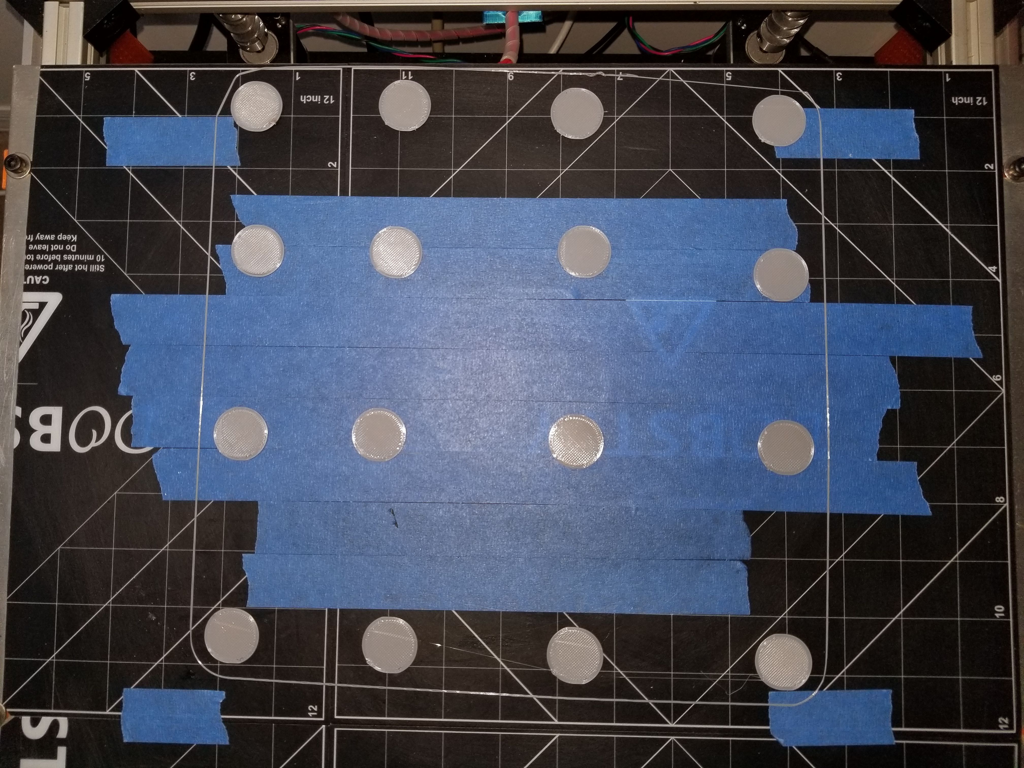
@arhi This might help. The circles on the bottom of the picture are closest to Y max, and the circles at the top of the picture are closes to Y min. X min is right side, X max is left side. It definitely look like the circles get worse as it goes towards Y max.

-
Sorry mate, I'm lost here. You really need someone who actually has experience with coreXY machine. With the CNC this type of error is always backlash. No clue how backlash on each motor affect this at all. Normally you can tweak backlash compensation in the firmware of your CNC machine, but AFAIK there is no support for that in RRF (not sure any 3d printing firmware supports it, I know there was try to implement it in marlin but I think they gave up, never entered master branch).
-
@arhi My theory here is that the igus bushings are binding up near Y max. This is causing 2 things:
- I lose microstepping, which causes a loss in resolution
- My belts stretch more (it's a pretty large printer, so the belts are pretty long) and that creates the "backlash" issue
I'll have the LM16UU bearings in this coming week. Those will get installed and hopefully this issue will be resolved.
-
It is a good theory as any. I see even on large printers ppl go with 2mm belts which is weird to me, the only reason to go with 2mm pitch is tight bend radius, but if you are on big printer you can design so that you don't need tight bend radius and go with 5mm pitch where for much less $$ you can get higher quality belts .. but ..