Vertical Hole Compression: Possible Solution
-
@mrehorstdmd said in Vertical Hole Compression: Possible Solution:
If I'm printing something where I need accurate alignment between bearings I print it so that the holes for the bearings are printed in the XY plane. I know it isn't possible with all prints to do that, but you'll definitely get best alignment and fit that way. If the part has other areas that need accurate alignment as well, I will typically split it into multiple pieces so that all of them get the better alignment assured by printing in the XY plane. It's not cheating to make printed things out of multiple parts!
Recent motor mount with a bearing on the end of the shaft:
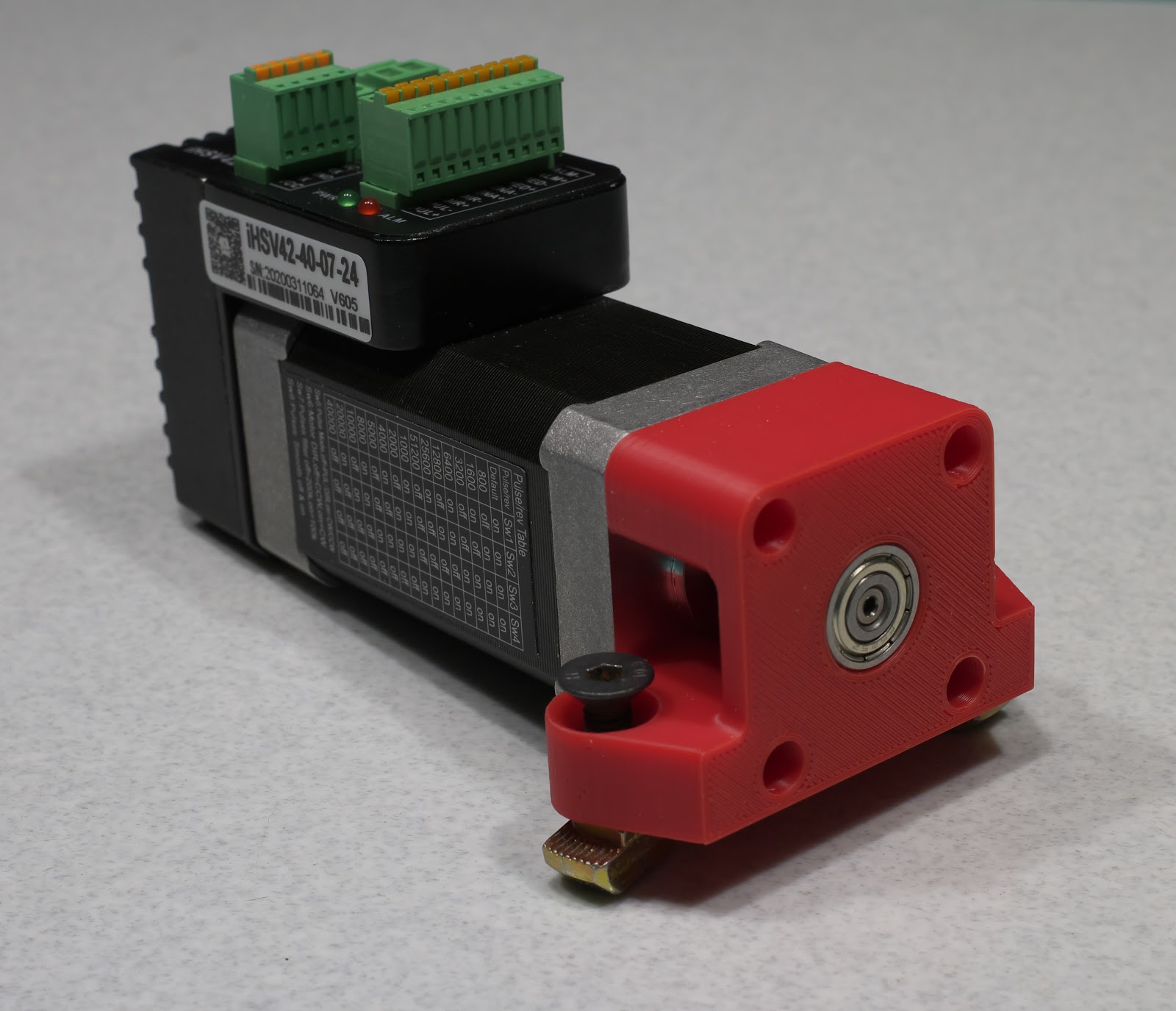 ]
]The only support material was under a 10mm tang to fit into t-slot on the bottom of the print in the picture.
The forces on the bearings are usually radial, and if you print the bearing mount in the XY plane you get maximum strength from the print. If you print with the bearing mount(s) in the XZ or YZ plane, you usually get a much weaker print.
I see you received your JMC servos!
Have you tuned them yet? -
@mrehorstdmd said in Vertical Hole Compression: Possible Solution:
...typically split it into multiple pieces so that all of them get the better alignment assured by printing in the XY plane. It's not cheating to make printed things out of multiple parts!
If you print with the bearing mount(s) in the XZ or YZ plane, you usually get a much weaker print.
I already have my gearbox design spit in to two halves, I wish I could split it in to more pieces but assembly would be a nightmare!
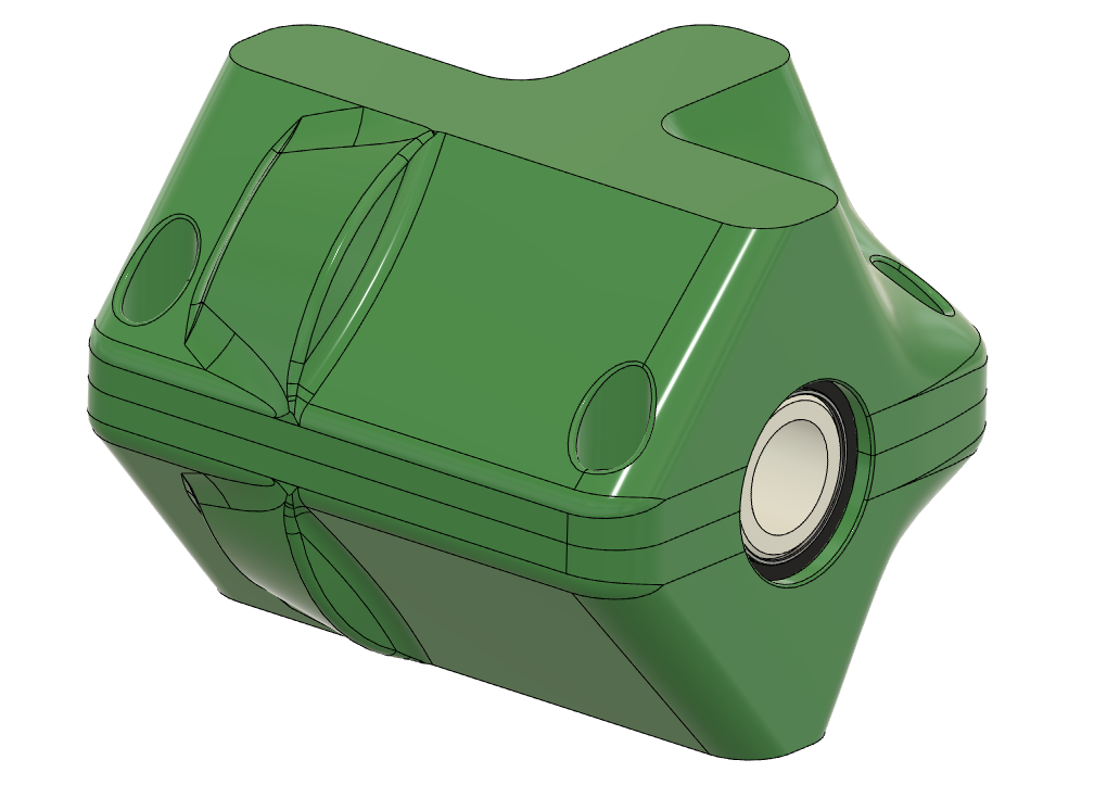
For a frame of reference, those bearings are 15x24x5mm. I'm trying to keep everything as compact as possible.
I do agree that generally the mounts will be weaker in the XZ or YZ plane, but since I will be applying a clamping force to the bearings the printed parts will be under a compressive, not tensile force. From personal experience and reading/watching others' work, printed parts are a far stronger under compressive loads than tensile in the Z axis (as I am sure you already know).
-
@Red-Sand-Robot What layer heights are you printing at?
I've also found that using a piece of breakaway supports can also help. Either in the slicer or even in CAD by simply adding a little block under the top arch of the hole with a small single layer height gap.
-
@Phaedrux I've ranged from 0.2 to 0.28, both as static values and using adaptive layer heights (PrusaSlicer 2.2).
The issue isn't the top of the circle, but the bottom half. I'm only printing the lower half of the circle due to the geometry of my design (less supports) and to avoid the sagging/loss of roundness that occurs on the upper half of circles in Z. Circles in the Z axis will most likely continue be an issue with FFF due to the 2D layers only approximating the curve of a circle, at least until slicers support .step import so smarter compensation can be done on the slicer side of things.
-
I printed a similar gearbox by splitting it into two pieces and printing both with the worm gear bearing slots facing up. Everything fit together quite well. In your gearbox, there would be only one bearing slot for the worm.
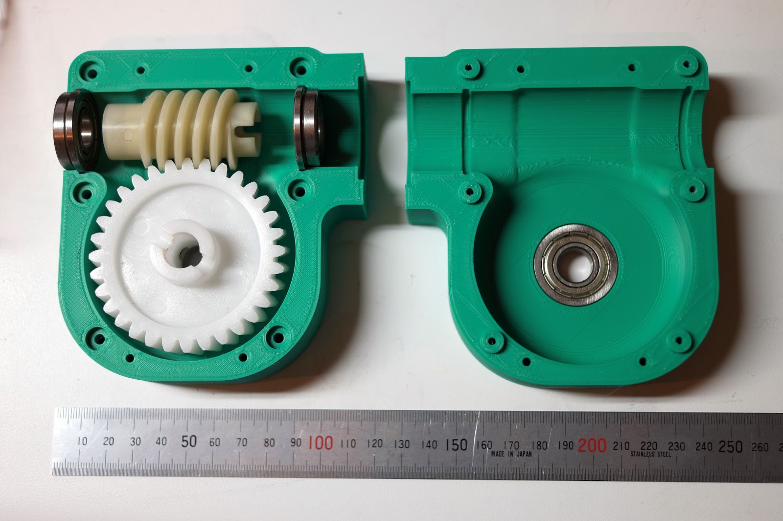
Don't make bosses the way I did! They should be opposite the way I did them- the screws should pass freely through the boss and thread into the body of the other half of the shell.
-
@mrehorstdmd said in Vertical Hole Compression: Possible Solution:
I printed a similar gearbox by splitting it into two pieces and printing both with the worm gear bearing slots facing up. Everything fit together quite well. In your gearbox, there would be only one bearing slot for the worm.
What layer height did you use for that, and did you include any offsets to account for tolerances of your printer? I have seen your printers, and know they are rock solid - but machines extruding melted plastic have their limits.
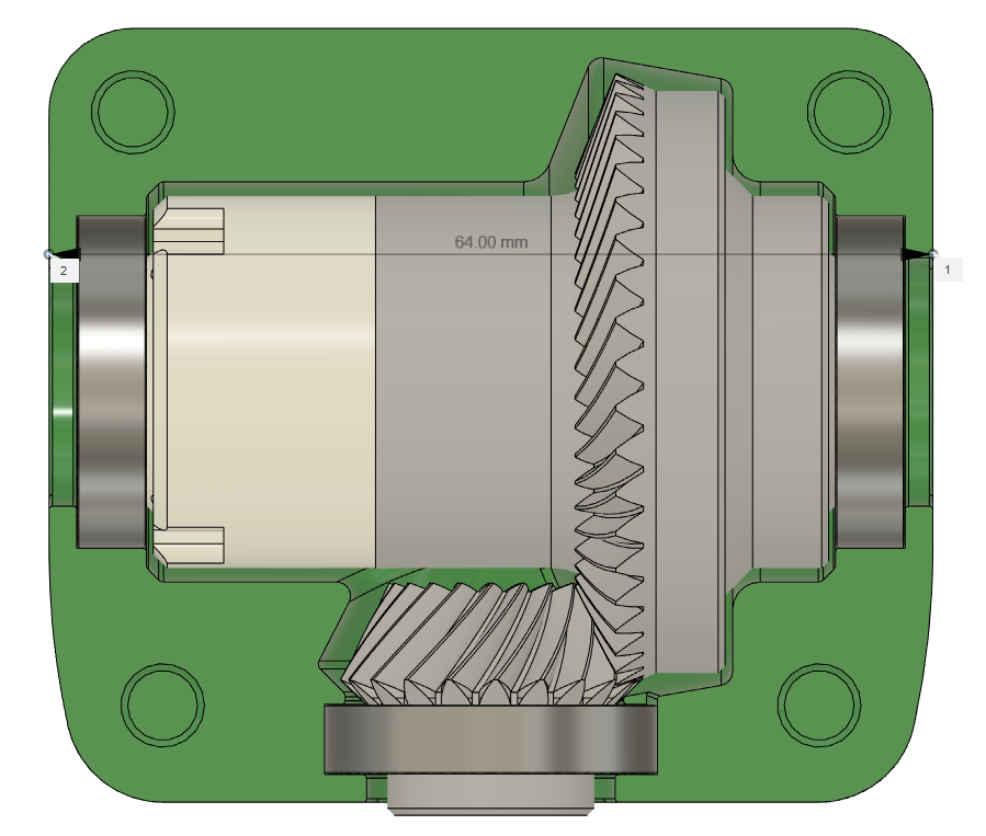
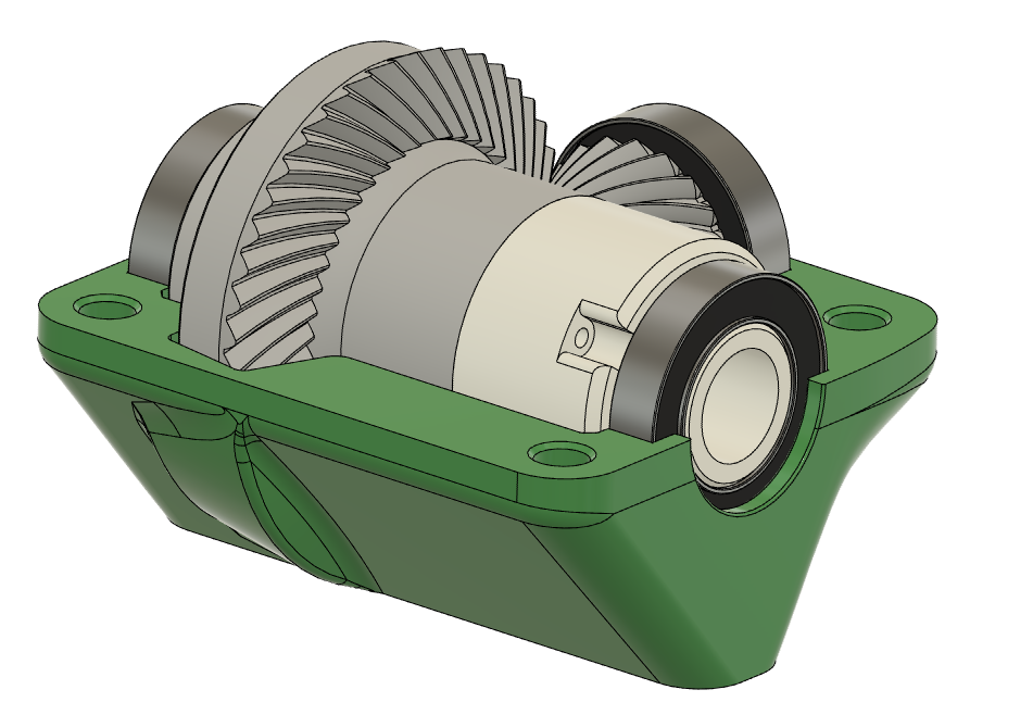
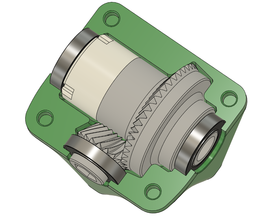
I am printing all three bearing slots facing up, as you did with the work gear bearing slots. Unfortunately for my micro differential, the shape of the bevel gear pairing makes it difficult to successfully split in a different configuration, unless I split it in to four pieces (two for the differential and two to constrain the pinion bearing, to prevent it from shifting forward) - but then alignment issues between the teeth of the pinion and wheel gear could occur.
-
@Red-Sand-Robot I probably used 200 um layers, as I do for most prints. I generally bump round, XY plane hole diameters up by 0.25 mm and find that results in a tight fit- the bearings for the disc gear had to be gently convinced to go into their holes. I use a little less bump in size for the vertical holes- maybe 0.15 mm. I also use random seam position so the little perimeter start/stop bumps will get scattered around and won't mess up the alignment.
-
@mrehorstdmd said in Vertical Hole Compression: Possible Solution:
I also use random seam position so the little perimeter start/stop bumps will get scattered around and won't mess up the alignment.
I dare ask, have you tuned pressure advance?
-
@Phaedrux Probably not as much as I need to...
-
i asked similar question here and got number of valuable answers and tested all of them.
In general the approach was to modify TOP of the circle.
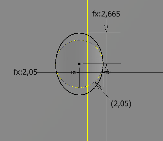
In my case that was not sufficient. So, i made ellipse. in vertical diameter it is 1.3x in horizontal is it the same as hole .
Also i have reduced the hole size. As an example - M5 bolt: hole size 4,1mm (R2.05), ellipse: vertical 2.05*1.3=2.665 horizontal 2.05That gives more or less circle hole on the top and on the bottom as well. illustration is below
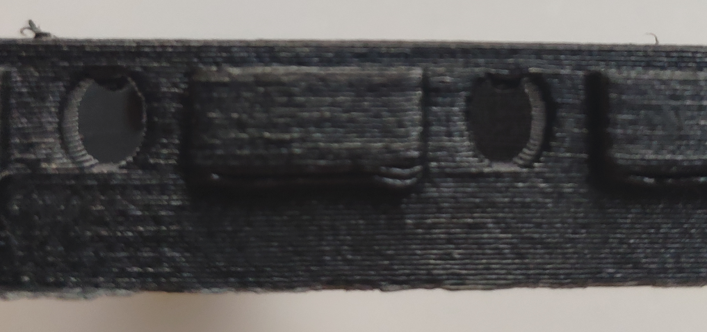
this is what i get without support or cooling with 0.3 layer
and with bolt inside:
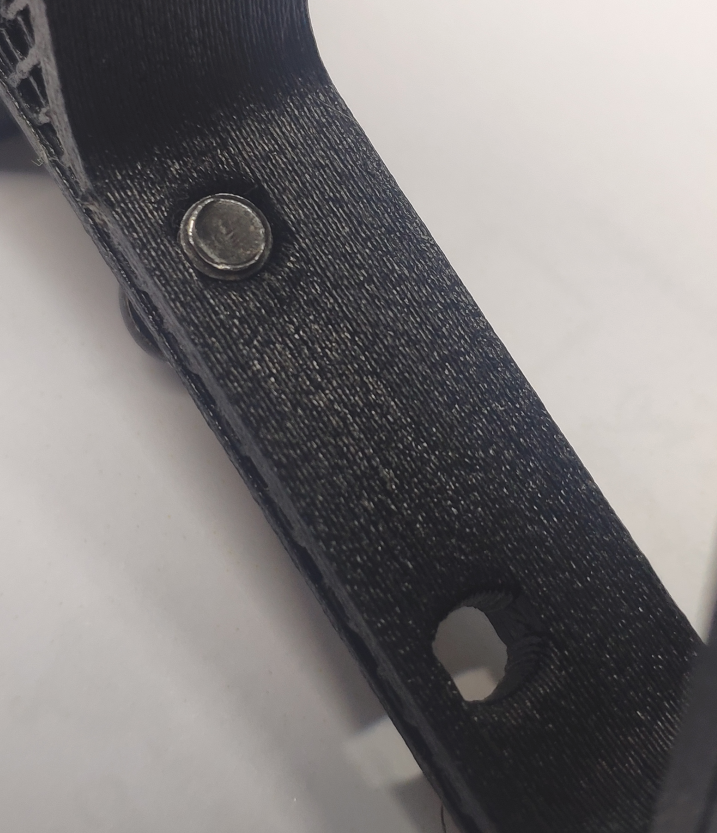
as you can see - bolt sits very well. no spaces either side (if i use "standard" M5 hole, there will be quiet a space on left and right")
M5 goes in like in the nut, but if you want just to insert the bolt, than drill 4.8 mm hole.
You can tell that "drilling is possible without additional ellipse", but from my tests i can say that drilling "standard" hole has high chance of center being offset.hope it helps someone.
-
What about using support in holes?
-
@NitroFreak from my experience in small holes supports may help to avoid small bubble on the top, but they may create bubble on the bottom
and support does not help with holes being not-round...
so i decided not to use supports for this model.