PS_ON not working?
-
i have now added the M80/81 commands at the beginning of the config.g and again no change
M80 ; Turns on the ATX power supply
M81 ; Turns off the ATX power supply -
i have also measured with my meter, that i currently have 3.3v on the PSON connector that is feeding onto the DUET. i assumed that the duet would just ground that pin. but irregardless of m command it still retains the 3.3v.
i also found a note in the forum from one of the duet employees that the GND isnt required so i have since removed it.
-
here is a copy of my config.g
; Configuration file for Duet WiFi (firmware version 2.03)
; executed by the firmware on start-up
;
; generated by RepRapFirmware Configuration Tool v2.1.8 on Thu May 07 2020 17:04:03 GMT-0600 (Mountain Daylight Time); General preferences
M80 ; Turns on the ATX power supply
M81 ; Turns off the ATX power supply
G90 ; send absolute coordinates...
M83 ; ...but relative extruder moves
M550 P"JoehBo3D" ; set printer name; Network
M552 S1 ; enable network
M586 P0 S1 ; enable HTTP
M586 P1 S0 ; disable FTP
M586 P2 S0 ; disable Telnet; Drives
M569 P0 S1 ; physical drive 0 goes forwards
M569 P1 S1 ; physical drive 1 goes forwards
M569 P2 S1 ; physical drive 2 goes forwards
M569 P3 S1 ; physical drive 3 goes forwards
M584 X0 Y1 Z2 E3 ; set drive mapping
M350 X16 Y16 Z16 E16 I1 ; configure microstepping with interpolation
M92 X80.00 Y80.00 Z4000.00 E420.00 ; set steps per mm
M566 X1020.00 Y1020.00 Z24.00 E300.00 ; set maximum instantaneous speed changes (mm/min)
M203 X6000.00 Y6000.00 Z180.00 E1200.00 ; set maximum speeds (mm/min)
M201 X9000.00 Y9000.00 Z100.00 E10000.00 ; set accelerations (mm/s^2)
M906 X800 Y800 Z800 E800 I30 ; set motor currents (mA) and motor idle factor in per cent
M84 S30 ; Set idle timeout; Axis Limits
M208 X0 Y0 Z0 S1 ; set axis minima
M208 X228 Y254 Z203 S0 ; set axis maxima; Endstops
M574 X1 Y1 S1 ; set active high endstops
M574 Z1 S2 ; set endstops controlled by probe; Z-Probe
M558 P1 H5 F-120 T6000 ; set Z probe type to unmodulated and the dive height + speeds
G31 P500 X-24 Y0 Z2.5 ; set Z probe trigger value, offset and trigger height
M557 X15:215 Y15:195 S20 ; define mesh grid; Heaters
M307 H0 B0 S1.00 ; disable bang-bang mode for the bed heater and set PWM limit
M305 P0 T100000 B4138 R4700 ; set thermistor + ADC parameters for heater 0
M143 H0 S120 ; set temperature limit for heater 0 to 120C
M305 P1 T100000 B4138 R4700 ; set thermistor + ADC parameters for heater 1
M143 H1 S280 ; set temperature limit for heater 1 to 280C; Fans
M106 P0 S0 I0 F500 H1 T45 ; set fan 0 value, PWM signal inversion and frequency. Thermostatic control is turned on
M106 P1 S1 I0 F500 H1:1 T45 ; set fan 1 value, PWM signal inversion and frequency. Thermostatic control is turned on; Tools
M563 P0 D0 H1 F0 ; define tool 0
G10 P0 X0 Y0 Z0 ; set tool 0 axis offsets
G10 P0 R0 S0 ; set initial tool 0 active and standby temperatures to 0C; Custom settings
-
@joehsmash according to your config.g your supply turns on then the next line it turns off
-
@LeckieTech good catch, it still doesnt activate the psu tho

-
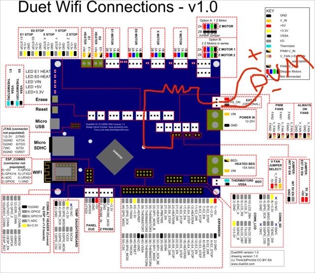
@joehsmash With that output, you can't really read it with a voltmeter unless you add a pull-up resistor. You could use any resistor you have between 1k-100k ohms and pull up to 5 volts.
Send M81 - you should read 5 volts on the middle pin.
Send M80 - you should read 0 volts on the middle pin.
(sorry for the horrible drawing)

-
@joehsmash I suspect that the output is working but isn't one of 2 things.
- on the same ground plane as the PSU
- not providing a strong enough ground to the PSU
-
I didnt test the board, i tested the voltage of the pson of the psu to which i have 3.3v
-
@LeckieTech i had a ground hooked up to the gnd pin on that header and it still didnt work. So i doubt that its a grounding issue. At least initially.
-
@LeckieTech so if i understand you correctly, you want me to pull 5v from the fan header and send it over to the pson pin through a resistor than from the pson to the meter and back to ground?
-
Did anybody find a solution ?
I got the same Problem!! -
@jjuuzzii , I wired up my soft power control a little different.
https://www.randoprojects.com/2020/07/30/duet-2-soft-power-control/
What kind of PSU are you using?