The idea
Measure the force required for extrusion during transient.
The approach is not new, we tackle the task similar to
- Duet forum thread
- Renkforce rf2000 uses a similar system
How we do it - mechanics
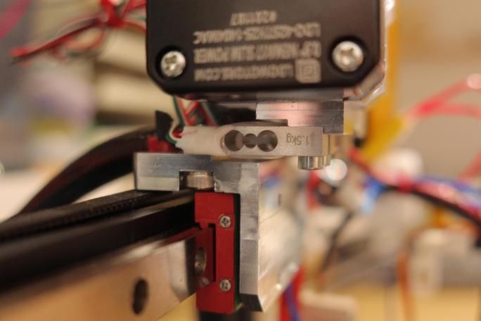
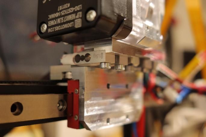
- Separate extruder from cold/hot end with load cells TAL220G
- A first fixture is used to screw the extruder on top of the load cells. The extruder has a M7 thread wich is used with an aluminium tube to fix it to the fixture and with a short PTFE tube inside to guide the filament to the coldend.
- A second fixture is an angled bracket used to screw the load cells on the MGN12H carriage.
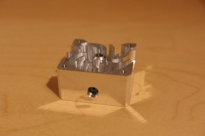
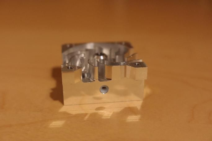
- A third fixture represents the cold end and aligns with the filament path from the extruder. The 4mm hole at the top is used to provide for another short PTFE tube that guides the filament to the heatbreak. A M7 thread at the bottom allows to attach a E3D V6 hotend.
All three mentioned fixtures were manufactured by 3CTS and it became possible for me to realize this idea at all. Thanks guys!
How we do it - electronics + software
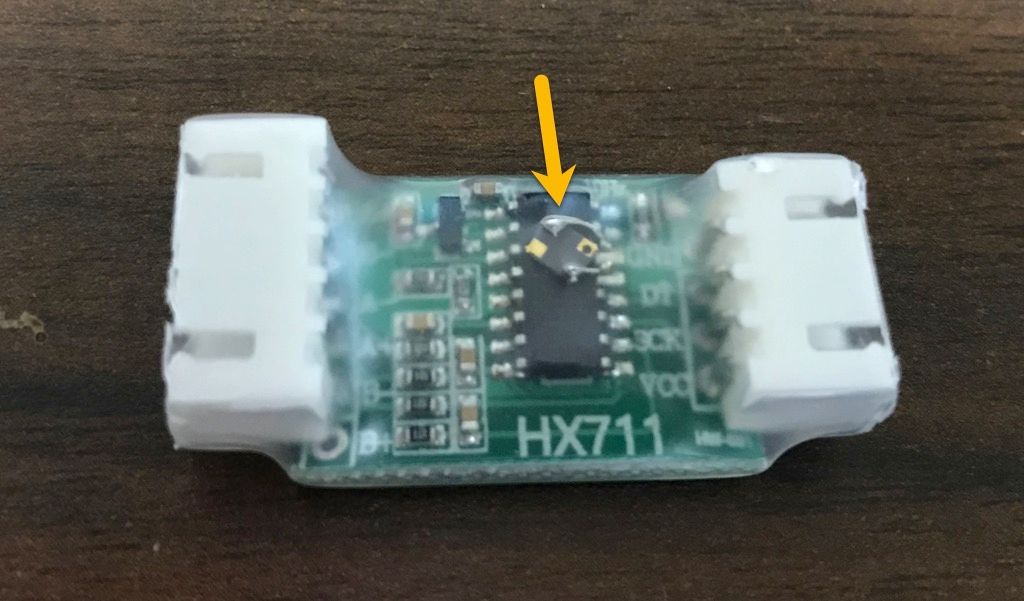
- One of the load cells is attached to a HX711, which in turn is connected to a raspberry pi zero w. There is four load cells, as I was not sure for how much force I needed to prepare for and the 1.5kg sensors were cheap and readily available (the 3kg option was not in stock at the time, so I went for it this way). I guess it could make sense to remove two of the four sensors and improve the sensitivity - but I find the result satisfying already.
- Software readout is done according to Github link
- The HX711 is supplied with 5V from the Pi and takes 80 samples per second, which seems to be sufficient for useful readings, but does not give insight if you want to see what is happening during a retract (which takes only ~10ms in my setup).
- Display the readings at a webpage and embed it within the Duet Web Control.
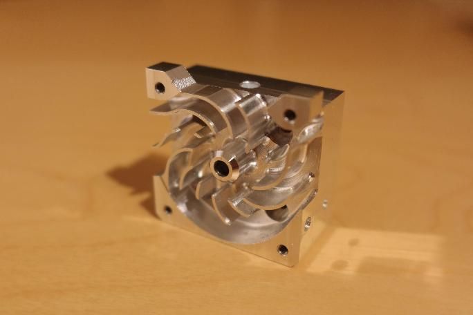
Gallery - first and second fixture
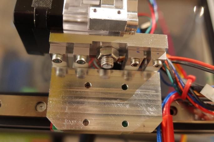
Gallery - third fixture/coldend
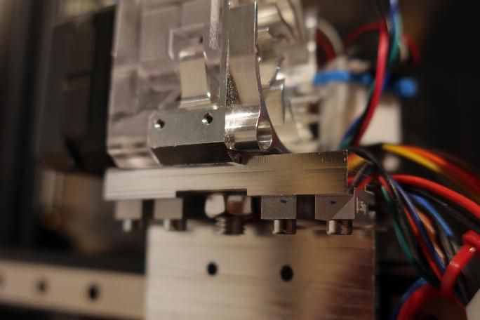
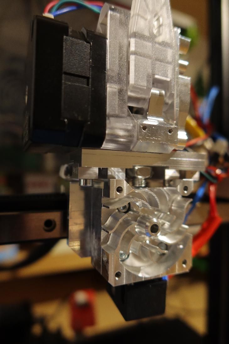
Gallery - full assembly
Exemplary reading
Here you can take a look at the readings from an exemplary print with three retractions taking place. unit=grams
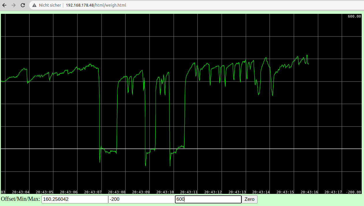
Well, I am still playing with it trying to find out what information can be gained from this system. For now, it helped me dial in retraction and pressure advance, but in the end it does not waive calibration prints. Any suggestions welcome!
")