Duet 3 Z Stepper Noise
-
I Have a CoreXY with 3 Independent Z axis.

I Just swapped from a Duet 2 Wifi to a Duet 3. I have a lot of noise coming from the bed when I move Z up and down. Travel speed isn't that high, the GUI says 17mm/s.
24V 360w PSU
I'm using 17HS19-2004S1 steppers for my Z
I'm using 17HS16-2004S1 steppers for X and Y.I do not have the noise on my X and Y.
Here's my config
; General preferences
M80													; Turns on the ATX power supply
G90                                                ; send absolute coordinates...
M83                                                ; ...but relative extruder moves
;G21													; Set units to Millimeters
M584 E0.0 X0.1 Y0.2 Z0.3:0.4:0.5					; Set drive mapping Z3=Left Front, Z4= Right Rear, Z5=Right Front
M669 K1                                            ; select CoreXY mode

;Network
;M550 P"Red Devil"                                   ; Set machine name
M552 S1                                            ; Enable network
;M587 S"Cowabunga_5G" P"Sexywife16"	           ; Configure access point. You can delete this line once connected
M552 P192.168.1.107					;
M553 P255.255.255.0					;
M554 P192.168.1.1					;
M586 P0 S1                                         ; Enable HTTP
M586 P1 S0                                         ; Disable FTP
M586 P2 S0                                         ; Disable Telnet

; Drives
M569 P0.0 S1                                       ; physical drive 0.0 goes backwards
M569 P0.1 S0                                       ; physical drive 0.1 goes backwards
M569 P0.2 S0                                       ; physical drive 0.2 goes backwards
M569 P0.3 S0                                       ; physical drive 0.3 goes backwards
M569 P0.4 S0                                       ; physical drive 0.4 goes backwards
M569 P0.5 S0                                       ; physical drive 0.5 goes backwards

M671 X-65:363:363 Y166:304:25 S10	   ; leadscrews at Front left, right Front and right rear

M584 X0.1 Y0.2 Z0.3:0.4:0.5 E0.0                           ; set drive mapping Z3=Left Front, Z4= Right Rear, Z5=Right Front
M350 X32 Y32 Z16 E16 I1                            ; configure microstepping with interpolation
M92 X200.00 Y200.00 Z400.00 E410.63                ; set steps per mm
M566 X700.00 Y700.00 Z24.00 E400.00                ; set maximum instantaneous speed changes (mm/min)
M203 X18000 Y18000 Z1000 E20000                   ; Set maximum speeds (mm/min) mm per minute/60=mm per second
M201 X3000 Y3000 Z100 E5000			   ; Set accelerations (mm/s^2)
M906 X1600 Y1600 Z1600 E700 I30                   ; Set motor currents (mA) and motor idle factor in per cent
M84 S120                                             ; Disable motor idle current reduction

; Axis Limits
M208 X-26 Y1 Z0 S1                                   ; set axis minima
M208 X320 Y321 Z445 S0                             ; set axis maxima

; Endstops
M574 X2 S1 P"io1.in"                              ; configure active-high endstop for low end on X via pin !io1.in
M574 Y2 S1 P"io2.in"                              ; configure active-high endstop for high end on Y via pin !io2.in
M574 Z1 S2                                         ; configure Z-probe endstop for low end on Z

; Z-Probe
M950 S0 C"io7.out"                                 ; create servo pin 0 for BLTouch
M558 P9 C"^io7.in" H10 F300 T2000                   ; set Z probe type to bltouch and the dive height + speeds
G31 P500 X47 Y0 Z2.290                               ; set Z probe trigger value, offset and trigger height
M557 X30:270 Y30:270 S80                           ; define mesh grid

; Heaters
M308 S0 P"temp0" Y"thermistor" A"Bed Temp" T100000 B4700 C0.0000000706                   ; configure sensor 0 as thermistor on pin temp0
M308 S1 P"temp1" Y"thermistor" A"Extruder Temp" T100000 B4725 C0.0000000706               ; configure sensor 1 as thermistor on pin temp1
M950 H0 C"out1" T0                                 ; create bed heater output on out0 and map it to sensor 0
M950 H1 C"out2" T1                                 ; create nozzle heater output on out1 and map it to sensor 1
M307 H0 A251.6 C1137.3 D11.0 V24.6 B0              ; Set PID for bed heater
M140 H0                                            ; map heated bed to heater 0
M143 H0 S100                                       ; set temperature limit for heater 0 to 100C
M307 H1 A461.5 C202.9 D3.7 V24.6 S1.0 B0           ; Set PID for Hotend .4Bmm nozzle
M143 H1 S260                         ; Set temperature limit for heater 1 to 260C
M308 S2 P"mcu-temp" Y"mcu-temp" A"Duet Board" ; Configure MCU sensor

; Fans
M950 F0 C"out9" Q500                               ; create fan 0 on pin out9 and set its frequency
M106 P0 C"Layer Fan" S0 H-1                                     ; set fan 0 value. Thermostatic control is turned off
M950 F2 C"out7" Q500                               ; create fan 1 on pin out7 and set its frequency
M106 P2 C"MB Fan" T30:55 H2                                  ; set fan 1 value. Thermostatic control is turned on
M950 F1 C"out8" Q500                               ; create fan 1 on pin out8 and set its frequency
M106 P1 S255 H1 T30                                  ; set fan 1 value. Thermostatic control is turned on
;106 P2 T45:65 H100:101:102
;The fourth example sets up an electronics cooling fan that starts to turn on when the MCU temperature (virtual heater 100) reaches 45C and reaches full speed when the ;MCU temperature reaches 65C or if any TMC2660 drivers (virtual heaters 101 and 102) report that they are over-temperature

; Tools
M563 P0 D0 H1 F0                                   ; define tool 0
G10 P0 X0 Y0 Z0                                    ; set tool 0 axis offsets
G10 P0 R0 S0                                       ; set initial tool 0 active and standby temperatures to 0C

; Custom settings are not defined
M564 H0                                   	   ; Let the Jog buttons work blv: added to allow jog buttons

; Miscellaneous
M575 P1 S1 B57600                                  ; enable support for PanelDue
M911 S10 R11 P"M913 X0 Y0 G91 M83 G1 Z3 E-5 F1000" ; set voltage thresholds and actions to run on power loss
M915
m915
Driver 0.0: stall threshold 1, filter off, steps/sec 200 (7.8 mm/sec), coolstep 0, action: none
Driver 0.1: stall threshold 1, filter off, steps/sec 200 (32.0 mm/sec), coolstep 0, action: none
Driver 0.2: stall threshold 1, filter off, steps/sec 200 (32.0 mm/sec), coolstep 0, action: none
Driver 0.3: stall threshold 1, filter off, steps/sec 200 (8.0 mm/sec), coolstep 0, action: none
Driver 0.4: stall threshold 1, filter off, steps/sec 200 (8.0 mm/sec), coolstep 0, action: none
Driver 0.5: stall threshold 1, filter off, steps/sec 200 (8.0 mm/sec), coolstep 0, action: none
M569 P0
m569 p0
Drive 0 runs forwards, active low enable, step timing fast, mode spreadCycle, ccr 0x08053, toff 3, tblank 1, hstart/hend/hdec 5/0/0, pos 8, tpwmthrs 2000 (0.9 mm/sec), thigh 200 (9.1 mm/sec)
M350
m350
Microstepping - X:32(on), Y:32(on), Z:16(on), E:16(on
First thought it's a setting related to the TMC5560 drivers. When I used the Duet Wifi 2 the noise was non-existent.
-
This post is deleted! -
Bumping post
-
I don't know if the duet3 is the same as the duet 2 for this but on the duet 2 the only way you get the microstepping interpolation is with all the microstepping set at 16x.
-
Hi, which steppers are you using?
I discovered a difference for steppers with more than 4 wires. on these kind of steppers you have the ability to choose parallel or serial wiring. on my side serial was much more noisy than parallel.
i also use a duet3. -
@JamesM correct, the duet 2 wifi and ethernet only work with 16. The maestro works with all. However I couldn't find anything for duet 3
-
@Nathan Nope mine are just 4 wire steppers.
-
@dhusolo according to
https://duet3d.dozuki.com/Wiki/Choosing_and_connecting_stepper_motors
"The drivers on Duet 2 Maestro and Duet 3 can interpolate at any microstepping setting"
Duet3 can handle all microstepping. -
Common causes if stepper motor noise:
- Mid-band resonance. This is a speed-sensitive property of the stepper motors.
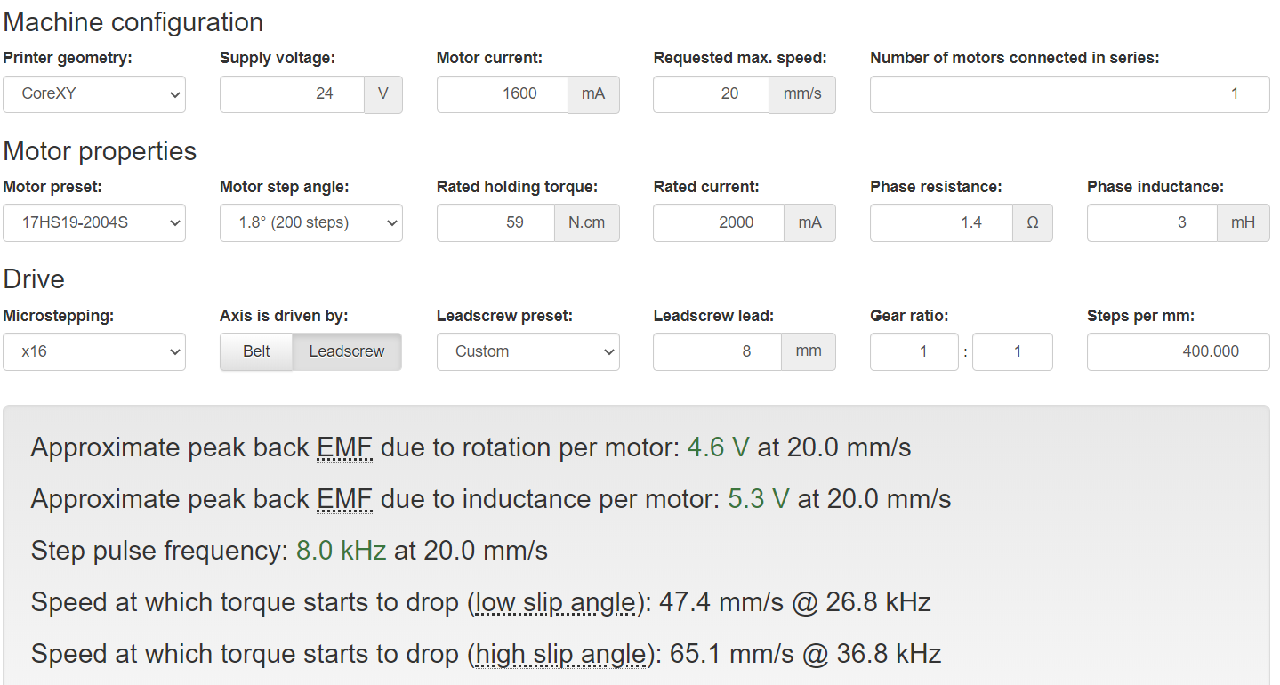
- Running the stepper motors too fast for the VIN voltage you are using. Try moving Z at different speeds, to see if there is a speed at which the noise gets bad. Use the motor EMF calculator at reprapfirmware.org to approximate the maximum speed you can get before torque reduces. The motors will get noisier at/above about the same speed.
I can't think of a reason why a Duet 3 would give more noise than a Duet 2 with the same settings, although Trinamic may have made some subtle change to the chopper timing in the stepper drivers.
Duet WiFi hardware designer and firmware engineer
Please do not ask me for Duet support via PM or email, use the forum
http://www.escher3d.com, https://miscsolutions.wordpress.com -
@dc42 It does get quieter if I slow the speed down.
G1 Z10 F1000 is pretty loud.
G1 Z50 F850 the noise is eliminated.Can you confirm my movement settings is correct in my config in my first post? When I changed to Duet 3 from Duet 2 Wifi I kept the same
M350 X32 Y32 Z16 E16 I1
M92 X200.00 Y200.00 Z400.00 E410.63
M566 X700.00 Y700.00 Z24.00 E400.00
M203 X18000 Y18000 Z1000 E20000
M201 X3000 Y3000 Z100 E5000
M906 X1600 Y1600 Z1600 E700 I30
I tried using the EMF calculator, not sure I got everything right.
-
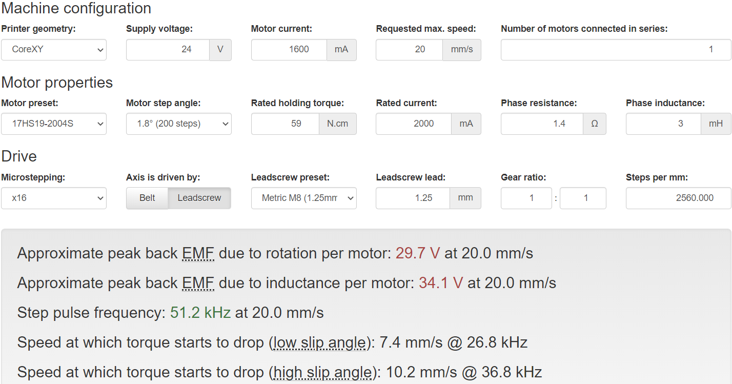
The leadscrew parameters that you set in the calculator give 2560 steps/mm @ x16 microstepping, however in your M92 command you specify 400. So something isn't right.
-
@dhusolo You'll need to specify the correct Leadscrew lead, you're probably not using M8 lead screws.
-
@Phaedrux 2mm pitch 4 starts yup thanks. I realized what I did wrong.