• Tags
  • Documentation
  • Order
  • Register
  • Login
Duet3D Logo Duet3D
  • Tags
  • Documentation
  • Order
  • Register
  • Login

Endstop LED lighting, but DWC does not show them triggered

Scheduled Pinned Locked Moved
Duet Hardware and wiring
4
33
1.3k
Loading More Posts
  • Oldest to Newest
  • Newest to Oldest
  • Most Votes
Reply
  • Reply as topic
Log in to reply
This topic has been deleted. Only users with topic management privileges can see it.
  • undefined
    fcwilt @Leav
    last edited by 23 Jul 2020, 04:20

    @Leav

    Well if the output of the device only goes to 0.7 volts when you add in the voltage drop across the diode you added you are up to about 1.4 volts.

    You measured 1.2 volts - so that is about right.

    If 1.2 volts is too high then you may have to use the multiple diode approach I mentioned since this would allow pulling down the input to the 0.7 volts of the device while preventing the device from pulling up the input higher than 4 diode drops - or 2.8 volts. Three diodes might be enough if 2.1 volts is sufficient to deactivate the input.

    Frederick

    Printers: a small Utilmaker style, a small CoreXY and a E3D MS/TC setup. Various hotends. Using Duet 3 hardware running 3.4.6

    1 Reply Last reply Reply Quote 0
    • ?
      A Former User @Leav
      last edited by 23 Jul 2020, 06:56

      @Leav said in Endstop LED lighting, but DWC does not show them triggered:

      *** Disconnected from the board they pull down the voltage to 0.7v!** holy moly this is the problem!

      i doubt it, 0.7v across the NPN junction on the sensor is well below the logic threshold MIN [0.8V, 0.3 × VDDIO] for the input pin; but it does mean that adding a diode (another PN junction) adds another 0.7v which brings you over the threshold. Maybe a schotty diode would do the trick, but not alot of margins.

      unfortunately quick google search doesn't yield a datasheet that shows a pull up resistor in the sensor so you'd probably have to measure the value of the pull up and design your voltage divider accordingly.

      1 Reply Last reply Reply Quote 0
      • undefined
        Leav
        last edited by 23 Jul 2020, 20:14

        @bearer @fcwilt

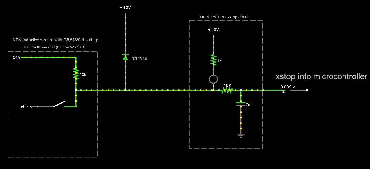
        What do you think of this setup? (proposed on reddit).

        Is there any chance of damaging the 3.3v rail with a setup like this?

        685d0aeb-8406-4a92-bccc-162aa9510324-image.png
        410e8a6f-a458-43ae-8285-b6c78f6d8711-image.png

        1 Reply Last reply Reply Quote 0
        • undefined
          fcwilt
          last edited by 23 Jul 2020, 20:39

          Hi,

          Well I would not try that approach without hearing from dc42 first.

          Perhaps the multiple diode approach seems a bit of a kludge but it is safe.

          Do you know what the logic threshold voltages are for this Duet input. Normally a logic 0 would be specified as being below some fixed voltage and a logic 1 would be defined as being above some fixed voltage.

          With a supply voltage of 3.3 it is possible that 2.1 (three diodes) would qualify as a logic 1.

          So we are only talking about two additional diodes.

          There is a type of diode called a zener which comes in different voltage ratings which could be used in your case to insure the input doesn't exceed a certain value.

          I saw an assortment on Amazon that had numerous low voltage devices:

          Chanzon 34 Values 0.5W Zener Diode Assorted Kit (2V 2.2V 2.4V 2.7V 3V 3.3V...) plus other much higher values. It was $7 for 34 diodes.

          If you didn't mind using an LED they have different forward voltage drops depending on color. I believe I have a batch of white ones rated at 3 volts.

          Frederick

          Printers: a small Utilmaker style, a small CoreXY and a E3D MS/TC setup. Various hotends. Using Duet 3 hardware running 3.4.6

          ? 1 Reply Last reply 23 Jul 2020, 20:55 Reply Quote 0
          • ?
            A Former User @fcwilt
            last edited by A Former User 23 Jul 2020, 20:55

            @fcwilt said in Endstop LED lighting, but DWC does not show them triggered:

            Do you know what the logic threshold voltages are for this Duet input.

            @bearer said in Endstop LED lighting, but DWC does not show them triggered:

            the logic threshold MIN [0.8V, 0.3 × VDDIO] for the input pin

            (high side is MIN [2.0V, 0.7 × VDDIO])

            undefined 1 Reply Last reply 23 Jul 2020, 21:02 Reply Quote 0
            • undefined
              fcwilt @A Former User
              last edited by 23 Jul 2020, 21:02

              @bearer said in Endstop LED lighting, but DWC does not show them triggered:

              the logic threshold MIN [0.8V, 0.3 × VDDIO] for the input pin

              Normally there would be two specs - one for a logic 0 and one for a logic 1.

              Do you have a link to this info?

              Thanks.

              Frederick

              Printers: a small Utilmaker style, a small CoreXY and a E3D MS/TC setup. Various hotends. Using Duet 3 hardware running 3.4.6

              1 Reply Last reply Reply Quote 0
              • ?
                A Former User
                last edited by 23 Jul 2020, 21:05

                page 1355
                http://ww1.microchip.com/downloads/en/devicedoc/atmel-11157-32-bit-cortex-m4-microcontroller-sam4e16-sam4e8_datasheet.pdf

                undefined 1 Reply Last reply 23 Jul 2020, 21:06 Reply Quote 0
                • undefined
                  fcwilt @A Former User
                  last edited by 23 Jul 2020, 21:06

                  @bearer said in Endstop LED lighting, but DWC does not show them triggered:

                  page 1355
                  http://ww1.microchip.com/downloads/en/devicedoc/atmel-11157-32-bit-cortex-m4-microcontroller-sam4e16-sam4e8_datasheet.pdf

                  Thank you.

                  Frederick

                  Printers: a small Utilmaker style, a small CoreXY and a E3D MS/TC setup. Various hotends. Using Duet 3 hardware running 3.4.6

                  1 Reply Last reply Reply Quote 0
                  • undefined
                    Leav
                    last edited by Leav 25 Jul 2020, 08:46

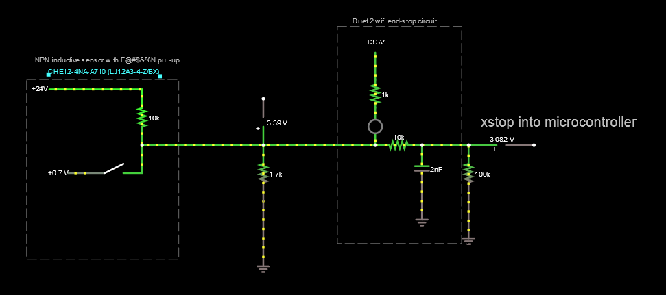
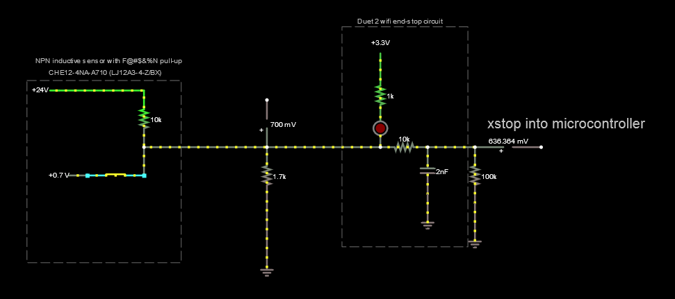
                    Solved it! Thanks everyone for your help and guidance.

                    For posterity, I ended up using a pull down resistor of 1.7K, which balances the effects of:

                    • pull up in sensor
                    • pull up in Duet

                    282187fc-c5f3-49e3-8c35-5c01c0a3fa27-image.png
                    87f8cd7e-5964-4ffc-8da8-06216c1a3bb5-image.png

                    undefined 1 Reply Last reply 25 Jul 2020, 08:51 Reply Quote 0
                    • undefined
                      dc42 administrators @Leav
                      last edited by dc42 25 Jul 2020, 08:51

                      @Leav said in Endstop LED lighting, but DWC does not show them triggered:

                      For posterity, I ended up using a pull down resistor of 1.7K

                      That is the standard way to use a PNP-output sensor. It's the same as for a Z probe (see https://duet3d.dozuki.com/Wiki/Connecting_a_Z_probe#Section_PNP_output_normally_open_inductive_or_capacitive_sensor) except that you need a lower value pulldown resistor, because of the pullup resistor in the Duet.

                      The output of an NPN sensor can be connected directly to the endstop input on all modern Duets, and should work that way.

                      Duet WiFi hardware designer and firmware engineer
                      Please do not ask me for Duet support via PM or email, use the forum
                      http://www.escher3d.com, https://miscsolutions.wordpress.com

                      undefined 1 Reply Last reply 25 Jul 2020, 13:35 Reply Quote 0
                      • undefined
                        Leav @dc42
                        last edited by 25 Jul 2020, 13:35

                        @dc42 said in Endstop LED lighting, but DWC does not show them triggered:

                        The output of an NPN sensor can be connected directly to the endstop input on all modern Duets, and should work that way.

                        If I understand correctly, I think I have a very weird "NPN-ish" sensor, since it has a pull-up internally. connecting it directly would connect 24v to the 3.3v rail, which I understand is not a good thing, even with all the resistors in the way.

                        1 Reply Last reply Reply Quote 0
                        32 out of 33
                        • First post
                          32/33
                          Last post
                        Unless otherwise noted, all forum content is licensed under CC-BY-SA