How to setup the Bigtreetech smart filament sensor?
-
@arhi said in How to setup the Bigtreetech smart filament sensor?:
What did you power it with? 5V? 12V?
Only 3V3 and 5V never any higher.
Since I have to wait anyway for a replacement chip could I measure on the pins for resistance to check? Otherwise I'll just going to solder it back and hope it magically fixed itself.
-
@Infinitysnek said in How to setup the Bigtreetech smart filament sensor?:
@arhi said in How to setup the Bigtreetech smart filament sensor?:
What did you power it with? 5V? 12V?
Only 3V3 and 5V never any higher.
omni did the same and did not kill it
Since I have to wait anyway for a replacement chip could I measure on the pins for resistance to check?
Nope, you need to power it on to test it.
Otherwise I'll just going to solder it back and hope it magically fixed itself.
it is easiest way to test it, you can easily remove it if it does not work.
When you power it (3.3V enough) irrelevant to what input is, output (pins 4 and 6) must be either ground or vcc, can't be nothing in between, if you measure something in between it is dead. BUT make sure you keep the sensor in dark when you are measuring as if the sensor is picking up some noise it could be turning the input on/off quickly that will then translate to output going quickly between Vcc and Vss and since you are measuring with DMM and not a scope you will get some RMS value that will be between Vcc and Vss. So put some metal cap over the transistor when measuring outputs
-
@arhi said in How to setup the Bigtreetech smart filament sensor?:
@Infinitysnek your schematic was very close to the real thing
 ...
...here's my take
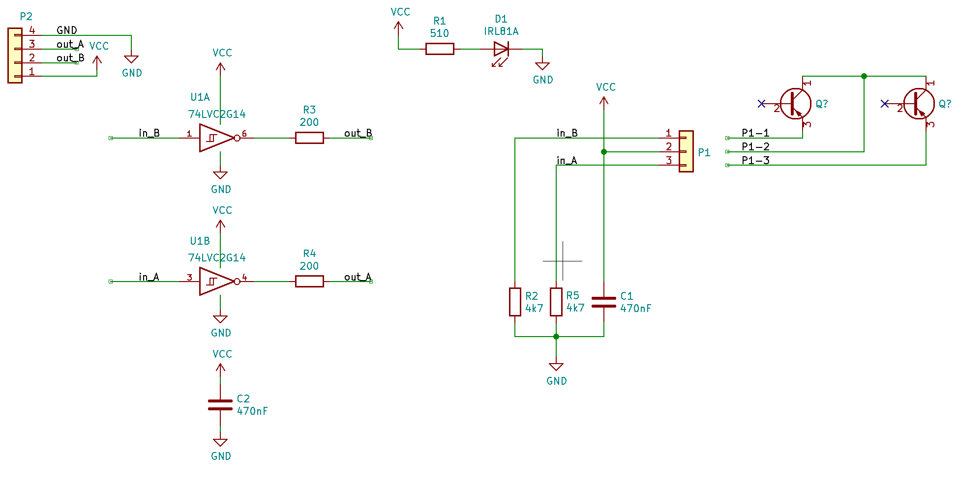
The two phototransistors will be NPN, but otherwise that looks highly plausible. In which case, it has quadrature outputs, so by using two inputs on the Duet and appropriate firmware it would be possible to sense direction of filament travel as well as amount.
Duet WiFi hardware designer and firmware engineer
Please do not ask me for Duet support via PM or email, use the forum
http://www.escher3d.com, https://miscsolutions.wordpress.com -
@dc42 said in How to setup the Bigtreetech smart filament sensor?:
The two phototransistors will be NPN
I never seen PNP photo transistor, but with NPN one would normally do E to Vss, out from C and pull up resistor from C to Vcc, but here the C is on Vcc and output is on the bottom which is why I assumed PNP and not NPN .. in any case works the same as base does not exist
it has quadrature outputs
I assumed that transistors are one next to another so that light opens one first than another, but tbh didn't manage to get that on the scope, they both open/close at the same time
so by using two inputs on the Duet and appropriate firmware it would be possible to sense direction of filament travel as well as amount.
is that needed at all? firmware knows the direction it is turning the motor at ?
I'm using on my printer (not yet enabled still using in disabled state) a 600 steps optical encoder but only the A output.
-
@arhi said in How to setup the Bigtreetech smart filament sensor?:
they both open/close at the same time
would be okay in one direction, did you try both?
-
@bearer said in How to setup the Bigtreetech smart filament sensor?:
@arhi said in How to setup the Bigtreetech smart filament sensor?:
they both open/close at the same time
would be okay in one direction, did you try both?
I did not waste too much time on it as RRF uses only one impulse train anyhow so as soon as I got it working I wrapped it up and moved to a next task
") and whatever's in that IR receiver is not very useful as I can't purchase another one like that so investigation was not going anywhere
and whatever's in that IR receiver is not very useful as I can't purchase another one like that so investigation was not going anywhere But in both direction one need to come first they should never turn on in the same time
-
@arhi said in How to setup the Bigtreetech smart filament sensor?:
But in both direction one need to come first they should never turn on in the same time
not a problem as long as its different in the other direction. (ofc. if they turn on and off at the same time in one direction it'll make it tricky to distinguish the other direction)
-
@arhi said in How to setup the Bigtreetech smart filament sensor?:
and, def. works

need to be now properly configured (this is configured for my encoder) but to get you started
M591 D0 P7 C"e0stop" L0.5 R90:110 E3 S0now you need to setup your own L value and your own span .. for start it's disabled but will collect data, when you are happy with the way you calibrated it you enable it and enjoy
@omni 's U1 was not dead, I'm not sure how was he connecting it when it was not working but he did not burn the U1 so I just retraced the whole schematic (I desoldered the photo transistor pack to test it separately and make sure it's not ghosting my schematic, and then put it back after I was done, tested transistors separately with IR transmitter from a remote controller
)All in all, it works directly from 3v3 so all pins you need are on the E0STOP and E1STOP connectors on duet2ethernet (I assume the other duet's have similar/same connector)
So after a month I have a working sensor. Measured the signal pin and it now gives a 3.3v pulse like it should and wired it all up like you mentioned earlier.
Yet I keep getting no data received. I've switched to the other extruder port to check and changed all the settings multiple times yet nothing seems to be doing anything.... -
@Infinitysnek try a simple test
- remove your "real filament" going trough the sensor and feed it to your extruder directly
- push a 20cm piece of filament into the sensor
- connect the sensor to duet and configure (disabled state)
- start any print from sd
- when the printer start printing check the status of the sensor (should be no data)
M591 D0 - now move, using your hand, those 20 cm of filament all the way trough the sensor one way, then return it all the way to the other end, repeat this few times
- check the status again
M591 D0
you should now see some data
-
@arhi Well at least something changed. I tried that as well as doing a full print. Now it says
no calibration dataso I assume my config isnt right yet? -
Just a short update from my side about the Bigtree filament sensor.... It works as intended now!
My settings are M591 D0 P7 C"e0stop" L7 R75:125 E22 S1
The readings are usually from 93 to 108%, but I keep it on the safe side with the 75/125 % min/max settings.
It already saved one print....
Hope it helps.
-
its SN74LVC1G14 Single Schmitt-Trigger Inverter
you can refere to Page 11 ( https://www.ti.com/lit/ds/symlink/sn74lvc1g14.pdf?ts=1601472384457&ref_url=https%253A%252F%252Fwww.google.com%252F)
i hope this useful
-
I don't know if this will help anyone but I have been been running the BTT filament sensor for a few months ago with the below settings. Besides for a few false faults while printing with some clearish filament it's been working great!
M591 D0 P7 C"e0_stop" S1 R80:120 L6.2 E18.6M591 D0 Pulse-type filament monitor on pin e0stop, enabled, sensitivity 6.200mm/pulse, allowed movement 80% to 120%, check every 18.6mm, measured sensitivity 6.252mm/pulse, measured minimum 96%, maximum 102% over 33984.9mm -
@phiednate how do you connect to duet/duex board? Is the extra circuitry discussed above necessary to get it working?
-
@Popstar
No additional electronics is needed. It works as is - without any problems - just make sure you get the pinout right and put this line to configure the sensor :M591 D0 P7 C"^e0stop" L7 R50:250 E22 S1 ;pulse, disabled, 7 mm/pulse, measure every 22 sec, minimum 50 maximum 250
Also it would be wise to disassemble the sensor and "squeeze" the spring a little bit, to make the filament go through more easily, since by default the spring is too strong and puts a lot of resistance to the filament flow....
-
I just bought this sensor and wanted to add that the new case is injection molded, not 3d printed like the older version.

It still uses the "Roller Encoder v1.2" PCB.

I noticed the idler wheel with "V" groove was not lined up, so I loosened the 3mm screw to give it some movement, so it can match up with filament against the roller encoder wheel. Here is a picture looking through the filament channel, you can see the "V" is now center, where before it was toward to bottom (misaligned).

I'm very interested in looking at the quadrature output, if it exists (maybe in another thread). Also, this platform might provide a way to replace the quadrature wheel with solid plastic part + 1x2mm magnet(s) with analog hall effect sensor + ATTiny45 to make higher precision (definitely other thread).
Thanks for the prior research thus far, this was very helpful to me, and I wanted to contibute some current pictures and my tip about aligning the idler.
-Scott
-
@dc42
I have the Duet 3 6hc in my open build machine, I followed your wiring scheme and used io5.
Here is my config.
firmware version 3)
; executed by the firmware on start-up
;
; generated by RepRapFirmware Configuration Tool v3.2.3 on Mon Mar 08 2021 08:53:31 GMT-0600 (Central Standard Time); General preferences
G90 ; send absolute coordinates...
M83 ; ...but relative extruder moves
M550 P"Colossus Openbuild" ; set printer name; Network
M552 P0.0.0.0 S1 ; enable network and acquire dynamic address via DHCP
M586 P0 S1 ; enable HTTP
M586 P1 S0 ; disable FTP
M586 P2 S0 ; disable Telnet; Drives
M569 P0.3 S1 ; physical drive 0.3 goes forwards
M569 P0.2 S1 ; physical drive 0.2 goes forwards
M569 P0.0 S1 ; physical drive 0.0 goes forwards
M569 P0.4 S1 ; physical drive 0.4 goes forwards
M584 X0.3 Y0.2 Z0.0:0.1 E0.4 ; set drive mapping
M671 X-122.25:689.20 Y0:0 S3.0 ; leadscrews at left (connected to Z0) and right (connected to Z1) of X axis
M350 X32 Y32 Z32 E16 I1 ; configure microstepping with interpolation
M92 X106.5 Y257 Z795.00 E339.00 ; set steps per mm
M566 X900.00 Y900.00 Z60.00 E120.00 ; set maximum instantaneous speed changes (mm/min)
M203 X6000.00 Y6000.00 Z180.00 E1200.00 ; set maximum speeds (mm/min)
M201 X500.00 Y500.00 Z20.00 E250.00 ; set accelerations (mm/s^2)
M906 X900 Y3000 Z3000 E800 I30 ; set motor currents (mA) and motor idle factor in per cent
M84 S30 ; Set idle timeout; Axis Limits
M208 X0 Y0 Z0 S1 ; set axis minima
M208 X609 Y609 Z762 S0 ; set axis maxima; Endstops
M574 X1 S1 P"!^io1.in" ; configure active-high endstop for low end on X via pin !^io1.in
M574 Y1 S1 P"!^io2.in" ; configure active-high endstop for low end on Y via pin !^io2.in
M574 Z1 S2 ; configure Z-probe endstop for low end on Z
M591 D0 P7 C"io5.in" L7 R55:150 E22 S1 ;Bigtree smart filament moniter v2 set to moniter between 55%-150% of 7 counts over a distance of 22mmM591 D0 ; display filament sensor parameters for extruder drive 4
; Z-Probe
M950 S0 C"io7.out" ; create servo pin 0 for BLTouch
M558 P9 C"^io7.in" H5 F120 T6000 ; set Z probe type to bltouch and the dive height + speeds
G31 P100 X60 Y0 Z1.272 ; set Z probe trigger value, offset and trigger height
M557 X100:500 Y100:500 S100 ; define mesh grid; Heaters
M308 S0 P"temp0" Y"thermistor" T100000 B4138 ; configure sensor 0 as thermistor on pin temp0
M950 H0 C"out1" T0 ; create bed heater output on out1 and map it to sensor 0
M307 H0 B1 S10.00 ; enable bang-bang mode for the bed heater and set PWM limit
M140 H0 ; map heated bed to heater 0
M143 H0 S110 ; set temperature limit for heater 0 to 120C
M308 S1 P"temp1" Y"thermistor" T100000 B4138 ; configure sensor 1 as thermistor on pin temp1
M950 H1 C"out2" T1 ; create nozzle heater output on out2 and map it to sensor 1
M307 H1 B0 S1.00 ; disable bang-bang mode for heater and set PWM limit
M143 H1 S280 ; set temperature limit for heater 1 to 280C; Fans
M950 F0 C"out8" Q500 ; create fan 0 on pin out8 and set its frequency
M106 P0 C"Tool Fan" S0 H-1 ; set fan 0 name and value. Thermostatic control is turned off
M950 F1 C"out6" Q500 ; create fan 1 on pin out6 and set its frequency
M950 F2 C"out7" Q500 ; create fan 2 on pin out7 and set its frequency
M106 P1 C"Extruder" S1 H1 T45 ; set fan 1 name and value. Thermostatic control is turned on; Tools
M563 P0 S"Hemera" D0 H1 F0 ; define tool 0
G10 P0 X0 Y0 Z0 ; set tool 0 axis offsets
G10 P0 R0 S0 ; set initial tool 0 active and standby temperatures to 0C; Custom settings are not defined
; Miscellaneous
M575 P1 S1 B57600 ; enable support for PanelDueall I needed to do was wire 3.3vdc to pin 1, io5.in to pin 3 and ground to pin 4 and it works great
-
@phiednate Hi I just got BTT filament sensor. I did read a few treads, but there is no clear post about wiring, could you be so kind to share your wiring diagram
-
@martin7404 look further up the post, pin 1 is 3.3 - 5vdc in. pin 3 is pulse out, pin 2 is not used and pin 4 is ground.
-
 undefined Phaedrux referenced this topic
-
Adding some information about possible problems with this sensor if anyone will dig out this thread (as I did).
In my case sensor had intermittent failure. Once a few or a dozen minutes of printing it reported no filament (== no "low" pulses were sent). Then after 1-2 days it died completely.
It turns out that when I mounted it using one of thingiverse mounts screw pressed a tiny bit on the side of connector causing it to rip ground path directly under connector. That caused no power on C145 chip (well, there was ~1.2V there).
The fault was only visible under microscope and even then it wasn't immediately obvious/visible because main pins were soldered fine. Only one pin on the side (the mounting one) was ripped (and was up over pcb a fraction of mm).
-
 undefined RandyL00123 referenced this topic