6 axis delta 3D printer
-
@dc42, what about a delta with 2 moving plateforms using the same rails for the 2 sets of arms?
The upper plateform/arms would be a classic delta, for XYZ translation, and the lower plateform/arms would be the bed, for A/B rotation (and an additional Z translation, as there is 3 dof), resulting in a 5 axis kinematic.
Is such configuration easier to implement?
What about build errors compensation? Is it something hard to do?Thanks,
Frédéric
-
@dc42 said in 6 axis delta 3D printer:
[...] definitely use a board with built-in floating point hardware [...]
Sorry to derail this thread slightly. This line caught my attention due to the fact that I recently realized that the Duet 3 has hardware floating point to double precision.
What exactly does this mean?

I get what floating point is. I get what double floats are. I get the implications of a dedicated hardware component handling these.
But is this automatic? Does the hardware floating point capability of one Duet board vs another automatically improve performance of dealing with floats? Or, does this functionality need to be manually addressed in the RRF code?
Does the Duet 3 perform better when calculating double precisions floats vs the Duet 2? Does the Duet 2 Maestro suffer performance loss in comparison, when dealing with floating point math? (When using RRF as-is.)
-
@bot said in 6 axis delta 3D printer:
But is this automatic? Does the hardware floating point capability of one Duet board vs another automatically improve performance of dealing with floats? Or, does this functionality need to be manually addressed in the RRF code?
It's automatic, after setting up the compiler settings and startup code to use the built-in floating point hardware (which we do).
Does the Duet 3 perform better when calculating double precisions floats vs the Duet 2?
Yes, however RRF for Duet 2 hardly ever uses double precision floats, because single precision is sufficient.
Does the Duet 2 Maestro suffer performance loss in comparison, when dealing with floating point math? (When using RRF as-is.)
Yes. So the Maestro is less suitable for controlling SCARA and Polar printers in particular.
Duet WiFi hardware designer and firmware engineer
Please do not ask me for Duet support via PM or email, use the forum
http://www.escher3d.com, https://miscsolutions.wordpress.com -
Thank you very much. I'm diving into learning about embedded C programming right now, with no disillusions that I will be making any viable contributions, but just to understand better how things work. Your answer helps a lot!
-
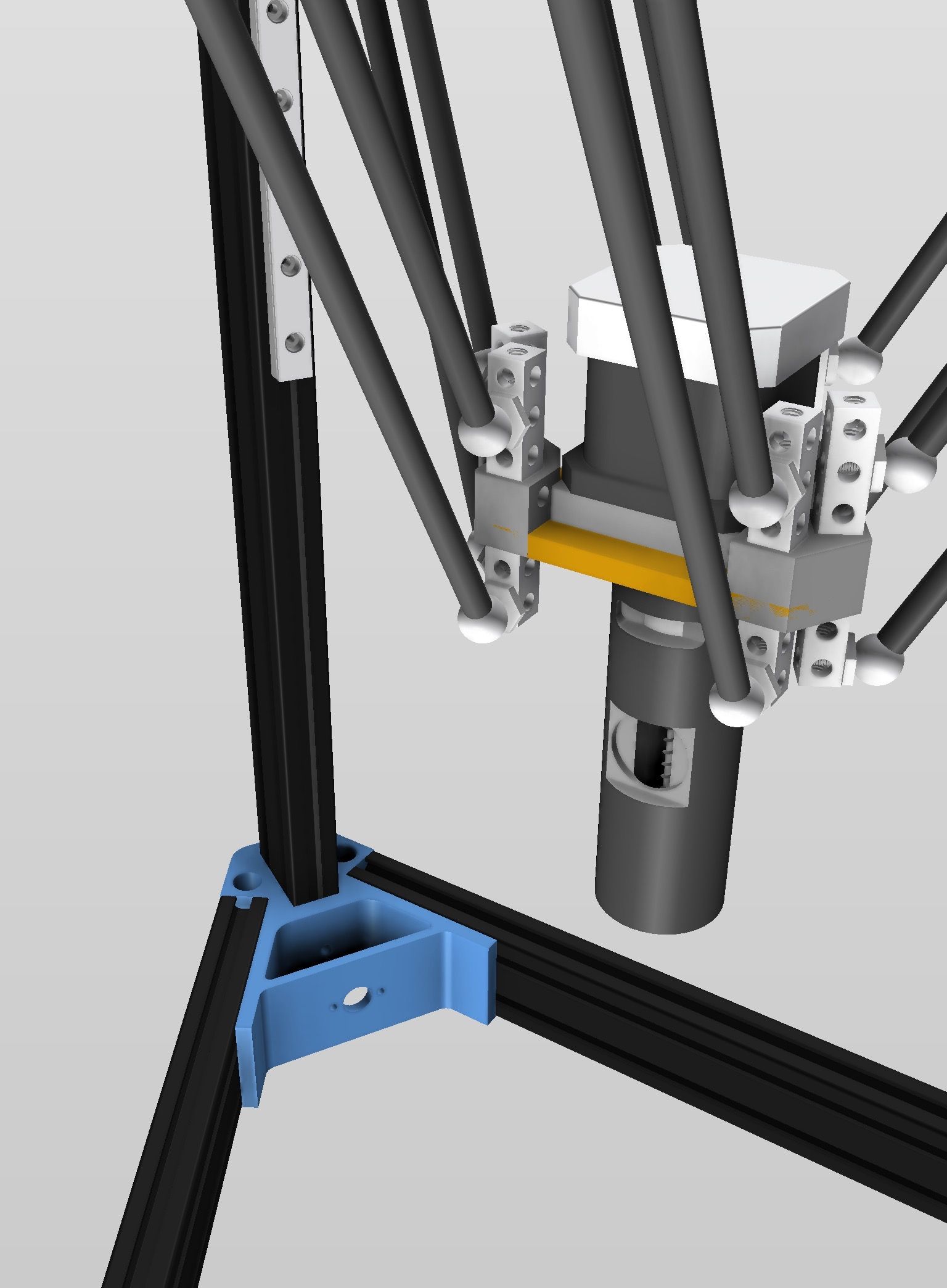
As I'm more and more interested by 5 axis 3D printing, I finally decided to build a 6 axis delta 3D printer. Here is my first draft:
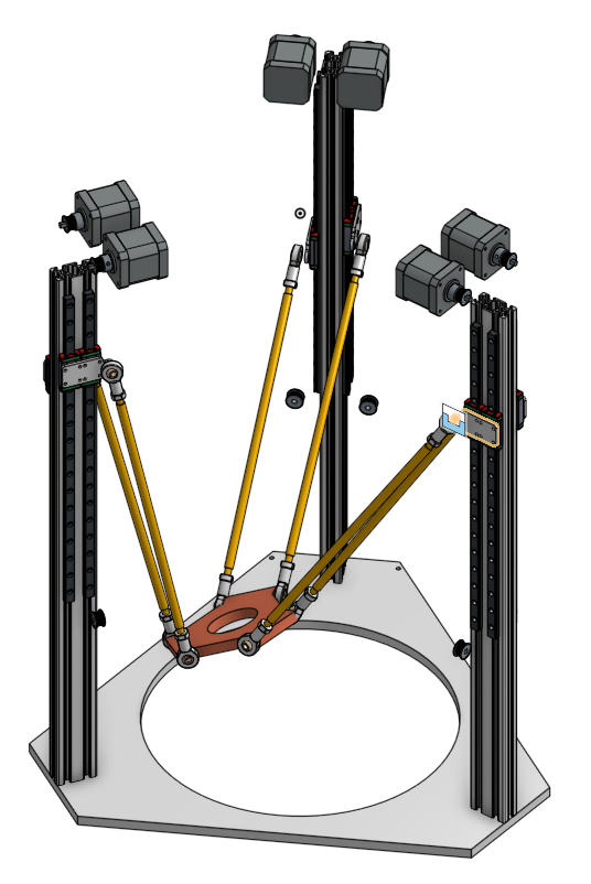
I don't want to spend too much money, but I the same time want to build something decent. So, I think to use cheap linear rails, but use 2 of them to minimize backlash. In this design, the rails are on the same plane, but another solution is to place them at 90° on the profile (this will require 1 profile by axis, which is maybe a better ide for rigidity).
I initially though to use ball screws, but these things are not cheap, and bulky, so I will use belts at first.
The printer will be enclosed to be use as a heated chamber (which will also increase rigidity), and I want to use a direct drive extruder, so I need a good rigidity for the arms and the effector. I don't plan to print fast, but I want a good quality.
I have a few questions:
- what distance should I use between arms? The higher the better?
- what relative length between arms and columns distance should I use? Is it good to have long arms, which remains more vertical, or shorter ones, which go from vertical to nearly horizontal?
- do you know ball joints with large usable angle? Or should I use another design?
Any advice for this project is welcome. I already read the wiki about 6 axis delta calibration, which gives several advices about important dimensions which can't be fixed by auto calibration.
Thanks.
PS: I know that there are no 5 axis slicer yet, but I myself wrote some code to print portions of sphere. And by cloning axis, this printer can run as a normal 3 axis delta without any code modifications.
Frédéric
-
@fma said in 6 axis delta 3D printer:
I don't want to spend too much money, but I the same time want to build something decent. So, I think to use cheap linear rails, but use 2 of them to minimize backlash. In this design, the rails are on the same plane, but another solution is to place them at 90° on the profile (this will require 1 profile by axis, which is maybe a better ide for rigidity).
I have had a good experience with the Robotdigg linear rails on my delta, so I would go for a single rail instead of two.
what distance should I use between arms? The higher the better?
Yes.
what relative length between arms and columns distance should I use? Is it good to have long arms, which remains more vertical, or shorter ones, which go from vertical to nearly horizontal?
The rule of thumb is that the arms should always make an angle of 20deg or more to the horizontal. This typically makes them about 60deg to the horizontal when the effector is centred.
do you know ball joints with large usable angle? Or should I use another design?
Having used two types of ball joint and been unhappy with them, I recommend the magnetic joints by Haydn Huntley.
Any advice for this project is welcome.
- RRF does not include kinematics for a 6-axis delta. They would need to be added.
- To make use of the additional degrees of freedom of a 6-axis delta, you would need a special slicer.
Duet WiFi hardware designer and firmware engineer
Please do not ask me for Duet support via PM or email, use the forum
http://www.escher3d.com, https://miscsolutions.wordpress.com -
@dc42 said in 6 axis delta 3D printer:
I have had a good experience with the Robotdigg linear rails on my delta, so I would go for a single rail instead of two.
Which ones do you recommend? They have several references, and not much informations about relative quality...
The rule of thumb is that the arms should always make an angle of 20deg or more to the horizontal. This typically makes them about 60deg to the horizontal when the effector is centred.
Ok.
Having used two types of ball joint and been unhappy with them, I recommend the magnetic joints by Haydn Huntley.
Do you think they are strong enough to hold an extruder, like Hemera?
- RRF does not include kinematics for a 6-axis delta. They would need to be added.
I hoped you could help me on that part
") Earlier in this thread, you mentionned the fact that forward kinematic is not mandatory...
Earlier in this thread, you mentionned the fact that forward kinematic is not mandatory...- To make use of the additional degrees of freedom of a 6-axis delta, you would need a special slicer.
Yep, as said, I will first use my own Python code to print portions of sphere (I already made some tests, but without head tilting).
Thanks!
-
@fma said in 6 axis delta 3D printer:
I have had a good experience with the Robotdigg linear rails on my delta, so I would go for a single rail instead of two.
Which ones do you recommend? They have several references, and not much informations about relative quality...
I used the 440C ones.
Having used two types of ball joint and been unhappy with them, I recommend the magnetic joints by Haydn Huntley.
Do you think they are strong enough to hold an extruder, like Hemera?
Perhaps not; but I wouldn't consider the Hemera suitable for direct mounting on the effector because it is so heavy.
-
I'm using a hemera on my d300 (with linear rails). it works fine and gets great prints.
https://www.thingiverse.com/thing:4027625
I'm using tricklaser arms which don't pop off like magball arms do. I'd be very hesitant to use magballs and a direct drive extruder.
-
I'm working on designing an effector using a Titan Aero or Hemera with MagBalls. The six MagBalls each have 1.5kg of attraction, so with six of them there should be more than 9kg.
The trick is to have the extruder motor/body above the effector, and the nozzle stick down through it. This way if the nozzle bumps into something, it will have less leverage to knock the effector free. Minimize the vertical distance between the plane of the MagBalls and the tip of the nozzle.
Ultibots used to have an effector with the extruder hanging below it, and the hotend below that. It had problems because the nozzle was a long distance below the MagBalls.
-
One relatively simple algorithm for slicing with a printer using a Stewart platform would be to use a "normal" slicer for everything, except to post-process the output. The algorithm would alter the slicing for the outside layers of the object. If the Stewart platform could tilt the effector by X degrees, then the algorithm would look for places where the outside layer was tilted by less than X degrees, and print that tilted, with the nozzle perpendicular to the surface at that location, thus helping minimize ridged/stepped layers.
-
A possible design for using direct belt-driven carriages for a Stewart platform would be to rotate the 20x40mm vertical extrusions by 90 degrees. Then for each tower, place one motor at the top and the other at the bottom. Place both limit switches at the top. One motor would be on one side, and could drive a carriage using three wheels, which would be carefully designed not to interfere with the other mirror image carriage on the other side of the vertical extrusion. If 20x40mm vertical extrusions make the spacing too tight, then you could use 40x80mm C-Beam extrusions from OpenBeams.
Simple, inexpensive, and quiet.
-
Thanks for all these ideas, Haydn!
About the extruder, I'm already using a custom one, build around a Nema14 scavenged from a geared motor: the output gear perfectly match a BMG gear (clone), giving a 5:1 ratio. And I'm using a FNU as hot-end, which has a long tube, so it is very easy to have the extruder above the effector (I did not plan to do otherwise).
One big issue, though, is the extreme positions of the arms when tilting the effector, bumping in the motor... I think a solution would be to switch to a geared DC motor, as Stratasys use on there printers...
-
@fma said in 6 axis delta 3D printer:
One big issue, though, is the extreme positions of the arms when tilting the effector, bumping in the motor... I think a solution would be to switch to a geared DC motor, as Stratasys use on there printers...
Another crazy solution would be to use a very short Bowden extruder, with the motor mounted on another effector, driven by 3 additionnal motors.
The Delta version of @deckingman monstruosity
Frédéric
-
@fma said in 6 axis delta 3D printer:
The Delta version of @deckingman monstruosity
Let me see you come up with a better way of feeding a 6 input mixing hot end with 6 extruders using 150mm Bowden tubes and which can print at up to 300mm/sec. Then you'll have the right to call my design a monstrosity.
-
@fma said in 6 axis delta 3D printer:
Another crazy solution would be to use a very short Bowden extruder, with the motor mounted on another effector, driven by 3 additionnal motors.
The Delta version of @deckingman monstruosity
I have actually been thinking about doing this for over a year, but I am not willing to upgrade electronics and there are not enough drives on a regular Duet 2 for this crazyness. Also, to give as much clearance as possible between the two sets of arms, I would rotate the 2nd delta setup so the towers sit directly between the 1st setup. This would mean though that you can't really remove large prints from the bed as one of the towers would always block it.
Alternatively, a delta with a ball jointed 4th axis like I have been doing for a while, might be good enough. I am nearing the end of designing something very similar but with two 4th axis rails, joining at (x0, y0) for extra rigidity.
-
@Nxt-1 said in 6 axis delta 3D printer:
I have actually been thinking about doing this for over a year, but I am not willing to upgrade electronics and there are not enough drives on a regular Duet 2 for this crazyness. Also, to give as much clearance as possible between the two sets of arms, I would rotate the 2nd delta setup so the towers sit directly between the 1st setup. This would mean though that you can't really remove large prints from the bed as one of the towers would always block it.
That was my first idea, and I droped it for the reason you mentionned.
-
Does anyone know where I can find 3D models of these Kossel vertex and carriage?
https://www.robotdigg.com/product/555/2040-or-3030-Alu-Vertex-for-Kossel-XXL-or-XXXL
https://www.robotdigg.com/product/495/Carriage-for-open-ended-beltThanks!
-
@fma said in 6 axis delta 3D printer:
Kossel vertex and carriage
Hi @fma, I have the basic vertex models for the Robotdigg 2040 corners in Fusion360 format as was taking advantage of lots of quiet-time with lockdown to learn the product. Let me know if any use. Re the comment above on strength of the magballs/arms - I am just working though doubling up to 12-arms as need to support a Nema17 for my Clay extruder, six arms just about worked but would one would occasionally snap off when starting.
Not the cheapest solution, but I wanted the ease of magnetic attachment as need to remove the extruder for cleaning after prints. Should know in next couple of weeks how it goes.
-
Just to chime in my experience with inexpensive linear rails as another anecdote : The rails themselves were fine. It took some work on the carriage blocks to make the difference over delrin-covered ball bearing solutions I was looking for.
I had to adjust the retaining wires to line up properly for the rails. This was the WORST part since that stupid wire is in the middle of everything and if it's off at all you're popping out bearing balls, rubbing the rail, or not feeding the bearings smoothly, but it is the difference between feeling like a lowish drag slide or a greased up pig in a teflon ice rink. As for replacing the ball bearings * themselves in the carriages and re-greased everything in super-lube which didn't really affect them as much as adjusting the retaining wire, but did make them near silent for me.
Lots of youtube videos on reworking the carriages and why you should at least disassemble/ clean and re-grease them (at least the cheap ones) at a minimum. For the cost, a spare carriage block or two can save you a lot of frustration as well.
- replaced with 3/32" Inch Si3N4 Silicon Nitride Ceramic Ball Bearings G5 Balls, the G5 is important since it's the grade of the bearing, I chose non magnetic materials since I don't want them getting fouled by my magnetic arm mishaps which after removing them into a magnetic tray I'm confident it would have affected their performance.