Duet3D Logo

    Duet3D

    • Register
    • Login
    • Search
    • Categories
    • Tags
    • Documentation
    • Order
    1. Home
    2. lord binky
    • Profile
    • Following 0
    • Followers 0
    • Topics 10
    • Posts 83
    • Best 21
    • Controversial 0
    • Groups 0

    lord binky

    @lord binky

    27
    Reputation
    2
    Profile views
    83
    Posts
    0
    Followers
    0
    Following
    Joined Last Online

    lord binky Unfollow Follow

    Best posts made by lord binky

    • RE: I see no effect of microstepping on torque

      @e4d yeah.... it's not the total torque that changes, it's the torque per step. So simplified you got two coils and we are looking at two teeth on the rotor. Coil A is at full current so it's pulling the full torque into that position on tooth A which is a full step position. A half step will put half current on each coil so you only have half the torque pulling into the middle of the two teeth. Continue to put full current on coil B, and zero on coil A and you get full torque to move you from the mid position between Teeth A and B to the full step position of B.

      Whether you microstep or not you go through full current on a coil in the full step positions so your total torque is the same over a distance, but how well you constantly and repetively hit a microstep outside that full step position decreases as you increase the number of positions between full steps. TLDR; the tiny changes in current may not actually move you that tiny amount between the teeth, but when it comes to the tooth being fully lined up it's all the same.

      posted in Using Duet Controllers
      lord binky
      lord binky
    • Fixed my high pitched fan (electrical) noise

      So I have a super annoying high pitch whine on a pair of Sunon 12v fans (MF25101V1) in a push/pull on a mosquito clone. While I'm replacing the hot-end heater I figure it should be an easy thing to either fix or identify why my fans have this high pitched induction coil whine that slowly claws at your soul. Might as well fix while things are torn down... and into the rabbit hole i dove. Threw my scope on it since I felt like it was some electrical noise was carrying through to the fan motors. Of course I did, I'm using switched mode supplies. Regular 12v rail had all kinds of electrical noise at 500Hz, 1kHz, and 100kHz.

      Well, somethings causing it right? Let's start with filtering some culprits out. I try a capacitor to filter it... nothing. Ok well, a temporary voltage offset on the noise but the waveform didn't change at all? Fine...grab a toroid and do a simple choke...scream.. multiple LC filters ...and still no response...Am I a ghost now? WTF is this sorcery?!

      So eventually I snip a fan out and blissful silent air flow... So it turns out that the issue was running two fans off the same cable right up to their own leads... Noise is gone soon as each fan gets it's own wires back to the terminal strip (they're wired always on).

      I'm just happy the noise is gone and won't question why I've never had an issue wiring this way before. Still I thought I'd share in case someone has a whine / high pitched noise they can't get rid of, then here's one possibility.

      TLDR; Parallel DC Fans sharing a power cable can cause high pitched feedback sometimes, intermittently, and in just the right way to test your sanity.

      posted in Duet Hardware and wiring
      lord binky
      lord binky
    • Sharing my Delta bed.g spreadsheet

      Here's the three versions I when changing my bed.g for my delta printer. They use 32 points and it generates a column that I can cut and paste into my bed.g It works for me, my calibration runs in the 0.01 mm range. Feel free to make a copy and do whatever you want with it, I'm just sharing in hopes of it being helpful to someone. Please watch the printer carefully until you're confident it's working for you, while it works for me I'm just throwing it out there to help and don't make any claims to it working flawlessly although I can't see how it'd go bad if you use values reasonable to your machine.

      Variables to change are:
      -bed size (the outer ring of probe points)
      -Calibration Factor
      -Oversize factor (only on the oversized one where I use it to dial in my arm lengths)

      The first one is my default arrangement
      12 points at the bed size distance (perimeter), 12 more at 2/3 the bed size distance, 7-points at 1/3 and one for the center.
      https://docs.google.com/spreadsheets/d/1trfFyw2LqvRUeq3WPKtEaKaRGZOVwk4034zErVPo3jE/edit?usp=sharing

      The second arrangement I get better calibration numbers from
      16 points at the perimeter, 12 inside (2/3 distance), and 3 points (1/3 distance) and a center point
      https://docs.google.com/spreadsheets/d/17S-CsZrUSqeNFooCKBznFLhmKTVUeivGca3umMWm86s/edit?usp=sharing

      The third is what I use to test / calibrate my arm length. I calculate the oversize factor as the distance to just inside the maximum bed radius over the bed size parameter that I can test within the limits of the towers. Please be careful and watch closely if you use this one.

      https://docs.google.com/spreadsheets/d/172jtcU9UQyQi1yUPvm9tagQ7Fl1T8Yxcv_s8HN2PATI/edit?usp=sharing

      I will try to update if there is a major flaw, otherwise please treat it as a starting point for you play with generating your own test points.

      posted in Tuning and tweaking
      lord binky
      lord binky
    • RE: Best Choice of Motor for a Delta Printer

      @ignacmc

      Ok, here's some pics. The first is an example of the setup. The others show thickness, the needle bearing you have options depending on the surface of the motor face, the ball bearing set while the ID being the same as the motor shaft is nice i prefer the needle bearings for contact area against the pulley.

      20220425_190447.jpg

      20220425_190319.jpg

      20220425_190034.jpg

      20220425_190142.jpg

      posted in Duet Hardware and wiring
      lord binky
      lord binky
    • RE: Inductive Z Probe Settings

      depending on the repeatability you want, you may want to slow the feedrate which is really because of the worst part of inductive probes. Most inductive probes switch at 500hz until you you break the ~$60 retail price point for industrial sensor to get 1khz to 3 khz ( next price point is like ~$150+ and specs can get to 5khz). So the faster you're probing the larger the distance variation between trigger intervals. i use a ie5390 i grabbed off of ebay for like $30 and it operates at 1khz and i go with 60mm\min to get .003mm repeatability which is only a microstep and it levels (delta printer) to .01mm over a 300mm probe area

      posted in Tuning and tweaking
      lord binky
      lord binky
    • Extruder cable shielding improved surface finish (slightly).

      Long story short, all three axis stepper motor cables are shielded (EMI mesh sleeve) on my delta printer (although this could apply to any style) so I skipped doing it on the extruder. Half-assing it bit me again and it may be what got rid of the irregular surface ripple that kind of looked like a salmon skin/moire pattern that you only really see when the surface is glossy. Yeah, that really fine one that drives some of us crazier than massive ghosting does. Until this point I had no indication my electronics had any glaring issues and wrote it off thinking I had that well in hand. I just glared at the delta my mechanics blaming them as the source leaving me completely stumped for what the real cause was though. Anything that seemed a plausible mechanical source I reached out to fix hoping it would be the thing to remove those tiny artifacts even though it didn't match up with anything obvious math wise.*

      I discovered this while I was playing with the new input shaping plug-in. My hotend fans are normally always on and I unplugged them while using the accelerometer to decrease the noise level on it. Then while toying with the plug-in I heard extruder noise that was almost a whine that I couldn't hear over the hotend fans. I noticed it while homing and then dead quite after homing was done made it stand out though. So I homed again and reached over to feel the motor, and it's vibrating with some oscillation when the axis motors are going. I just sat for a minute with my face in my hand and wishing I could give past-me a slap to the back of the head for stopping 3/4 of the way through on shielding the motor cables. I wanted to share my success on this in case it can help anyone else frustrated with calming the waves in the specular reflections even if it is also a facepalm moment of shame.

      *- That isn't to say there aren't other things causing it in another build. I just have happened to already done my best to mitigate them in previous rabbit holes on belts, pulleys, eccentricities on anything round and rotating, arm lengths, arm joints, arm spacing, then arm rigidity, all the extruder bits, fan vibration, frame vibration, bearings (both the linear slides and stepper motor bearings), chasing this stupid pattern.

      posted in Tuning and tweaking
      lord binky
      lord binky
    • RE: Choosing correct motor for Delta

      @Danal I use the same Motors on my Rostock max for years now and they've held up quite well for the abuse I did on them. I have looked for lower inductance / inertia 0.9 steppers with good torque but I haven't found one I'm confident will perform better for a decent price (I'm looking at you moons' industries...)

      If you get a chance, test out my settings I scope tuned for the motors. Mine run 1500ma without getting hot and are as silent as I can expect of them.

      https://forum.duet3d.com/topic/13028/my-tuned-tmc2660-settings/2

      posted in Duet Hardware and wiring
      lord binky
      lord binky
    • RE: 3 spehre/point Delta ("Spiderbot")?

      You can get the mathematical differences with one of the calculators ( i like the openscad simulator). The optimal arm spacing is dependent on your print diameter, but you also have a trade off with printable area since you'll have to move the balls further from the center of the effector. Since you can't really go further than having the joints be over lapping, that's kind of the concept to ride that optimal point at least math wise. As for how it works out in practice, not clue but there's so many little variables in the whole system that I don't see it helping that much when there's enough knowledge about the normal configuration you can easily tease out what is probably off when your troubleshooting.

      posted in 3D Printing General Chat
      lord binky
      lord binky
    • My tuned tmc2660 settings

      Following the trinamic tmc2660 manual and spreadcycle guide I busted out my o-scope with a current probe and a helping hands on the sense resistor. The motors I tuned were Wantai 42BYGHM809 and a PG35L-048. I run a delta, and my steppers are running at 1.5 out of the specced 1.7A and they are staying significantly cooler than when I tuned by ear and they are behaving much better for me, it even got my past the .02 bed leveling barrier I was at.

      Anyways, thought I'd share my efforts in case it might help someone.

      Wantai 42BYGHM809
      M569 P0 D2 F2 B2 Y01:09:02

      PG35L-048
      M569 P3 D2 F3 B3 Y03:07:02

      posted in Tuning and tweaking 42byghm809
      lord binky
      lord binky
    • RE: Question: Recommendation for mechanical endstops

      I prefer the contactless approach and just wire in (directly with no extras has worked fine for me) A3144 digital hall effect sensors (~$1 ea.) for my endstops and slap a magnet on the moving part. You can home fast and do a slow back and return and the repeatability has been hands down better over time than contact switches I've tried.

      posted in Duet Hardware and wiring
      lord binky
      lord binky

    Latest posts made by lord binky

    • RE: Delta bed leveling issues

      Oh man, I've chased that delta printer backlash down to ~0.05mm on my rostock metal max. I stopped chasing it after it got that low since it gets harder to identify the source the smaller the backlash gets.

      posted in General Discussion
      lord binky
      lord binky
    • RE: Is it in the belts or stepper motor?

      @norder Good Idea, I'll double check that this weekend, it's the same for each tower, there's a flat on the motor shafts and I have 2 screws on the pulleys, so it's probably not loose. Admittedly not the same as definitely not lose, and I've gone down rabbit holes overlooking simpler things than that.

      posted in Tuning and tweaking
      lord binky
      lord binky
    • Is it in the belts or stepper motor?

      So I was about to keep chasing down rigidity in the arms of my delta printer and started poking around to see what else could have play in it. Linear rails, ball ends, arms are all really rigid, you tap on the carriage with your finger nail you feel it in each of the carriages like it was solid. Nothing stood out as a "wiggly". But then I realize I can move the effector, it returns to the same point, everything's connected well but there's play? I test it by using probing distance for reference. Turns out I can wiggle the effector over .5mm and even then unless I feel motors skip a step, the impact on the z probe is from 0.247 to 0.266. So outside of skipping a full step, it might (and usually did not when I was toying with it) mess up a microstep. So it's a spring like motion up to at least .5mm that returns effectively to the exact same spot. I feel around again, pushing on the effector even a slight bit you feel a corresponding movement in the belt up by the idlers. And this has me stumped, because nothing improves tightening a belt so it's not loose belts.

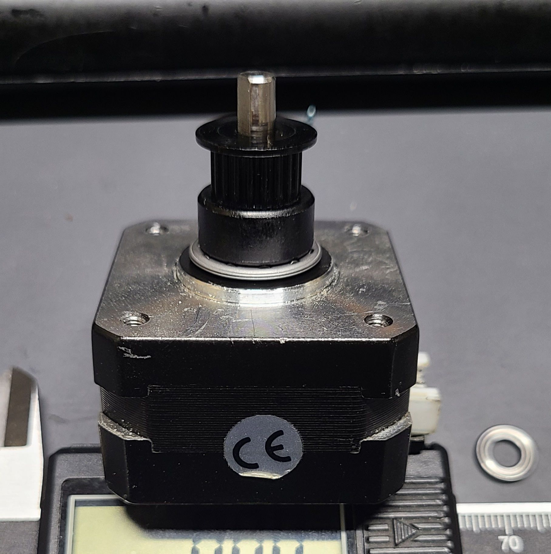
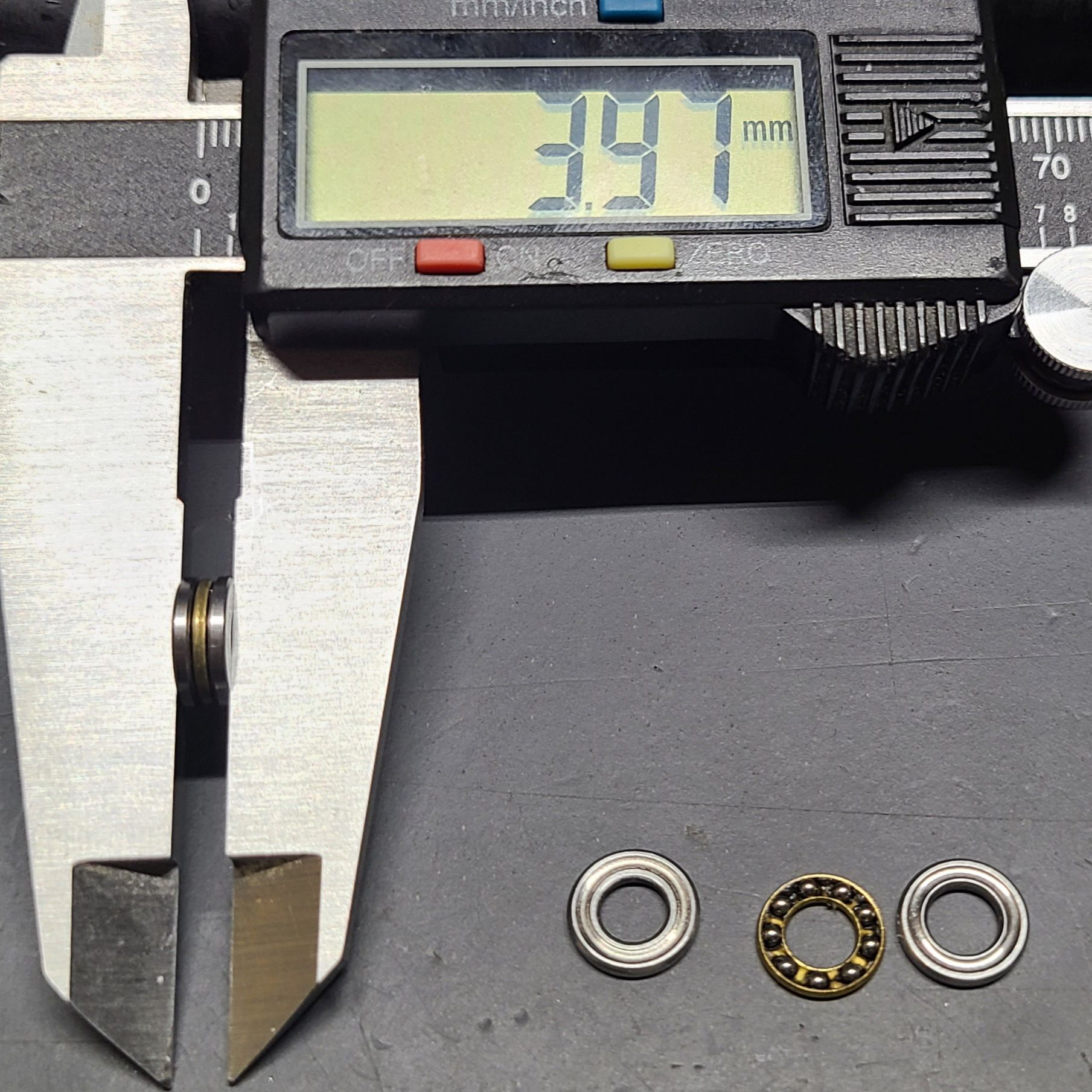
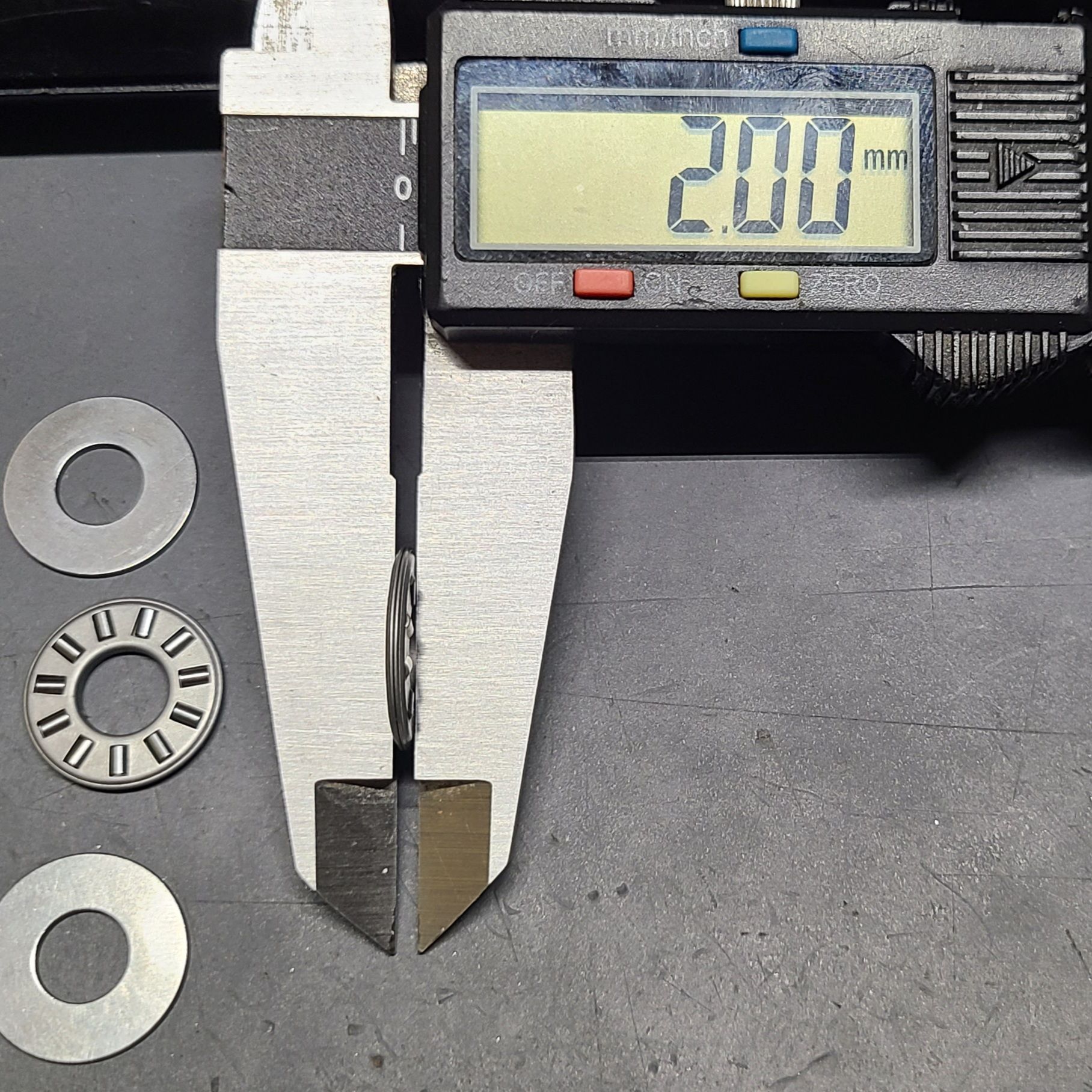
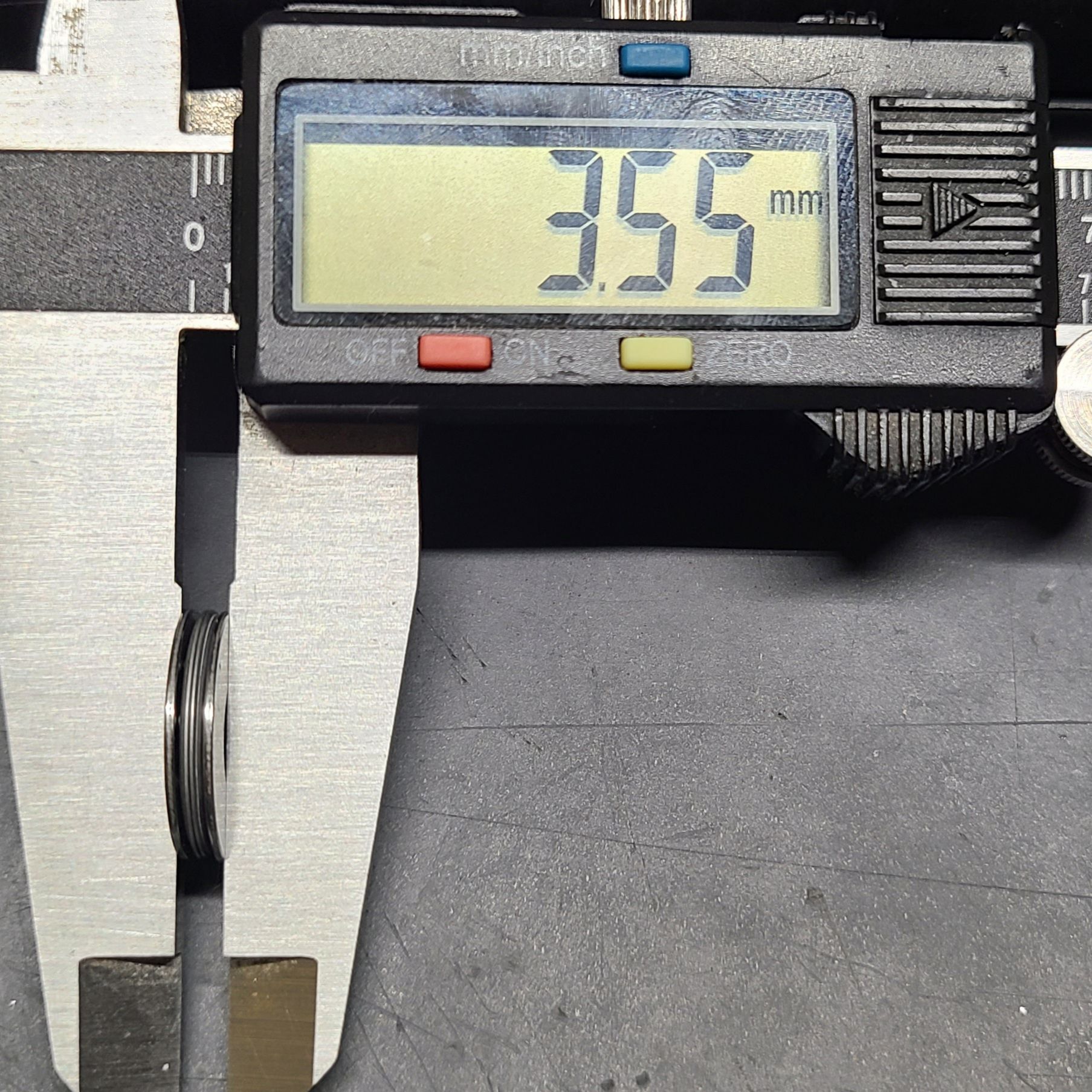
      I feel like if I can address whatever "play" in the effector this is it would seriously help out on ringing. My gut says it is not in the belts, but it wouldn't be far fetched to say 9mm belts vs 6mm belts just don't do that. I feel like it is the stepper motors that are behind that movement, but I'm using 0.9 2.4A Nema17's ( Wantai 42BYGHM810) @ 2.4A. The play is not originating from the stepper motor shaft flexing (I have bearings stopping that).

      I really like the performance I get from them otherwise so I'm stumped if I'll actually eliminate this flexible movement changing to a NEMA 23/24 and just taking the hit on motor specs (these ones have like 1.8mH inductance, nice for speeds on 24V). Would I have to go to closed loop steppers that'll actively counter that flex, but I'm not sure it'd even register since everything returns to normal after pressure is removed. And to rub it in, I feel like even if it's in the belts or steppers, how is this not prominent in those speedy CoreXY builds, they have long lengths of belts like my delta and nema17's (I think) are common components for them. Or is that just overlooked because it disappears when you go full servo.

      My only options left in the sytem for the source of it is pulleys, belt, and stepper. I suppose pulleys could be the other issue, I don't have much for options on one half but I could swap idler pulleys to a large diameter and use a deflector pully to keep everything lined up. I'd love some input.

      posted in Tuning and tweaking
      lord binky
      lord binky
    • RE: Flsun Q5 delta printer, poor dimensional accuracy

      @dog said in Flsun Q5 delta printer, poor dimensional accuracy:

      Decided to go with altering the rod lengths, because that seemed to work and I kinda understood how it affects the print when it comes to dimensions. (measured length / desired length * rod length = new rod length ish) basically if the print is too small, shorten the rod, if too big, lengthen it.

      I've used a piece of carbon paper over a piece of paper and did a heated nozzle tap (takes less force to mark) to do basically the same thing. It can speed up the process without doing a full print and having to account for anything other than just movement simply measuring from the outside of one dot to the inside of the other.

      posted in Tuning and tweaking
      lord binky
      lord binky
    • RE: Help on custom Delta printer build

      If your making your own arms, I did a test (yes i haven't shared it before now but i had another trick up my sleeve i wanted to test out and grab comparison data from the accelerometer) and got improvements on ringing/ on 360mm arms by reinforcing them midway. It does not affect the arms as long as the articulation is centered on the arms.20220713_181028.jpg

      posted in 3D Printing General Chat
      lord binky
      lord binky
    • RE: Help on custom Delta printer build

      @yiannis i used the openscad delta simulator to maximize my stability for my delta over the print area when designing the parts : effector carriages, and arm spacing. The frame is a rostock max metal, and the arms are 360mm haydn magball arms. I did get improvements in my printer optimizing for stability so it's what i'd recommend using for any variables you don't have locked down.

      posted in 3D Printing General Chat
      lord binky
      lord binky
    • RE: Bed leveling using strain gauges as endstops/probes

      I used the FSR and johnsl board on my delta for awhile and it did pretty well after working out some kinks in my mounting. Mapping a bed for delta autocal isn't so great since there is some deviation in response simply since the force varies between 3 sensors based on where you touch, but for leveling it was more than sufficient. Main reason i went contact-less on any sensor i could. Using a brass nozzle to touch the bed would deform the hole eventually, enough to irk me on a calibration cube (well, immediately if i crashed as you'd expect). The johnsl board would likely do great on sensitivity if the fsr's weren't loaded by a weight like the bed depending how you arrange it too.

      posted in General Discussion
      lord binky
      lord binky
    • RE: Best Choice of Motor for a Delta Printer

      I'll also add for me if you exclude bearing issues in motors or pulleys (I've blown the tiny bearings in idler pulleys multiple times which is why i used flanged bearings now). The next issue of high belt tension is going to be eating up the belts and teeth when your hotend or carriage eventually crashes. I think it's easy enough to tension a little more and recalibrate starting low and then go high until nothing improves.

      posted in Duet Hardware and wiring
      lord binky
      lord binky
    • RE: Best Choice of Motor for a Delta Printer

      @ignacmc i just push the carriages all the way up and tension to an equal frequency using an app. I ballpark the base tension at the idler pulley for tight but not too tight and tune from there. You have a lot more wiggle room than you'd expect, just make sure they're the same.

      I've been using deltas for years (my first was a the seemecnc rostock max v2) and I've found it isn't as necessary to hit a specific tension than it is to just maintain a reasonable and equal tension on the towers. I've done all sorts of gauges and tricks for targeting a specific tension and it just hasn't mattered. That goes for pretty much all aspects of a delta though, carriage resistance, arm lengths, rod spacing, etc. The more each tower responds the same the less weird stuff you chase and are able to compensate with a setting change in software for or identify the root cause like joints.

      posted in Duet Hardware and wiring
      lord binky
      lord binky
    • RE: Extruder cable shielding improved surface finish (slightly).

      So i couldn't recreate the issue with another cable..Frustrating when trying to show shielding fixed the issue, but I'm still confident that was what helped...mostly. Still, I had another test print showing what i have moved away from when EMF was an issue regardless of the solution ( cable pathing or shielding). I adjusted contrast so the visibility was clear even if the colors are looking a little artificial. The surface issue was apparent in any print with the outer layer lower than 60mm/s.
      20220423_200324.jpg

      posted in Tuning and tweaking
      lord binky
      lord binky