Clearpath Servos with 1XD Expansion
-
@dc42
Absolutely:
I removed Homing from the gcode file, but I dont have a start,stop, or cancel.ghere is the console text, there was one instance where I didnt do a G1 X0 Y0, but you will probably see that. It looks to me that the 1XD boards are receiving and sending commands correctly. please verify my observation. console.txt
Here are the current ratings of the clearpaths:
5 VDC - Min 8 mA
12 VDC - Min 9 mA
24 VDC- Min 12 mAll of the pins are rated at 10ma/Pin, what is the max of the 5v common?
If that sink current is limited by a resistor its very possible that we could be under 8ma@5v if using a 5% @ tolerance resistor @ 10ma Max per pin.
@Teknic_Servo any info you can add to this?
-
Thanks for the info. It looks to me that board 40 and 41 report drive positions 1000 and -123388 respectively both at the start and at the end, which is what I expect if the commanded start and end positions are the same and there have been no homing moves in between that could reset the origin.
If the Clearpath drivers draw 8mA at 5V, that's similar to a resistive load of 620 ohms. I'll verify the 1XD output voltage with 620R load resistors. In theory the step and direction outputs should provide minimum 4V typical 4.5V with a 20mA load.
-
I've checked the outputs from the 1XD board with 620 ohm load resistors, using your configuration (M569 P40.0 S0 R0 T2.7:2.7:2.7:2.7):
- The signal amplitude is 4.8V
- The step pulse width ls never less than 4.1us
- The smallest interval between step pulses I saw was more than 100us
- The end-of-step-to-direction-change hold time looks consistent at 8us, however direction changes are not very frequent so it's hard to be certain that there are no shorter ones
- The direction-to-step setup time appears to be very long indeed
Here's an example of a step with a direction change afterwards. The 'scope is looking at the STEP- (yellow) and DIR- (blue) output pins of the 1XD, with the 620 ohm load resistors connected between those outputs and the common +5V output.

PS:
-
The voltage across the 620 ohm resistor connected between Enable- and +5V is a little lower, 4.78V. This is expected, because that pin is not driven by a high current drive pin of the microcontroller. But it should still be enough, because few device providing 5V output signals would provide more than that.
-
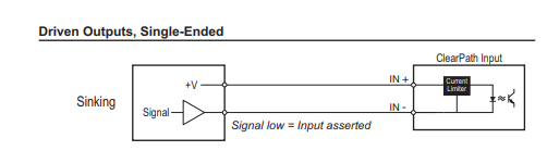
Please confirm that you have connected the ClearPath A+/B+/Enable+ inputs to the common +5V pin on the 1XD board, and the ClearPath A-/B-/Enable- inputs to the individual output pins.
Duet WiFi hardware designer and firmware engineer
Please do not ask me for Duet support via PM or email, use the forum
http://www.escher3d.com, https://miscsolutions.wordpress.com -
@dc42 correct I have all positive pins connected to the 5v on the header with the dir, step, en pins. And those pins are directly attached to the servos.
The clear path manual does mention 5v minimum for the inputs and also states that less than that may work initially but will eventually not. I'm thinking the less than 5 volts is the issue here.
I mentioned the currents because the 1xd page mentions that they can only sink 10ma, and I assume that is through a 500ish ohm resistor. If that resistor is a 5% tolerance that would put the max current bellow 8ma.
-
I really don't think the voltage is the issue. There is no 5V level driver that really does supply the full 5V. A voltage drop of 0.2 to 0.4V is normal.
OTOH I understand the bit in the manual about not using differential drivers, because 5V differential drivers typically put out between 3V and 4V.
The STEP and DIR outputs of the 1XD can sink 20mA, and do not have a series resistor.
-
PS - you may wish to check the voltage across the Enable and DIR inputs of your servo drive, to check that there is nothing wrong with the 5V regulators on the 1XD boards.
Duet WiFi hardware designer and firmware engineer
Please do not ask me for Duet support via PM or email, use the forum
http://www.escher3d.com, https://miscsolutions.wordpress.com -
@dc42 ill check them when I get off work today, and I'll probably shoot teknic an email since they state 5-24v for signals and get their input.
I assume the 5v regulator also provides power to other ICs on the board?
Would it be possible to bodge a simple board that sends 12-24v to the servos and use a resistor divider back to the 1xd?
Is the 1xd schematic available yet, or will it be?
-
Here's the 1XD prototype schematic. We plan a few minor changes for the production version.
Duet WiFi hardware designer and firmware engineer
Please do not ask me for Duet support via PM or email, use the forum
http://www.escher3d.com, https://miscsolutions.wordpress.com -
4.99v on 40
4.97v on 41 Likely due to the R18 and R20 tolerances.Did the same test with the servo encoders with the following results:
RAS 6.2	RAS 6.2
3600 pulse/rev	3600 pulse/rev

Servo Encoder at X0 Y0		Driver board position at X0 Y0
A	B	                B41	B40
-12564	23112	               -49695	13499
-12289	23124	               -49695	13499
-12031	22945	               -49695	13499

no change with or without RAS
Unless you have any other ideas I feel like the Clearpaths are not compatible with the 1XD board for some reason, Ill contact Teknic to see what their thoughts are.
-
After more research I have found multiple instances where Clearpath Servos are very picky about the signal voltage. Ive designed a small level shifter board and sent it off for a prototype run, I hope to have it in about a week or so. I will be shifting the signals to 12v.
Once the boards and components arrive Ill test the boards, then test them with the servos and ill update.
-
@jballard86 Did you manage to find a solution? If you did what did you change?
-
@dc42 @jballard86 Either of you ever figure this out yet? i just setup with 2 clearpath servos i see 0 hiccups but the layer shifts are real! i'm on version RRF 3.2 via duet3 + Pi4 SBC.
-
For others who find this thread: I just installed beta 3.3 and it's working correctly now, looks like root cause was in can communications.
-
@dop and @jballard86 . Have any of you managed to produce a good looking print yet?
if yes What were the T timings you ended up using?Best regards
John Henrik Bergene -
@dop I fixed it by abandoning it and going with a different hardware solution. My assumption after lots of trouble shooting is that the clearpaths en/stp/dir signals needed to sink more current than the 1xd could provide, or that it was a CAN issue. I ended up developing my own board that worked flawlessly.
-
@dop said in Clearpath Servos with 1XD Expansion:
For others who find this thread: I just installed beta 3.3 and it's working correctly now, looks like root cause was in can communications.
If it was an issue in CAN, id assume that issue has been in all of their products that utilize CAN. its unfortunate that they left bugs like these in their code for so long unnoticed.
-
@jballard86 I am currently embarking on a project implementing the ClearPath SD servos with a duet 3 and 1XD and was wondering if you would be able to provide any wiring advice or images? I've followed the documentation as best I can for wiring the step/dir/en to the 1XD with no luck and this post is one of the very few demonstrating exactly what I am attempting to create.
-
This looks like all you should need for wiring information and timing.
However I don't believe the original poster got these servos working correctly. (I may be reading it wrong.)
@dc42 said in Clearpath Servos with 1XD Expansion:
I've checked the outputs from the 1XD board with 620 ohm load resistors, using your configuration (M569 P40.0 S0 R0 T2.7:2.7:2.7:2.7):
- The signal amplitude is 4.8V
- The step pulse width ls never less than 4.1us
- The smallest interval between step pulses I saw was more than 100us
- The end-of-step-to-direction-change hold time looks consistent at 8us, however direction changes are not very frequent so it's hard to be certain that there are no shorter ones
- The direction-to-step setup time appears to be very long indeed
Here's an example of a step with a direction change afterwards. The 'scope is looking at the STEP- (yellow) and DIR- (blue) output pins of the 1XD, with the 620 ohm load resistors connected between those outputs and the common +5V output.
PS:
-
The voltage across the 620 ohm resistor connected between Enable- and +5V is a little lower, 4.78V. This is expected, because that pin is not driven by a high current drive pin of the microcontroller. But it should still be enough, because few device providing 5V output signals would provide more than that.
-
Please confirm that you have connected the ClearPath A+/B+/Enable+ inputs to the common +5V pin on the 1XD board, and the ClearPath A-/B-/Enable- inputs to the individual output pins.
SeemeCNC Rostock Max V3 converted to V3.2 with a Duet2 Ethernet Firmware 3.2 and SE300
-
This post is deleted! -
Any update on this? Did anyone get their setup working?
I saw Pantheon Design is using clearpath on their new printer but it sounds like they created their own hardware to use duet/clearpath.Thanks