Battling sources of vibration and noise
-
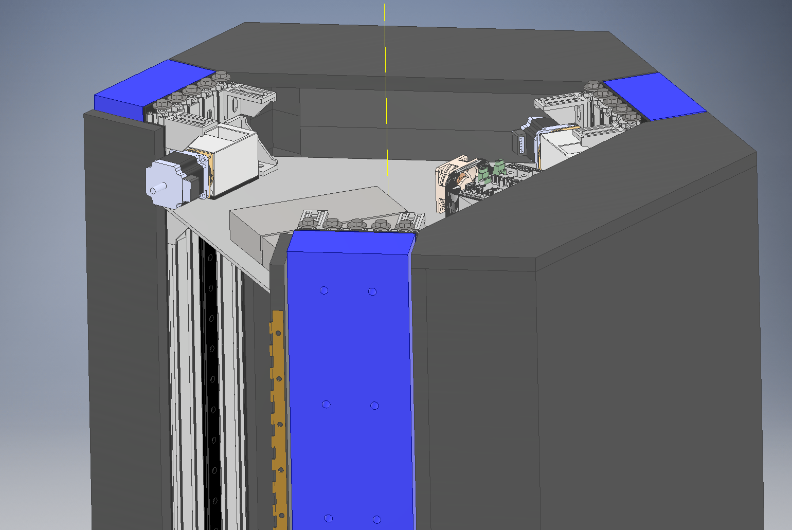
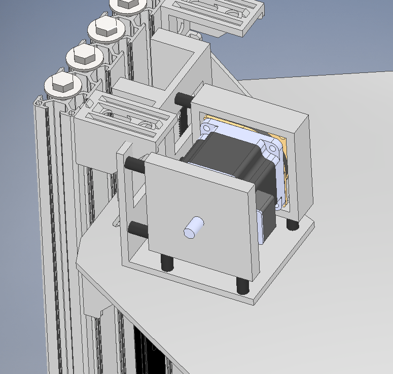
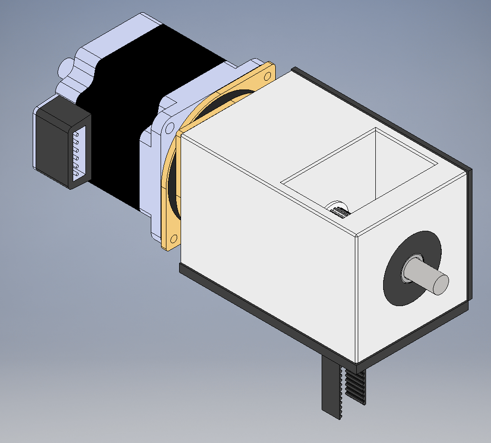
@arhi @theruttmeister The thing is it does not matter whether in what conditions my leadscrews are, because I don't have any. Aha! My machine is a delta, so just belts driving linear rail sliders. Here's a see through view of the motor bracket as I envision it now (and am printing at the moment) and a more overview-y pic of the top of the machine.
I did end up ordering the cheap jaw/spider couplers I linked earlier. I hope the spiders in them are not sloppy, causing a lot of backlash. They should have arrived today, but I have a feeling the shipment will be delay until tomorrow at least.

-
@Nxt-1 said in Battling sources of vibration and noise:
The thing is it does not matter whether in what conditions my leadscrews are, because I don't have any.
in your case the shaft secured between two bearing is what needs to be straight and in that case that "cross/web" coupler works awesome. I never had issues with them having any backlash even on a milling machine. The plastic cross in the middle does ware out on the milling machine and develop some backlash (after many hundreds of hours working) and then you replace it (just the plastic part)
-
So today I received the couplers and they look and feel actually quite decent. I installed them on the brackets from my last post, put the bearings in their new rubber sleeves and installed those as well. I took the new assembly for a spin on the machine and the noise was actually considerably worse believe it or not.
After trying out some different combination of rigid couplers, flex couplers, old brackets and new brackets, my conclusion is that the rubber sleeves around the bearings are a bad idea. I have some long time sensitive prints I need to get done so right now I am running the old bracket with the new flex couplers.
I am not really sure where to go from here. I might look into doing something like the double belt arrangement like @arhi mentioned earlier.
-
I use sorbothane (there's various brand names) whenever I need to kill vibration from parts contacting. It actually performs best when slightly compressed as well. This works great for audible noise, but on my delta with dampeners (and bearings to relieve motor shaft tension) I didn't see any visible improvement on my vertical rippling when I applied it any place I could.
I was using a E3D titan extruder (0.9 deg stepper, 16 microstep interpolated) and fine adjustments to that showed some improvements, but moving from a direct drive to a flying extruder resolved all the vertical banding that was left that I was seeing.
-
@Nxt-1
If I had to guess, the rubber is too hard.The tensioned webbing is worth a try though.
-
I just did a quick-ish mockup of how I understood what was suggested by @arhi earlier.
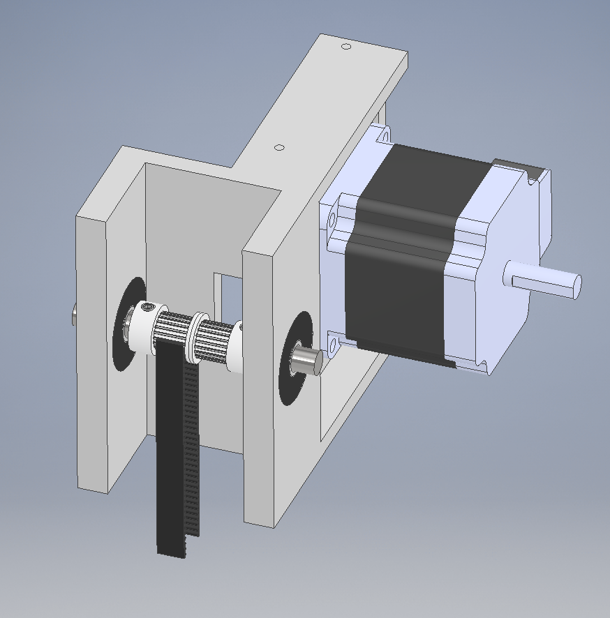
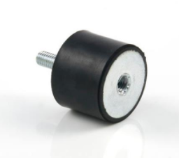
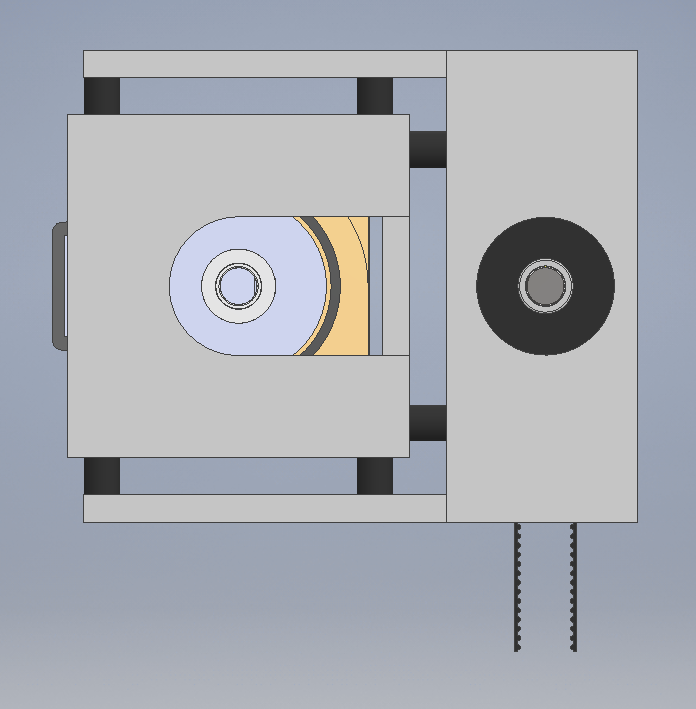
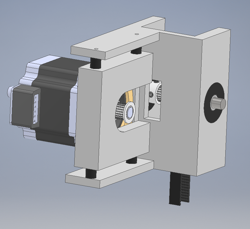
All the dark black solids you see are made of rubber. In this configuration, the bearings supporting the intermediate shaft are mounted in the thick rubber washers again. The motor is mounted to the same Astrosyn style face-dampers that I use now. A printed squarish part is bolted to the other side of those dampers. This that part is in turn supported by 6 type B circular dampers.
What do you guys think, there for sure is a lot of rubber in there. I did not go for any rubber sheeting or something like Sorbothane, because is't certainly not cheap and I don't have great (fast) sources for those at the moment.
-
@Nxt-1 I'd look at adding support to the back end of the motor. I would most likely mirror the front motor mount, utilizing the two mounts on the bottom and the two mounts on the side. For initial testing I'd leave off the entire top set as I think it might over-constrain - but it all depends of the hardness / elasticity for the items your using.
Since you're looking into this configuration, it is worth noting that changing the drive ratio will effect the resonate frequency, as well as steps per mm. Might be fun, and worth a shot, to play with it. -
-
@Nxt-1 dunno if the rubber housing for bearings holding main shaft are necesary and if they will add ringing or not.
the motor in this configuration is normally on the dumpener, so there is rubber between motor and that bracket so none of the motor vibrations are transfered to the frame directly
-
First of all thank you all for the replies, nothing excites me more then waking up in the morning an seeing 3 new post haha
@Kolbi Any specific reason to further support the back of the motor? I can think of two possible reasons. One, to counteract the moment loads due to belt tension and second to try to reduce vibrations from that side. The issue with constraining the back side is that I lose the effectiveness of the face damper I believe. And I don't have a second set of face dampers at hand sadly
 Love to hear your thoughts.
Then again, I might lose the top dampers as you said (I need some vertical space anyways to fit in the machine) and move them to the back.On the topic of changing drive ratios, yeah it nice to have the option. Although I must admit I am not sure if I'd want to really change it up. Going with a lower steps per mm get me into trouble with back emf and going the other way I lose resolution. 'They' got me cornered

@theruttmeister It sure is a lot

@arhi Good point, seeing how my last attempt at using rubber for those bearings went, I might try a rigid mount first.
-
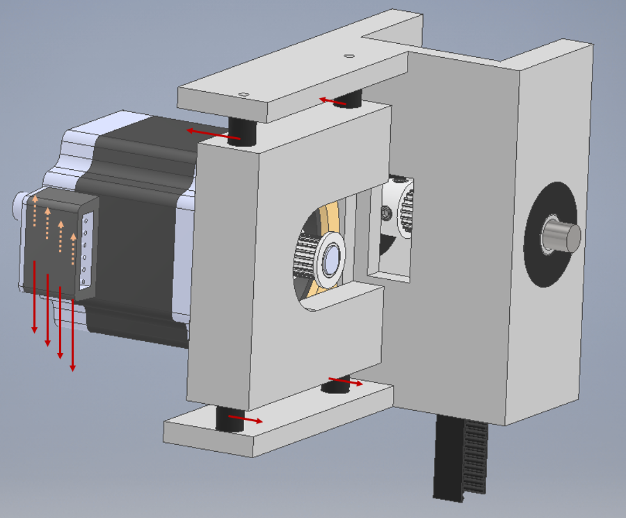
@Nxt-1 IMO, the shown configuration, the top, and bottom mounts will have constant shear stress, which will lessen their effectiveness and in this case, might cause more vibrations to resonate as the back end of the motor is unrestrained, and will shorten the lifespan. I would move the two mounts from the top to the rear-bottom of the motor. Of course, the hardness of these mounts is unknown to me, but this is just general.
Also, with the configuration, it gives you the advantage to easily change the drive ratio. If more vibration/noise is experienced at slow stepper motor speeds and lessens at higher speeds, you could change the drive ratio which could reduce the over/undershooting from the driver-motor arrangement.
-
@Nxt-1, I think you're using f360? I am no expert in f360 but you could try to perform a stress analysis of the part.
https://www.youtube.com/watch?v=LBZAH5RMR2c -
@Nxt-1 On changing the drive ratios, you could leave the ratio the same, but still change some of the pulley teeth numbers. I'm thinking keep the motor pulley the same, but go up a size or two on both pulleys on your idler shaft (and the one at the bottom of your tower). My understanding is that larger pulleys operate more smoothly as the belt is pulled round such a tight radius.
It might also help distrupt any belt meshing interactions that might be causing your NVH issues? I'm particularly thinking of your findings with the idelr at the bottom of the tower.On a different note (and sorry if I'm digging up old ground here...), I read another post recently where DC42 mentioned that Nema23 motors are typically more susceptible to noise issues than Nema17's. I think you'd previously mentioned that you didn't want to go back to smaller steppers, so not sure how useful it is, but I thought intersting to know
@dc42 said in Massive Vibrations with Duet3 & NEMA23 drives:
What I think I said, which was based on something I had read elsewhere, was that when designing a stepper motor there is a balance to be had between smoothness of microstepping (i.e. how consistent the size of each microstep is) and torque; and that Nema 17 motors were typically designed to favour smooth microstepping, whereas Nema 23 motors were typically designed to favour maximum torque.
All stepper motors suffer from mid-band resonance, which is caused by the inherent elasticity of the magnetic forces combined with the rotor inertia. However, mid-band resonance tends to occur at travel speeds, not printing speeds.
-
@engikeneer said in Battling sources of vibration and noise:
as the belt is pulled round such a tight radius.
yes, larger pulleys for the win, they prolong the life of the belt, dunno if they affect anything else but I for sure go with 5cm radius min for those belts ... it's min allowed for steel 5mm pitch belts so I use that radius for 2mm pitch too if I can / when I can
-
@Kolbi I don't see where the downwards forces would come from, as the forces due to belt tension would be rotated 90° (so horizontal) That said I did drop the top dampers and looked into supporting the back side as well and for now I don't have room. I certainly could do some shuffling around to make it fit, but for now I think I will test a front face only mount and see how it works out.
@the video from Oriental, yes I have seen that. Yet I cant really increase my steps per mm as that would increase the motor speed (which is the goal ofc) and thus increase the voltage due to back emf generated by the motor. And I already am at the upper limit of what I can handle with 24V Vin.
@Kolbi I am using Inventor, but that has very similar simulation tools AFAIK. Have not played with them before though, maybe I should.
@engikeneer and @arhi I already ordered and received 20T pulleys, the same as I already had a few. I'll keep the larger pulley sizes in mind for possible future revisions.
-
@Nxt-1 said in Battling sources of vibration and noise:
already ordered and received 20T pulleys, the same as I already had a few. I'll keep the larger pulley sizes in mind for possible future revisions.
I use big ones for the sake of belt longevity, no clue if they reduce noise, and I don't see why they would reduce noise .. now as already mentioned using 2 different size pulleys is an interesting prospect in increasing speed or precision
-
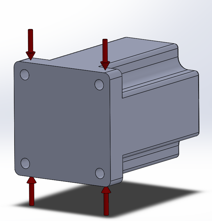
@Nxt-1, the downwards force would be from the motor's weight. Next time you pull one of the motors out, try to suspend it, with fingers at the arrow points shown below. But this is not a concern in your latest revision as the motor is supported at both ends. With this design, I would add a third damper mounting at the center position (between the two existing) on both, bottom and side mounting planes. This would give you some ability to experiment whereas maybe just one (centerline), or two (end-points), or all three dampers employed on the end/centerline would be best or for the bottom or side mount.
-
Over Friday and Saturday I designed, printed and tested some revisions and I don't think it's going to work out.
The first version looked very similar to the pictures I already posted here, but with just the front support (on the bottom and side). This was not really any better than the previous style brackets. The whole top bracket still resonated and noise was not really any better. During testing I also noticed I have made a minor error, resulting in a belt that was to right and pulling the motor to the side. It also seemed like the little rollers in the needle bearing were resonating.
To verify the bearing issue, I redesigned the bracket to accept 608 bearings instead. Testing showed no audible change in vibration levels. Test belt tension was also corrected, so the motor sits just about perfectly straight. While this version was printing I did design a version with 2 back support dampers, but ended up not printing it as it this style of bracket seems not they way to go and the motor sat level anyway.
To verify one more thing I removed the belt and did the same arc move that I have been using to test for a while now. And it was noticeably better. So what I feared seems true, the belt itself is poor vibration isolator. In fact the belt seems like the only real path the vibrations can couple into the rest of the machine.


-
At this moment I am debating whether to take the money dive and have the old style brackets cnc machined out of steel (weerg.com has a promotion that makes the steel options cheaper than alu at the moment
 )
)A user on the reprap forums reported that improved noise vibration issue he had with his nema23's (link to the post). It could make sense from a rigidity standpoint as well as the added mass, more mass is normally less vibrations right. Yet then again all the previous things I tried made sense too, and they didn't cost €360 to 'try out'.
-
@Nxt-1 if it is definitely the belt thats causing the resonance issues, I'd focus my efforts on that. Did you try the 20T pulleys? What about making a significant change to the belt length (longer or shorter)? Granted this might be tricky given the machine design... have you also tried using 9mm or 12mm belts instead? They'll at least have different mass/stiffness properties.