• Tags
  • Documentation
  • Order
  • Register
  • Login
Duet3D Logo Duet3D
  • Tags
  • Documentation
  • Order
  • Register
  • Login

duet 3 connecting z probe inductive sensor

Scheduled Pinned Locked Moved Solved
Duet Hardware and wiring
4
25
1.5k
Loading More Posts
  • Oldest to Newest
  • Newest to Oldest
  • Most Votes
Reply
  • Reply as topic
Log in to reply
This topic has been deleted. Only users with topic management privileges can see it.
  • undefined
    Phaedrux Moderator
    last edited by 3 Sept 2020, 22:24

    I suspect a bad signal wire from your probe.

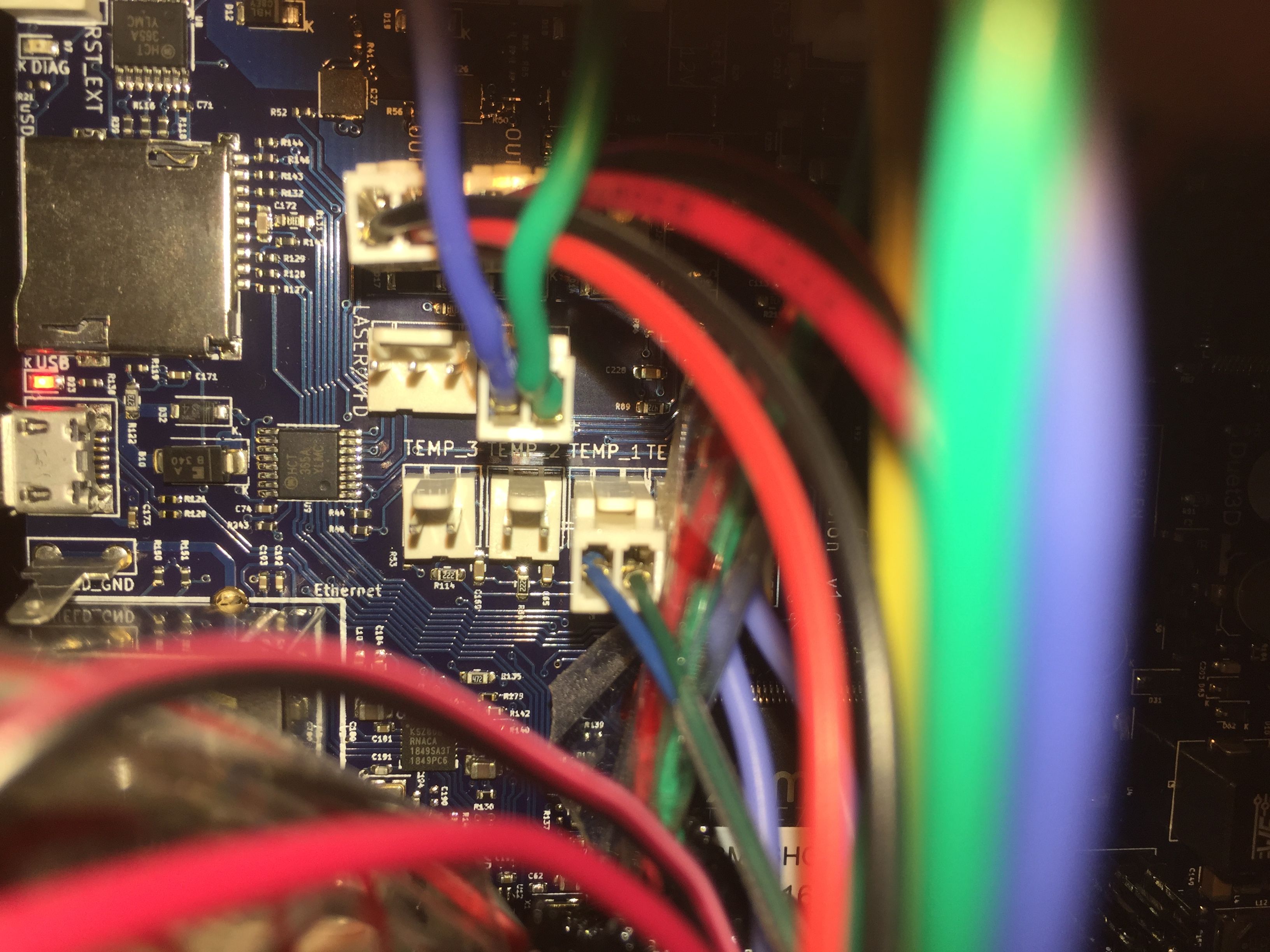
    In your photo, which wire is which?

    Z-Bot CoreXY Build | Thingiverse Profile

    1 Reply Last reply Reply Quote 0
    • undefined
      aprz
      last edited by aprz 9 Mar 2020, 22:55 3 Sept 2020, 22:44

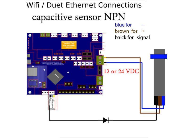
      the green (actually brown) is the positive, the black is the sensor, and the blue is negative. i may be wrong. reference diagram.
      ogA64gS3SXCmPhsQ.jpg

      1 Reply Last reply Reply Quote 0
      • undefined
        Phaedrux Moderator
        last edited by 3 Sept 2020, 23:15

        You have the brown/green wire connected to the 3.3v for power.

        The diagram shows the probe being connected to 12/24v vin.

        Does your probe function at 3.3v or does it need more?

        Z-Bot CoreXY Build | Thingiverse Profile

        undefined 1 Reply Last reply 4 Sept 2020, 03:05 Reply Quote 0
        • undefined
          aprz @Phaedrux
          last edited by 4 Sept 2020, 03:05

          @Phaedrux I just connected it to vin 24v but still see no difference in the z probe value.

          1 Reply Last reply Reply Quote 0
          • undefined
            Phaedrux Moderator
            last edited by 4 Sept 2020, 04:01

            Do you have a link to information on what probe it actually is?

            Z-Bot CoreXY Build | Thingiverse Profile

            undefined 1 Reply Last reply 4 Sept 2020, 04:31 Reply Quote 0
            • undefined
              aprz @Phaedrux
              last edited by aprz 9 Apr 2020, 04:34 4 Sept 2020, 04:31

              @Phaedrux This is the exact one. looks like the pnp style sensors require a resistor?

              https://www.amazon.com/Twidec-Inductive-Proximity-Detecting-LJ18A3-8-Z/dp/B07WS45K3P/ref=sr_1_1?dchild=1&keywords=b07ws45k3p&qid=1599193793&sr=8-1

              undefined 1 Reply Last reply 4 Sept 2020, 18:27 Reply Quote 0
              • undefined
                Veti
                last edited by Veti 9 Apr 2020, 04:41 4 Sept 2020, 04:40

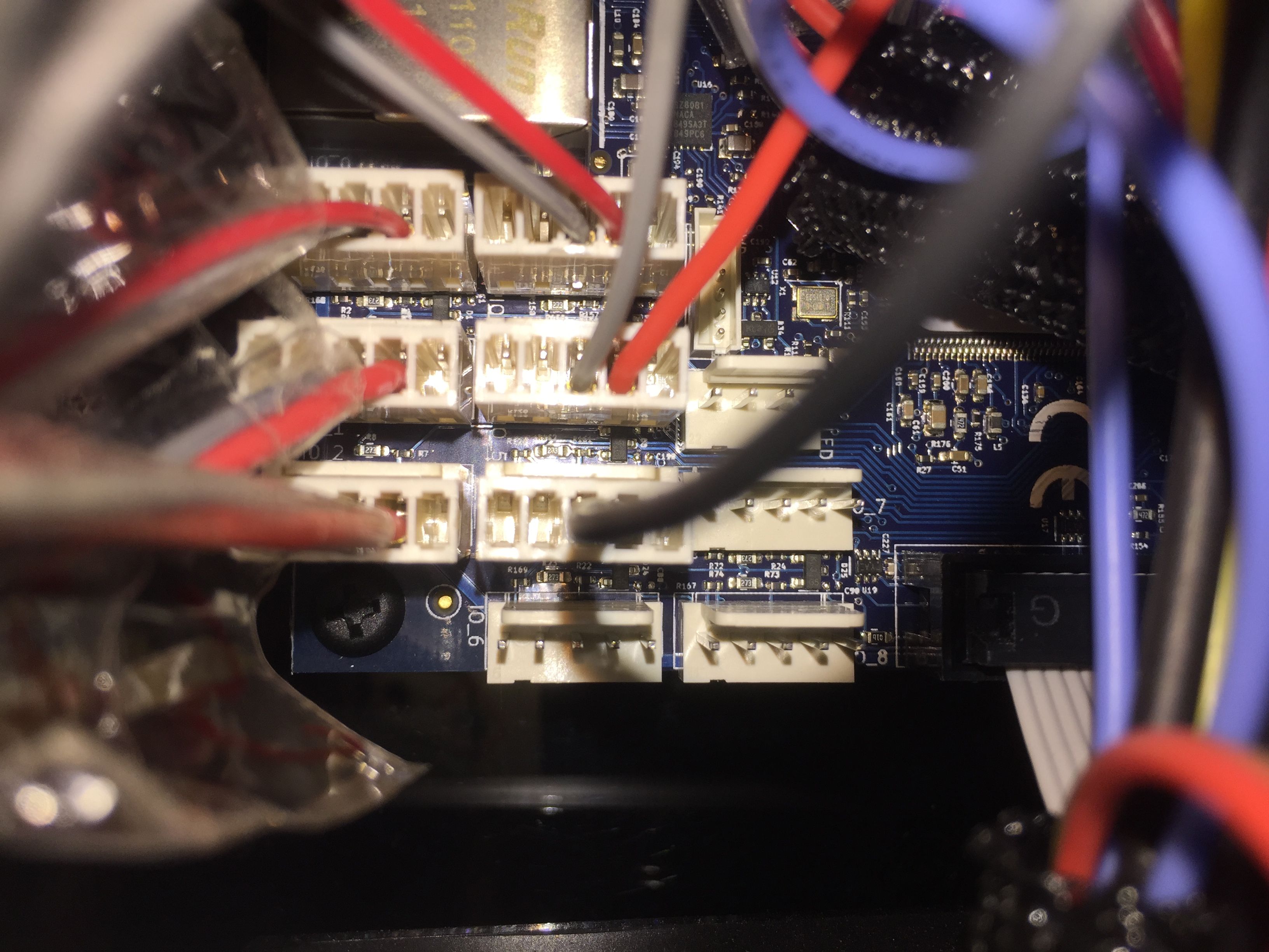
                can you show us your new wiring

                undefined 1 Reply Last reply 4 Sept 2020, 05:52 Reply Quote 0
                • undefined
                  aprz @Veti
                  last edited by aprz 9 Apr 2020, 05:53 4 Sept 2020, 05:52

                  @Veti Here it is. Picture 1 shows the signal wire connected to io5.in and picture 2 shows the positive and negative wires in 12v supply.

                  8F35663A-DB96-410E-AB41-A392A2A1ED8B.jpeg 9DEAE847-AC3A-45BA-BEFA-5D682EE716C3.jpeg

                  1 Reply Last reply Reply Quote 0
                  • undefined
                    Phaedrux Moderator @aprz
                    last edited by 4 Sept 2020, 18:27

                    @1997alex said in duet 3 connecting z probe inductive sensor:

                    @Phaedrux This is the exact one. looks like the pnp style sensors require a resistor?

                    https://www.amazon.com/Twidec-Inductive-Proximity-Detecting-LJ18A3-8-Z/dp/B07WS45K3P/ref=sr_1_1?dchild=1&keywords=b07ws45k3p&qid=1599193793&sr=8-1

                    Ok, so it's a PNP NO sensor not NPN.

                    https://duet3d.dozuki.com/Wiki/Connecting_a_Z_probe#Section_PNP_output_normally_open_inductive_or_capacitive_sensor

                    See if this makes a difference.

                    Z-Bot CoreXY Build | Thingiverse Profile

                    1 Reply Last reply Reply Quote 0
                    • undefined
                      aprz
                      last edited by aprz 9 Apr 2020, 21:07 4 Sept 2020, 21:04

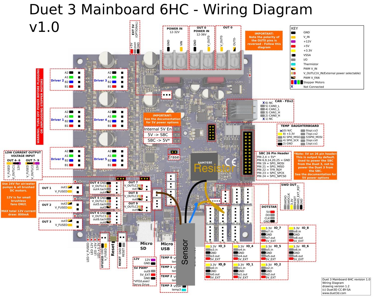
                      Ok,I ordered a few 10k, 30k and 68k resistors. I’ll follow up on how it comes out or whether it works. Here’s a drawing of how I’m understanding from the article how to connect the resistor to the duet and sensor. If this doesn’t work I’ll just buy a npn sensor. The yellow lines are the two resistors tied together and connected to ground and sensor wire.by the way the positive is going to be connected to 12v pin. Correct me if I’m wrong or a potential .
                      DE740FD6-62A9-42E7-ABA7-235AF5C10E5F.jpeg

                      1 Reply Last reply Reply Quote 0
                      • undefined
                        aprz
                        last edited by aprz 9 Oct 2020, 04:08 10 Sept 2020, 04:07

                        Ok never mind the resistors, I’ll try that out later but I just ordered another probe that is a npn swapped it out. It works just had to fix a couple wiring issues but anyone out there wanting to use a inductive sensor make sure it’s a npn inductive sensor, also the sensor works with the 3.3v power in the io5 pin and didn’t need to wire it to the vin or 12v. I have the brown going to 3.3v, the blue going to ground and the black going to “io5.in”. Well thanks for the help problem solved.👍

                        1 Reply Last reply Reply Quote 1
                        24 out of 25
                        • First post
                          24/25
                          Last post
                        Unless otherwise noted, all forum content is licensed under CC-BY-SA