More CureXYUVAB motion planning tricks
-
Love following this!
The preprocessing Python script is a great idea. Have you considered implementing some sort of sliding window average, rather than a binary decision tree? I guess it’s complicated in that you’d need to estimate your time axis as well.
-
@whopping-pochard Thanks but you over estimate my coding and maths capabilities. I can just about hack something together to do basic stuff with the aid of the internet and a search engine, but I'm not good at this sort of thing (and I'm getting too old to learn).
Actually it's the firmware that does all the clever stuff. All I do is supply absolute position commands via gcode for the 3 gantries, and the firmware takes care of working out the moves required to match those positional coordinates, and generating the step pulses to keep all those moves in sync so that they start and end at the same moment in time. Which is clever stuff when one considers that different gantries move different distances within the same time frame. -
@deckingman said in More CureXYUVAB motion planning tricks:
I can just about hack something together to do basic stuff with the aid of the internet and a search engine
I know some people who built their software engineering career on this method (-;
-
cool writeup, dunno why I assumed that that whole UVAB part was somehow automagically handled by the RRF

btw, what slicer is generating ARC moves for you?
-
@arhi said in More CureXYUVAB motion planning tricks:
cool writeup, dunno why I assumed that that whole UVAB part was somehow automagically handled by the RRF
Nah - only if you map the U and A motors to the X axis and the V and B motors to the Y axis after homing. Then the firmware "thinks" it has 3 X motors and 3 Y motors and gives them the same step pulses (which is how I used to run it.
btw, what slicer is generating ARC moves for you?
I use Slic3R in it's various guises (including PE versions), and before you say it - yes the process would be a lot easier if I started out with G2 and G3 controlled arc moves.
-
@deckingman said in More CureXYUVAB motion planning tricks:
which is how I used to run it.
clear now, but it kinda makes sense for firmware to support such thing.. on the other hand, it makes sense for slicer to support it too .. I'm looking at the arm that moves extruder up/down on the delta's .. this is in some way similar
btw, what slicer is generating ARC moves for you?
I use Slic3R in it's various guises (including PE versions), and before you say it - yes the process would be a lot easier if I started out with G2 and G3 controlled arc moves.
iirc none of the slic3r forks know how to output g2 and g3?
the arc part is unclear.. you are trying to detect arc from a block of g1 moves or?have you seen the work done to match arcs to existing g-code?
https://github.com/FormerLurker/ArcWelderPlugin/dunno if that would help, have not looked at the source myself
-
@arhi said in More CureXYUVAB motion planning tricks:
iirc none of the slic3r forks know how to output g2 and g3?
the arc part is unclear.. you are trying to detect arc from a block of g1 moves or?Yes - but not necessarily just arcs. It's conceivable that the gcode for something like say a miniature model, could consist of a series of small XY moves. So I define a small "feature" as being a block of consecutive moves which are smaller than a certain length. In my case, I use 1.6mm because that works well with the gcode that Slic3R produces. As it happens, something like a hole in a part would be made up of a curve which was made from small segmented moves. So if it's diameter is less than my "Y" tolerance of 30mm then the extruders get parked in the centre of that "feature" and don't have to replicate those small XY moves. But the code would work on any small feature, whatever shape it happened to be, as long as it was made up of a block of small moves and had dimensions of less than 40mm in X and 30mm in Y.
In summary, that section of code will "park" the extruder gantry in the centre of any small features (as defined above), whether that feature happened to be a circular hole, an eclipse, a rectangle, or even a non-geometric shape.have you seen the work done to match arcs to existing g-code?
https://github.com/FormerLurker/ArcWelderPlugin/dunno if that would help, have not looked at the source myself
Haha - sorry but that made me chuckle. It's our crazy English language again.
") . The word "arc" has 2 meanings. The first one refers to a part of a curve. The second meaning of "arc" is an electrical discharge between two electrodes. So "arc welding" is a process that is used to join metal by using an electric "arc" to create enough heat to melt it - nothing to do with motion.
. The word "arc" has 2 meanings. The first one refers to a part of a curve. The second meaning of "arc" is an electrical discharge between two electrodes. So "arc welding" is a process that is used to join metal by using an electric "arc" to create enough heat to melt it - nothing to do with motion. -
@deckingman said in More CureXYUVAB motion planning tricks:
In summary, that section of code will "park" the extruder gantry in the centre of any small features (as defined above), whether that feature happened to be a circular hole, an eclipse, a rectangle, or even a non-geometric shape.
All clear, it's just that choice of words led me to believe you are using slicer that actually generate G2/G3 'cause I undestood something along the line "arc move can get the hotend to a position futher from extruder than allowed" .. if we are looking at linear move looking at start and end point is pretty straight forward so I assume G2/G3 that would maybe along the line, go out of the way
I have not tried it myself but KISS slicer supposedly knows how to generate G2/G3
have you seen the work done to match arcs to existing g-code?
https://github.com/FormerLurker/ArcWelderPlugin/dunno if that would help, have not looked at the source myself
Haha - sorry but that made me chuckle. It's our crazy English language again.
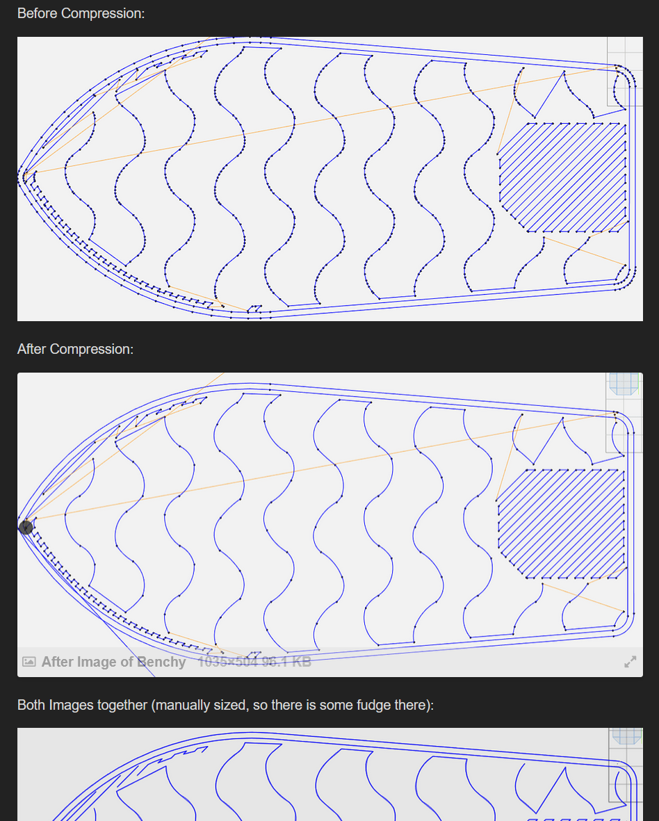
. The word "arc" has 2 meanings. The first one refers to a part of a curve. The second meaning of "arc" is an electrical discharge between two electrodes. So "arc welding" is a process that is used to join metal by using an electric "arc" to create enough heat to melt it - nothing to do with motion.That play of words is why FL named it "Arc Welder". What that plugin does is it replaces a bunch of G1 moves with a smaller number of G2/G3 moves matching arc on top of the existing linear move.
you can see how the development went and a long discussion about it on octoprint forum: https://community.octoprint.org/t/new-plugin-anti-stutter-need-testers/18077
e.g.
Dunno if this type of analysis of G-Code and modification could be used to make better UVAB moves or not but it's good to know it exists ... what comes to mind for e.g. is that every time ARC is recognised, if radius is less than acceptable missalignment of XY and UV you position UV at the center .. or something similar ..
-
@arhi Ahh OK - my bad. I didn't get any further than the word "arc welder" and jumped to the wrong conclusion - I'll take a look when I get time....
-
@arhi Actually my explanation of how the code detects small features has triggered a thought process. In a gcode file, any "feature" consists of block of G1 Xnn Ynn Enn moves delimited by one or more commands without any "E" value, such as an XY only move, a feedrate change, or a retraction. So I could detect "small features" simply by finding the minimum and maximum X and Y values for those blocks of G1 Xnn Ynn Enn, and generating UV moves to "park" the extruder gantry in the centre of those features. That would catch any small features regardless of the length of any moves within those small features, rather than only detecting small features which are entirely made up of small moves.
-
@deckingman yes, that sounds like what you are doing / trying to achieve. IMHO better approach would be some "elastic link" between hotend and extruder but the implementation of that is not nearly as simple. Question is would the system benefit from that and how much.
The approach you are using now is how I'd do the first proof of concept too. After that works I'd try the second system to see if I can improve, but, it's not a small task and I'd do it only if I'm not satisfied with the original solution. The way to implement the "elastic link" I'd probably tackle by internally simulating the movements and calculating the new g-code from it but that's just first idea I have, did not think about it too much
.. maybe I'd try to implement a new movement system in the RRF itself to make firmware handle that (and fail most probably ) -
@arhi said in More CureXYUVAB motion planning tricks:
........................IMHO better approach would be some "elastic link" between hotend and extruder but the implementation of that is not nearly as simple. Question is would the system benefit from that and how much.
Funnily enough, I had a mechanical version of that before I fitted motors to the extruder gantry - although the cords connecting the hot end to the extruder gantry weren't very elastic. It worked well for the short zigzag infill moves but didn't work well with longer moves, because with the extruder gantry being so heavy, it had a tendency to overshoot. It takes a quit a tug to get 3Kgs moving but once it is moving, it doesn't want to stop
.......maybe I'd try to implement a new movement system in the RRF itself to make firmware handle that (and fail most probably
)With my very limited coding skill, that's not something I would never attempt. I would imagine the difficulty would be that one would need to somehow look ahead because it is necessary to anticipate what the XY gantry is going to do next in order to calculate the optimum UV position, rather than work on what the XY axes have already done or are doing right now. That's a bit like one of my other Python scripts which moves the tool change point ahead in the gcode file, so that much of the purge happens while it is still printing with the "old" filament.
-
@deckingman said in More CureXYUVAB motion planning tricks:
I would imagine the difficulty
As I said I'd probbly fail myself trying to do that
Anyhow looking the video how it works now I don't see much point in spending time improving it, it works awesome from what I see
-
@arhi said in More CureXYUVAB motion planning tricks:
Anyhow looking the video how it works now I don't see much point in spending time improving it, it works awesome from what I see
Yes, I think it's pretty much there. For the larger cylinders where the extruders follow the hot end, I thought about having the extruders do smaller circle. So for example if the cylinder was say 100mm diameter, the extruders could do a 70mm diameter circle, but I don't see what advantage that would give me.
I'll think I'll leave it as is for now and get back to trying to get a 6 input hot end to actually mix filaments
I have a liquid cooling solution designed - now all I have to do is make it. .