Duet 2 Ethernet and SBC
-
@smoki3 said in Duet 2 Ethernet and SBC:
I tried
did you try without the duex? i realize you probably need the duex, but if nothing else it could help narrow down what to focus on
-
@bearer said in Duet 2 Ethernet and SBC:
@smoki3 said in Duet 2 Ethernet and SBC:
I tried
did you try without the duex? i realize you probably need the duex, but if nothing else it could help narrow down what to focus on
Not as easy. Then I have to wire my complete printer again
-
If I could load and simulate with your config shouldn't you be able to just disconnect the 50 pin ribbon and power and run a simulation as well?
-
@bearer then I already get a lot of errors while booting, because the drivers are missing
-
@smoki3 Don't worry about your wiring. It most likely is a firmware issue. Unfortunately I did not have any time since the last time I wrote here to look into that.
Manuel
Duet 3 6HC (v0.6) with RPi 4B on a custom Cartesian
with probably always latest firmware/DWC (incl. betas or self-compiled)
My Tool Collection -
So when this works for the Ethernet model would it be possible to run spaghetti detective?
Also, for the D2E, would this offloading to the SBC enable smoother segments on Delta's using mesh compensation?
-
@Baenwort said in Duet 2 Ethernet and SBC:
possible to run spaghetti detective?
Presumably you'd need to pause the Duet either by triggering on a input pin or sending g-code to pause - as such how the SBC is connected doesn't really matter much except you can use
echo M25 | sudo CodeConsolerather than saycurl ..blah blah..orecho M25 > /dev/ttyAMC0which might require a little setup and flushing of the usb serial first?
As for smoother I can't say I'm authority on it, but unless the bottleneck was reading g-code from the SD card moving to a SBC isn't going to improve the handling as the realtime motion planning from the g-code is still done on the Duet.
-
@bearer the spaghetti detective bit was because with a SBC to act as the plugin host it would be potentially easier to port the octoprint plugin.
The comment about smoothness is because I was told once that because of the complexity of the Delta math that on Duet 2 if you enabled mesh bed compensation that it no longer calculated every point to move but fell back on arcs and segments like ordinary RAMPS. But if a SBC offloads some work from the duet I wondered if more could be calculated with the now freed up resources.
It presumes that the DWC takes up some amount of resources to run on the Duet processor.
-
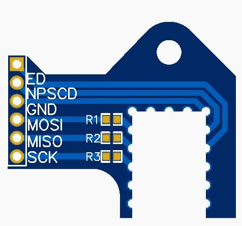
OK, here's my thinking on an easy way to connect SBC regardless of ethernet or wifi version.
The header on the side is a 2.54mm, could accept female or male, protrudes past the board edge and sits forward and next to the paneldue header. The adapter is soldered to the bottom in the same manner the ESP is attached to the top. It could also be mounted with pins through it.
Hole for plastic push-fitting to reinforce.
Relief is left for up to a 7mm diameter fastening post around the board mounting screw. Resistors are 470-Ohm.
Anything I am missing?
-
@deadwood83 said in Duet 2 Ethernet and SBC:
Anything I am missing?
maybe some pull downs to the reset/enable lines to ensure no interference (unless rff 3.2 handles that in firmware) could be jumpered for flexibility i guess.
-
@bearer I think it would be much less intrusive to figure out a way to pull PE4 and PE5 low in firmware.
I poked around in the Duet3 designs and I see that someone (Tony?) had a great idea for v1.1.
Input buffers. With that in mind, I present version two! All parts available for SMT from JLC, incorporates the design guidelines laid out in the duet3, comes to $19.5USD per 10 (please note I am not selling these, this is the price from JLCPCB) (plus shipping). Sadly I did have to bump it to a dual layer PCB.
For V1.04 Duet Wifi, the CS/NPCS0 pin already has a 2k2 resistor. R2 can be bridged in that case.
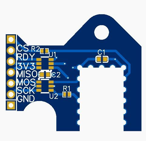
Fixed the dims.
-
@deadwood83 why solder to board instead plugin in to the header?
-
@arhi said in Duet 2 Ethernet and SBC:
@deadwood83 why solder to board instead plugin in to the header?
presumably because wifi boards don't have headers?
-
@bearer wifi boards you have to desolder the board right? so if you do that you can solder on the 2 headers thats easier than removing the esp module
 ...
... -
@arhi said in Duet 2 Ethernet and SBC:
@bearer wifi boards you have to desolder the board right?
simply disabling it in either RRF or WiFi firmware seems to work, but can't say I've done a ton of testing (there is a thread with a pogo pin thing to slap on top of existing wifi module and worked for the limited testing i did)
-
@bearer ah, that's cool then
") ... I dislike wifi in general so never even tried the duet2wifi board all my duet's are eth ... anyhow it's rather easy to solder a header on this board too so not a biggy even as is it is very useful
... I dislike wifi in general so never even tried the duet2wifi board all my duet's are eth ... anyhow it's rather easy to solder a header on this board too so not a biggy even as is it is very useful -
@arhi said in Duet 2 Ethernet and SBC:
anyhow it's rather easy to solder a header on this board too so not a biggy even as is it is very useful
true, but the headers holes are covered by the wifi module which is probably not for everyone to remove.
-
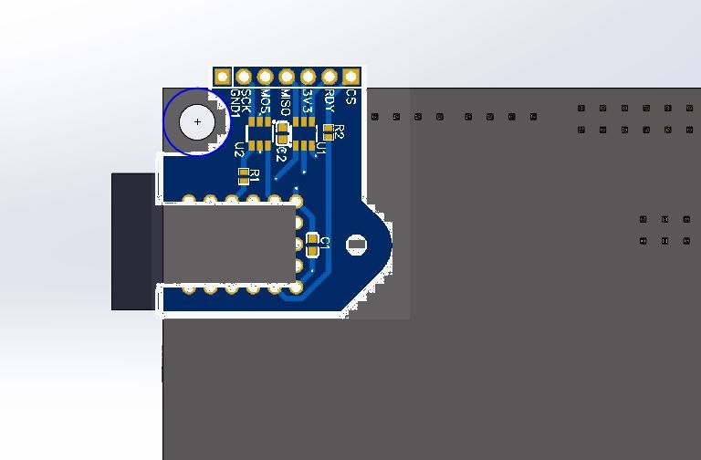
It is version agnostic. It is attached to the back of the board, so it works with both ethernet and wifi versions. No desoldering required, only attaching pins to the Pi header. I will publish the public EasyEDA links once I verify all my measurements in KiCad.
EDIT:
-Updated image to be proper scaling.
-Created non-hollow version with plated through-holes for ethernet users who want to stick it on the headers
-License is CERN open hardware, feel free to commercialize it if anybody feels so motivated.
-Strengthened top section, re-scaled text, verified clearance against paneldue header, extended bottom of board to index against duet mainboard.
-NO DESOLDERING NECESSARY
-Updated grounding to star/bus ground patternI took the plunge.
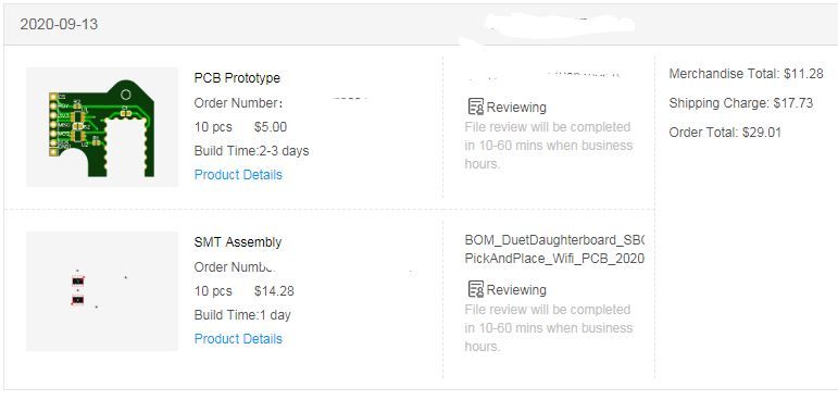
I will keep 5 for me. The others can go to homes in the US at the cost of a flat rate envelope.
-
I think I may have messed up in my design.
@T3P3Tony I have a question about the SBC conn on the duet 3 v1.01. On my little breakout I put a 470-Ohm in series with the input buffers on SCLK and only just realized (after ordering some) that your placement of the 470 was NOT on the clock line but rather on PC23/IO_7_OUT. Looking at TI's guidelines for matching a series damping resistor: https://www.ti.com/lit/an/scba012a/scba012a.pdf
Assuming worst-case scenario, at max output current for the SN74LVG2G34 (12mA) we get Irms of ~8mA
Using PCBWay's trace impedance tool shows a line impedance of roughly 105-Ohm for 2 layer FR4 1.6mm 1-Oz copper PCB using the trace width of .61mm
My worry is that the 470-Ohm resistor will provide too much dampening and round off the waveform peaks too much since SCK on the daughterboard lives at the termination rather than origination (or could this be considered the origination due to the amount of PCB the signal must travel?). Do you think this is a valid worry, or should it be OK with the resistor there at the current speed of 8MHz?
Considering other solutions to this point involved some wires with crimped/socketed resistors, and one instance of a breadboard, am I just overthinking it now?
-
@deadwood83 said in Duet 2 Ethernet and SBC:
The schematics/PCB
awesome
thanks
Did you made this in kicad and exported to easyeda or you made it directly in easyeda. I can redraw it in kicad but if you already have it in kicad it would save me some time