Duet3D Logo Duet3D
    • Tags
    • Documentation
    • Order
    • Register
    • Login
    1. Home
    2. deadwood83
    • Profile
    • Following 0
    • Followers 3
    • Topics 4
    • Posts 26
    • Best 7
    • Controversial 0
    • Groups 0

    deadwood83

    @deadwood83

    11
    Reputation
    26
    Profile views
    26
    Posts
    3
    Followers
    0
    Following
    Joined Last Online

    deadwood83 Unfollow Follow

    Best posts made by deadwood83

    • RE: 3D printing is killing our Privacy!!11!

      The experts do not believe self-regulation would be sufficient without oversight. The new regulatory body could be organized by existing licensing organizations such as the UK Copyright Hub, National Copyright Administration of China, the UK Intellectual Property Office, the Copyright Tribunal, or Information Commissioners Office.

      Dr. Griffin said: "Digital watermarking and 3-D printed products present a future where objects can be searched for with nothing more than the equivalent of a Google search word. 3-D printing and digital watermarking specifically has not been considered by any government or regulatory body, nor has there been any regulatory research carried out on the matter. Our proposals help to ensure the protection of individual privacy in an increasingly digitized world."

      "Oh noes! Someone's gonna print my thing and I'm not gonna get paid for it!"

      The only other thing I can imagine from that article, which had quite a few glaring typos such as:

      Legally governing 3-D printing is not straightforward as the underlying technologies are so precise. With 4-D printing objects print themselves and the use of augmented and virtual reality allows for enhanced tracking.

      What? So someone in biomed 3d prints me some new arteries for some reason and they get installed. They propose all the tracking with copyright orgs so that the design of my arteries is protected?

      Lol no. They want to have a formal way to sue the pants off amateur CAD designers for infringing copyright / patents whether intentionally or not.

      . . . a new voluntary code of conduct to protect people's privacy, and a regulatory body to provide guidance and oversight.

      Oh yeah, a regulatory body to just provide guidance and oversight. Right up until the lobbyists walk into parliament offices / congress. The pandering is not subtle.

      Not sure if this paper is "I need to keep my tenure" or "please hire me away from this University"

      Some more goodies:

      . . . to trace, track and observe objects, which can reveal an incredible amount of information about the users of such content."

      Oh yeah, good point. Like being seen using an Adroid phone? Or wearing Airpods? Or the carrier branding on your phone's exterior? How about the information your personal transport provides about you? Brand names on clothes? What about the home you live in?

      The experts carried out 30 in-depth interviews with representatives from Chinese 3-D printing companies.

      Mmhm. Best to consult the experts when it comes to privacy issues / tracking / intellectual property rights.

      The article is kind of gross. The linked article gives it all away:

      Academics will analyse what the impact of this system would be on copyright law. Credit: Shutterstock

      So this article is a remix of another article which is itself a follow-up to a third article. That's quality content right there.
      posted in 3D Printing General Chat
      deadwood83undefined
      deadwood83
    • RE: Duet 2 Ethernet and SBC

      @smoki3 it would still require traces back to the 24v input. Also, the coils used on those (and more often the B or C-lot mp1584) are intolerant of feedback on the 12/24v line. Not to mention the RF noise it generates and the extra heat to dissipate. When the fail, they fail open. If that overwhelmed the 3.3v stepdown on the pi it would probably damage the input buffers on the PCB; so then you're either doing micro soldering or putting on a whole new daughterboard just to avoid running one tap from the PSU and a dedicated 5V for the pi.. in addition to having to buy a new pi.

      Add that to quadrupling the PCB cost due to needing to stretch all the way back to the inputs and suddenly that mod costs Pi+PCB+Time+Risk to damaging mainboard. Add a voltage regulator after the input and the PCB SMT cost skyrockets due to small quantity. It's just not worth it and defeats the tiny form factor. One of my goals was to give people an option to add SBC support without having to redesign mainboard housings.

      In comparison, a 50W Meanwell 5V supply is ~USD $13 and includes a meshed RF-blocking shell (for the high frequencies that could interfere with comms); voltage regulation; transient handling; and is not exposed to feedback spikes from, say, a ceramic-potted heater cartridge.

      The design is fully open source. I won't ever put a cheap digital buck, but nothing stopping you from dipping a toe into PCB creation and doing it yourself. That's how I got started, and I highly recommend it. It's pretty fun!

      My 5v PSU and USB-C hookup should be here Wednesday. Kudos to the firmware team for the excellent work on the Duet2 SBC support. I have not been able to derive a synthetic test which causes it to fail where standalone does not. I still have 4 PCBs I am willing to send at the cost of postage to homes in the continental USA.

      posted in Beta Firmware
      deadwood83undefined
      deadwood83
    • RE: Firmware Retraction causing odd pauses

      You're a wizard. That solved everything. It is now flying as I would expect it to!

      Thank you so much for the second set of eyes.

      posted in Tuning and tweaking
      deadwood83undefined
      deadwood83
    • RE: Can Duet3D boards drive Cool Muscle closed-loop motors?

      That right there is an Azteeg X3 Pro. https://www.panucatt.com/Azteeg_X3_Pro_p/ax3pro.htm

      Specifically, it is a clone of an Azteeg X3 Pro. The genuine boards have screw terminals where the clones have Molex 4-pin headers.

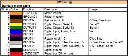
      coolmuscleCM1.JPG

      As others said, the expansion board should work but it is difficult to say what sort of cost/benefit ratio you would be looking at versus getting a replacement Azteeg and trying to figure out the firmware.

      posted in Duet Hardware and wiring
      deadwood83undefined
      deadwood83
    • RE: Duet 2 Ethernet and SBC

      @bearer I think it would be much less intrusive to figure out a way to pull PE4 and PE5 low in firmware.

      I poked around in the Duet3 designs and I see that someone (Tony?) had a great idea for v1.1.

      Input buffers. With that in mind, I present version two! All parts available for SMT from JLC, incorporates the design guidelines laid out in the duet3, comes to $19.5USD per 10 (please note I am not selling these, this is the price from JLCPCB) (plus shipping). Sadly I did have to bump it to a dual layer PCB.

      For V1.04 Duet Wifi, the CS/NPCS0 pin already has a 2k2 resistor. R2 can be bridged in that case.SBCAdapterv2.JPG

      Fixed the dims.

      posted in Beta Firmware
      deadwood83undefined
      deadwood83
    • RE: Duet 2 Ethernet and SBC

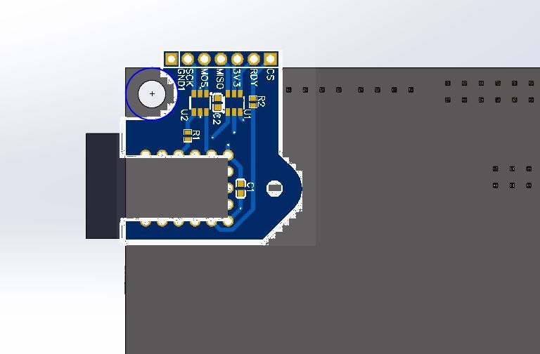
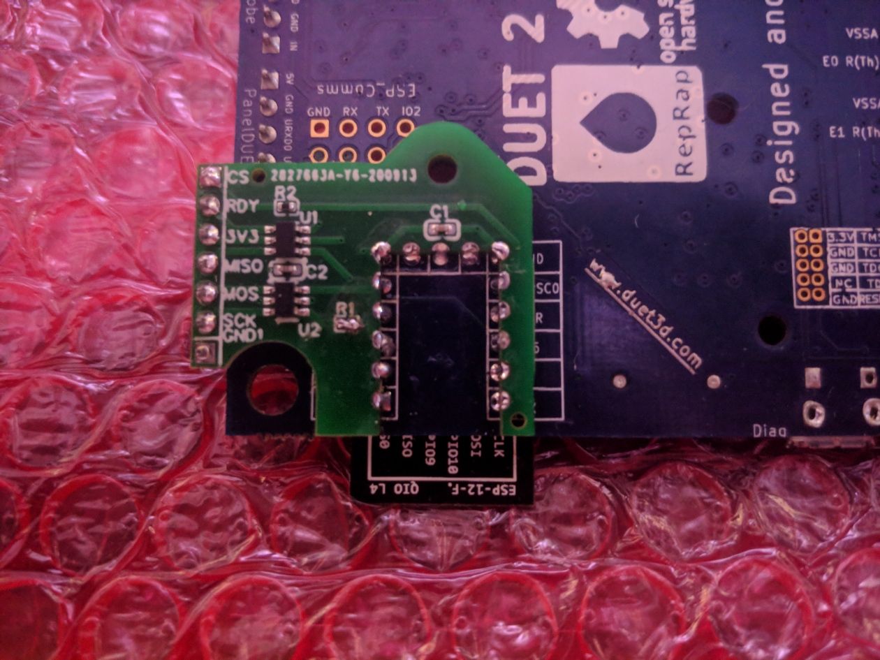
      It is version agnostic. It is attached to the back of the board, so it works with both ethernet and wifi versions. No desoldering required, only attaching pins to the Pi header. I will publish the public EasyEDA links once I verify all my measurements in KiCad.duetFit.JPG

      EDIT:
      -Updated image to be proper scaling.
      -Created non-hollow version with plated through-holes for ethernet users who want to stick it on the headers
      -License is CERN open hardware, feel free to commercialize it if anybody feels so motivated.
      -Strengthened top section, re-scaled text, verified clearance against paneldue header, extended bottom of board to index against duet mainboard.
      -NO DESOLDERING NECESSARY
      -Updated grounding to star/bus ground pattern

      The schematics/PCB

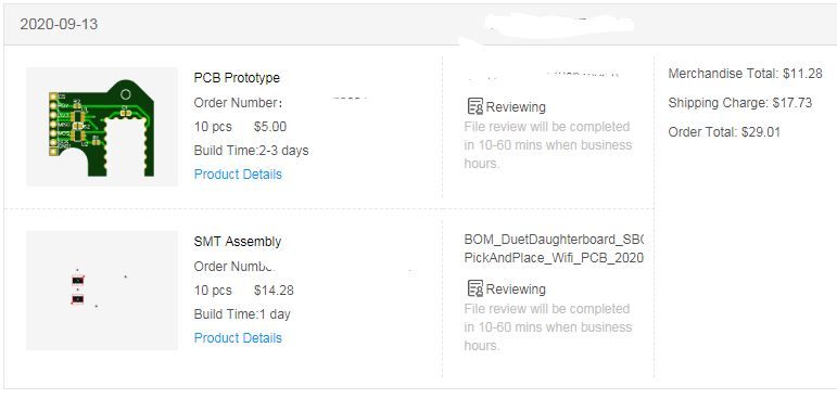
      I took the plunge. JLC.JPG

      I will keep 5 for me. The others can go to homes in the US at the cost of a flat rate envelope.

      posted in Beta Firmware
      deadwood83undefined
      deadwood83
    • RE: Duet 2 Ethernet and SBC

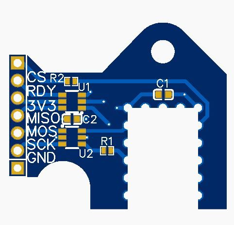
      OK, here's my thinking on an easy way to connect SBC regardless of ethernet or wifi version.

      The header on the side is a 2.54mm, could accept female or male, protrudes past the board edge and sits forward and next to the paneldue header. The adapter is soldered to the bottom in the same manner the ESP is attached to the top. It could also be mounted with pins through it.

      Hole for plastic push-fitting to reinforce.

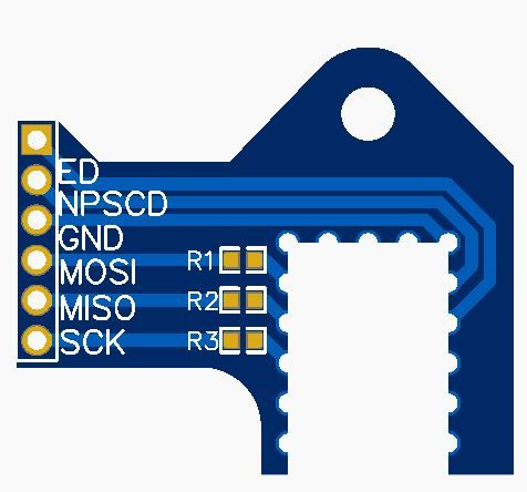
      Relief is left for up to a 7mm diameter fastening post around the board mounting screw. Resistors are 470-Ohm.

      Anything I am missing?
      SBCAdapter.JPG

      posted in Beta Firmware
      deadwood83undefined
      deadwood83

    Latest posts made by deadwood83

    • RE: Duet maximum achievable step rates

      Might be a bit presumptive to ask since I do not know the heart of DSF very well, but would these rates conceivably be different with an SBC at a future date?

      I.e. is computational offload to SBC present/planned or will it remain as an alternative method of getting gcode to the board? Asking on behalf of my ~620step/mm extruder (duet 2).

      Also, good information though maybe on the high side? my duet2 cannot run a btech bmg at 417.29 steps/mm at 128 microstepping with 30mm/s retracts without accruing ~600 hiccups over a 2 hour print.

      Either way, this is some super good baseline information. Thanks.

      posted in Duet Hardware and wiring
      deadwood83undefined
      deadwood83
    • RE: Duet 2 Ethernet and SBC

      @smoki3 it would still require traces back to the 24v input. Also, the coils used on those (and more often the B or C-lot mp1584) are intolerant of feedback on the 12/24v line. Not to mention the RF noise it generates and the extra heat to dissipate. When the fail, they fail open. If that overwhelmed the 3.3v stepdown on the pi it would probably damage the input buffers on the PCB; so then you're either doing micro soldering or putting on a whole new daughterboard just to avoid running one tap from the PSU and a dedicated 5V for the pi.. in addition to having to buy a new pi.

      Add that to quadrupling the PCB cost due to needing to stretch all the way back to the inputs and suddenly that mod costs Pi+PCB+Time+Risk to damaging mainboard. Add a voltage regulator after the input and the PCB SMT cost skyrockets due to small quantity. It's just not worth it and defeats the tiny form factor. One of my goals was to give people an option to add SBC support without having to redesign mainboard housings.

      In comparison, a 50W Meanwell 5V supply is ~USD $13 and includes a meshed RF-blocking shell (for the high frequencies that could interfere with comms); voltage regulation; transient handling; and is not exposed to feedback spikes from, say, a ceramic-potted heater cartridge.

      The design is fully open source. I won't ever put a cheap digital buck, but nothing stopping you from dipping a toe into PCB creation and doing it yourself. That's how I got started, and I highly recommend it. It's pretty fun!

      My 5v PSU and USB-C hookup should be here Wednesday. Kudos to the firmware team for the excellent work on the Duet2 SBC support. I have not been able to derive a synthetic test which causes it to fail where standalone does not. I still have 4 PCBs I am willing to send at the cost of postage to homes in the continental USA.

      posted in Beta Firmware
      deadwood83undefined
      deadwood83
    • RE: Duet 2 Ethernet and SBC

      Dry run looks super promising. I goofed though and realized I do not have any 24->5V USB-C power delivery units.

      Duet2SBC_DryRUN1.JPG
      Duet2SBC_DryRUN2.JPG
      IMG_20200925_121720.jpg

      Now I need to build out a male-male harness, throw this on my delta, solder a second board to the delta duet, and try a real run.

      posted in Beta Firmware
      deadwood83undefined
      deadwood83
    • RE: Duet 2 Ethernet and SBC

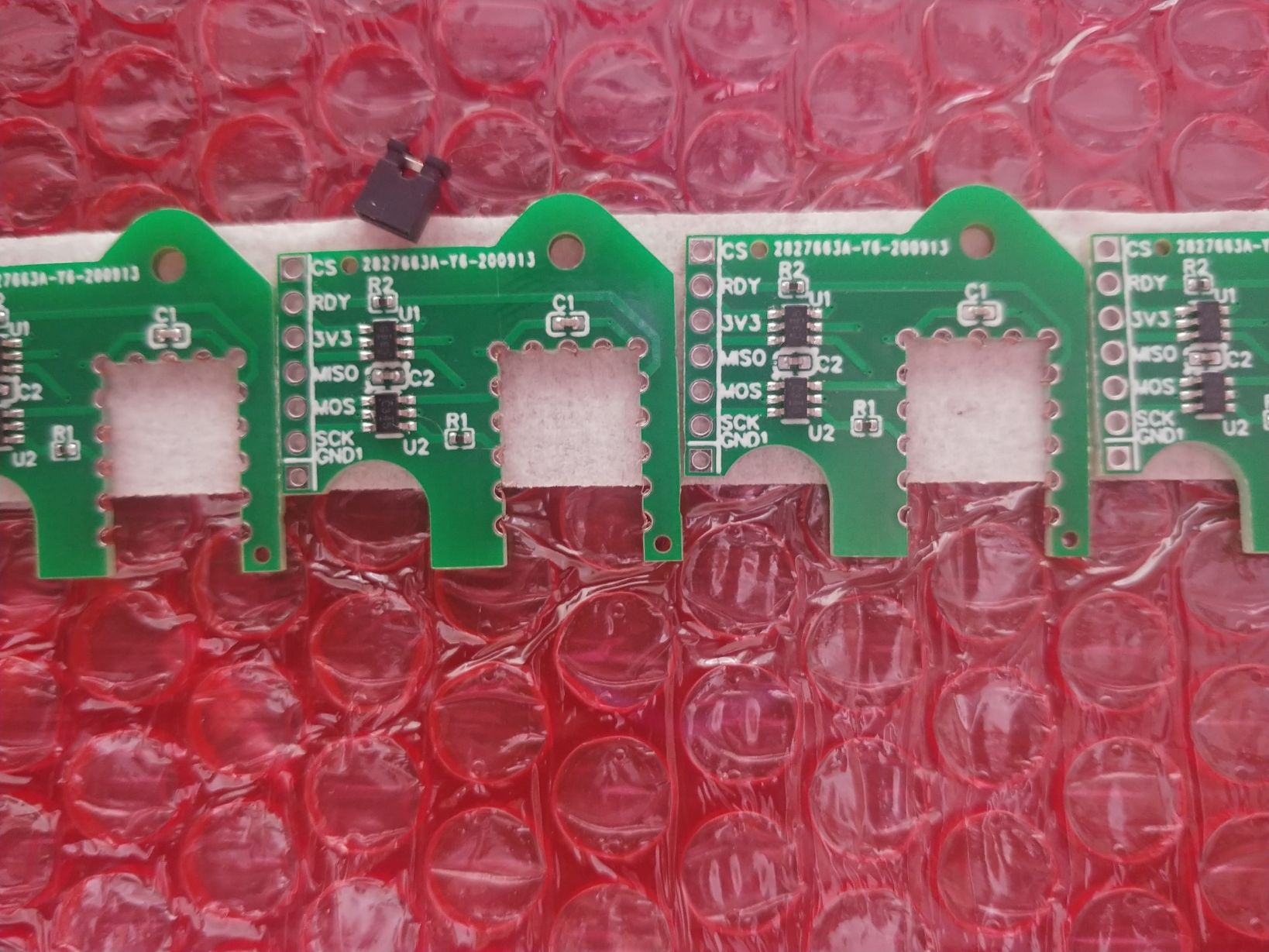
      Have you ever had a DHL driver scream at you then throw a package at your face while shouting "Social distancing?"

      Yeah, me either. They do leave things at my door and run away though. Jumper for scale.20200925_091645.jpg

      Look at those tiny resistors. Aren't they cute? you could accidentally desolder them with an intense gaze. I'm going to do just that to R1 and at least once to an R2.

      posted in Beta Firmware
      deadwood83undefined
      deadwood83
    • RE: Diagnosing a failing ESP-12

      It's ALIIIIIVE!

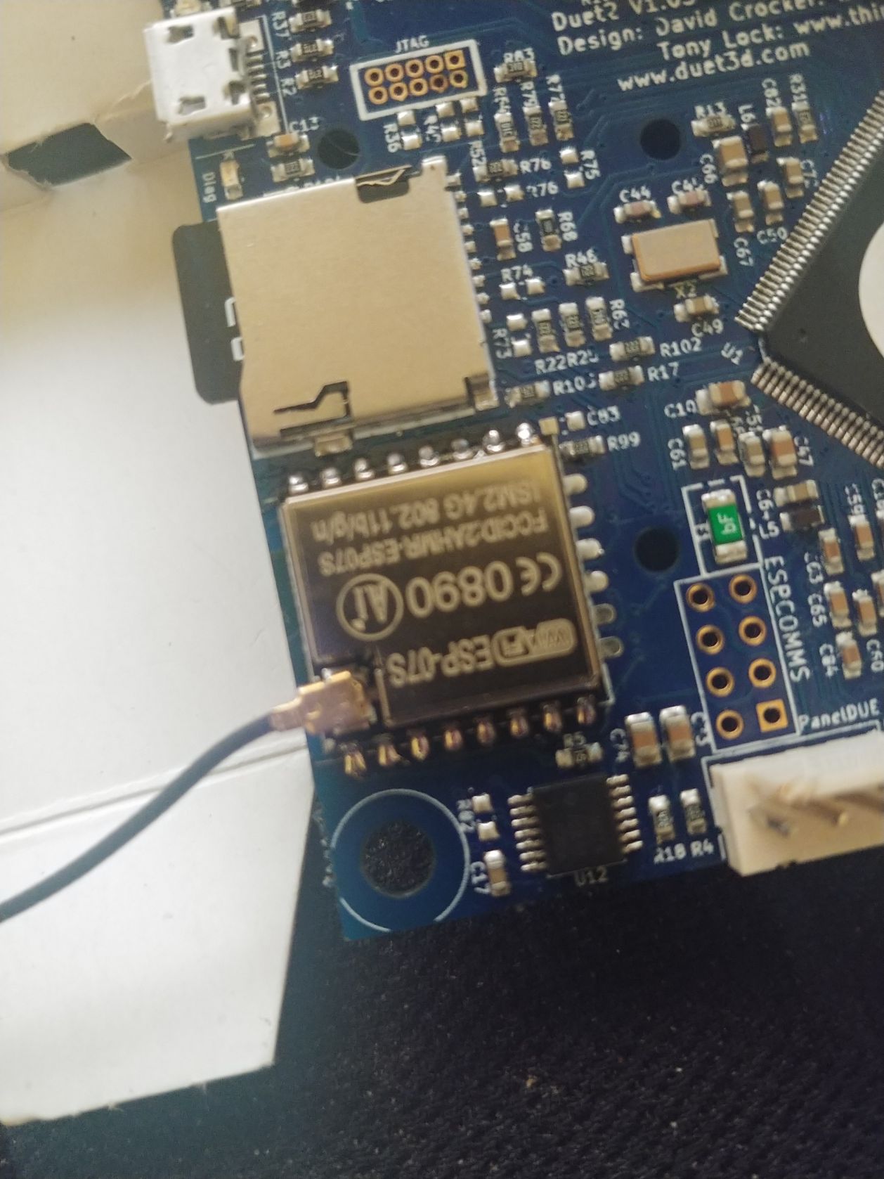
      It was the ESP all along. One of the diodes (too small to see?) along the edge with GND and CS had fractured solder.

      Guess I could have baked it, but honestly not worth the effort when an ESP-07s is available.

      20200916_200820.jpg

      I think I now have the confidence to try replacing the E1 driver on my 1.02 board if I ever take it out of the DLP printer.

      posted in Duet Hardware and wiring
      deadwood83undefined
      deadwood83
    • RE: Is the PanelDue display my only option?

      @GeorgeM You 100% need an M575 in the config and you need to set the baud on the BTT panel to 57600

      source: running a TFT35V2 on one of my Duets

      posted in General Discussion
      deadwood83undefined
      deadwood83
    • RE: Duet 2 Ethernet and SBC

      @arhi

      There is a PCB in the EasyEDA link which is closed off and with through-holes for the ethernet board for those who want to just stick on some headers and go. The components are low-profile so it will fit top or bottom.

      The only things you would need to add are 5v buck and some LEDs. Look in the EasyEDA project for ethernetPCB and you will find it there, ready for you.👍

      posted in Beta Firmware
      deadwood83undefined
      deadwood83
    • RE: Duet 2 Ethernet and SBC

      @arhi said in Duet 2 Ethernet and SBC:

      @deadwood83 said in Duet 2 Ethernet and SBC:

      The schematics/PCB

      awesome 🙂 thanks
      Did you made this in kicad and exported to easyeda or you made it directly in easyeda. I can redraw it in kicad but if you already have it in kicad it would save me some time 😄

      I made it in EasyEDA. I keep trying to go to KiCAD but snap to grid just... drives me completely insane. I wager that will become pretty much mandatory once I graduate beyond 2-layer.

      @smoki3 said in Duet 2 Ethernet and SBC:

      @deadwood83 Cool design. I use a would use a similar one but with an integrated 5V DCDC converter to power the raspberry. Otherwise you need an external one which is not so pretty and easy to use.

      I also integrated the same pin layout as on the raspberry to use a simple ribbon cable.

      But actually the firmware is the first thing which need to be fixed 🙂

      I fear that any buck which would fit on a reasonable sized board would not be up to snuff. I have seen LMs and MP bucks burn Pi's faaaar too many times to feel comfortable putting one in one of my designs. Also, when you put power to the pi through GPIO it is my understanding that it bypasses a significant section of input protection. I will stick to $10 10A converters. Much safer to run 10-30% of a very cheap piece of kit's rating IMO when it has questionable pedigree.

      RE: Ribbon cable; My personal preference is to twist MISO/MOSI lines from individual conductors. CS has a buffer resistor near the node end (and doesn't have the sensitivity of the other 3) and 3v3_Pi isn't near the SPI pins anyway. Plus anybody soldering to a 3d printer controller probably has some dupont connectors #DiabloEternal

      RE: Firmware fix; from the RF3.2 excel spreadsheet -
      Duet+SBC support
      Duet 2 SBC support Done
      🤘

      @PCR said in Duet 2 Ethernet and SBC:

      @deadwood83 Wrote you a PM

      Replied

      @bearer said in Duet 2 Ethernet and SBC:

      @deadwood83 said in Duet 2 Ethernet and SBC:

      2 layer FR4 1.6mm 1-Oz copper PCB

      4 layer and 2 Oz for the Duets

      Understood, my impedance calcs were based on my cheap PCB though. I am not worried about the Duet circuitry since it comes from more capable designers than I

      @T3P3Tony said in Duet 2 Ethernet and SBC:

      @deadwood83 R100,R101,R105 on the SPI lines on the Duet 2 side are 47R. There are relatively short lines from those resistors to the relevant pins. External copper is 2Oz and these are 0.25mm traces. internal solder is 1Oz, same trace width.

      Where we use those buffers on the Duet 3 we don't have series resistors in the circuit as well as the buffers so the 470R is probably unnecessary

      Thanks Tony. I have updated my PCB layout to remove that and will put a simple solder bridge once my PCBs arrive. Being 0403 size, it could probably be bridged with a c-store lighter! (I will use my T12 station)

      posted in Beta Firmware
      deadwood83undefined
      deadwood83
    • RE: Duet 2 Ethernet and SBC

      I think I may have messed up in my design.

      @T3P3Tony I have a question about the SBC conn on the duet 3 v1.01. On my little breakout I put a 470-Ohm in series with the input buffers on SCLK and only just realized (after ordering some) that your placement of the 470 was NOT on the clock line but rather on PC23/IO_7_OUT. Looking at TI's guidelines for matching a series damping resistor: https://www.ti.com/lit/an/scba012a/scba012a.pdf

      Assuming worst-case scenario, at max output current for the SN74LVG2G34 (12mA) we get Irms of ~8mA

      Using PCBWay's trace impedance tool shows a line impedance of roughly 105-Ohm for 2 layer FR4 1.6mm 1-Oz copper PCB using the trace width of .61mm

      My worry is that the 470-Ohm resistor will provide too much dampening and round off the waveform peaks too much since SCK on the daughterboard lives at the termination rather than origination (or could this be considered the origination due to the amount of PCB the signal must travel?). Do you think this is a valid worry, or should it be OK with the resistor there at the current speed of 8MHz?

      Considering other solutions to this point involved some wires with crimped/socketed resistors, and one instance of a breadboard, am I just overthinking it now?

      posted in Beta Firmware
      deadwood83undefined
      deadwood83
    • RE: Can Duet3D boards drive Cool Muscle closed-loop motors?

      That right there is an Azteeg X3 Pro. https://www.panucatt.com/Azteeg_X3_Pro_p/ax3pro.htm

      Specifically, it is a clone of an Azteeg X3 Pro. The genuine boards have screw terminals where the clones have Molex 4-pin headers.

      coolmuscleCM1.JPG

      As others said, the expansion board should work but it is difficult to say what sort of cost/benefit ratio you would be looking at versus getting a replacement Azteeg and trying to figure out the firmware.

      posted in Duet Hardware and wiring
      deadwood83undefined
      deadwood83