My 6 input (5+1) mixing hot end
-
@yellowedplastic Thanks for the recomendations and the clarification about the graphics. I'll take a look at those boards (Xmas isn't far away
 )
) -
@Chriss Aww, thanks man!
-
...........and now Part 13............https://youtu.be/YDG6BTwp4AU
-
Kudos on that great design, and bravvo for your amazing printer, the results are incredible.
If I may, I believe you are overthinking the water cooling for this project.
I've built many water cooled print heads (I think I'm at my 5th design now) and it's really not rocket science, especially compared to what you've done already.My first and most basic design was this one I showed in the following instructable, and it worked perfectly fine for years, despite being super basic.
https://www.instructables.com/Water-Cool-Your-3D-Printer-Nozzle-the-Cheap-and-Ea/Since then I made some other fully 3D printed watercooled nozzle, and never had any issue with these even though they are printed with PLA. You can see the last one I made here: https://forum.duet3d.com/topic/18741/box-large-format-diy-printer
So far it seems to work just fine, but I only have a few dozens of printing hours with it so it's relatively new.I suggest you to give it another go, In my opinion your current design is quite suitable to do this. If you need any help in designing it just let me know, I'd be glad to contribute

-
@MrDui Thanks.
But I have 6 inputs and I really don't have space to use those E3D style heat breaks.
Currently the spacing between the heat breaks is 12mm and I'm looking at reducing this further. The plate they fix to is about 40mm x 28mm plus 6mm mounting bosses giving maximum outside dimensions of 40mm x 42mm.
An E3D style heat break with it's air cooling fins has a diameter of 22mm and if we assume the water jacket has a modest wall thickness of say 3mm, then the effective diameter would be about 28mm. If I installed 6 of those in such a way that were touching (as close as possible), then the plate would be 84mm x 56mm which is pretty huge for a hot end. In addition to that, there would still need to be mounting bosses and of course the coolant inlet and outlet connectors would be protruding out even further. By the time one has added elbows and pipework (because the coolant entry and exit are at the side), I would not be surprised if the resultant envelope was in the order of 100mm square .
Also, with 28mm spacing between the inlets, this would mean that the combining block which takes the 6 inputs to a single point, would need to increase in size from 40mm x 28mm to at least 62mm x 34mm. But this would mean that the compound angles would be too acute for the filament path unless the length was increased from about 31 mm to about 50mm.
All in all, those type heat breaks just make the entire assembly far too to big to be practical. (Which is why I started out using Slice Engineering Mosquito) heat breaks).
-
Maybe my previous post wasn't clear, I wasn't suggesting to use the E3D, but to keep your exact current system and add a 3D printed sleeve around the copper heatsinks (not one per heatsink but all at once).
It's difficult to explain so hopefully you get the idea, if not then maybe you can send me the basic shapes of the parts and I can design it for you or at least try

(I know you want to keep part of your design confidential so just send whatever isn't critical, or even with different dimensions if you want).I'm almost 100% sure it can be done within the same volume you currently have, or maybe very marginally larger.
-
Well actually I realized that I don't really need any dimensions, so I just done a quick little 3D to explain the idea:
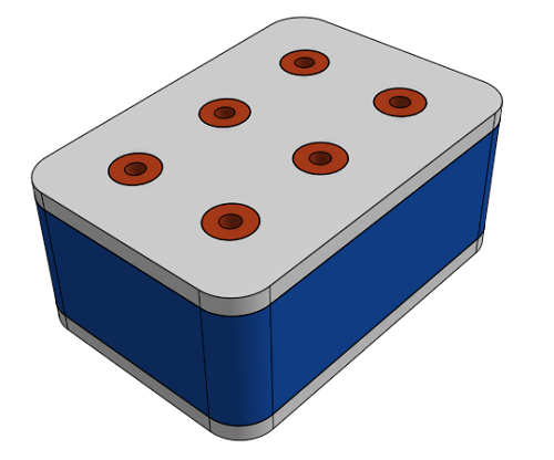
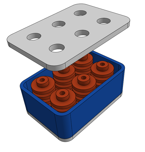
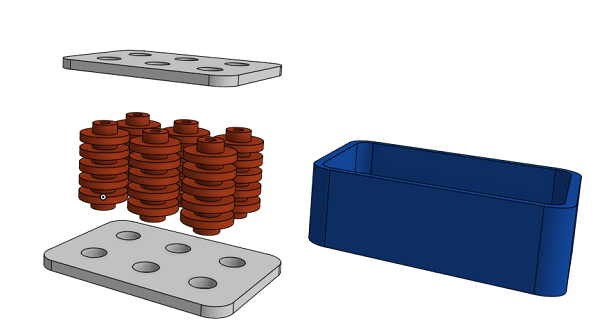
The two white parts would be made of aluminum,
The orange ones are your copper heatsinks. It's possible that they would need to be slightly modified, but nothing really difficult if you have a lathe around
The blue one can just be 3D printed.The idea is to sandwich the heatsinks between those two aluminum plates and have a 3D printed aluminum sleeve around to keep the water in. I made the sketch very basic but you'd need some grooves in the aluminum plate to ensure a good seal, as well as water inlets/outlets and screws to tighten everything.
The bottom plate would need to be slightly separated from your current heating block, I guess 6 washers should do the trick.
To seal everything, the easiest way is to use some automotive sealant, it is made for high temperatures, it's cheap and it's easy to do

Hope it helps !
-
I think heat breaks without heatsinks would work too. This doesn't help Ian because E3D doesn't make a PTFE-lined heat break without heatsink.
-
I plan to order this heatbreak, which is very well done, because of using copper where good thermal conductivity is needed, and stainless steel where bad thermal conductivity is needed.
It is then very easy to integrate it in a bloc of aluminium, drilled with a few holes to have water circulation:
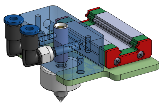
(the hole on the bottom-left needs to be closed by a screw+gasket)
The only problem is the price
 Especially when you need 6 of them! But they may give you some...
 -
@MrDui Funnily enough, my first cooling "tank" design use just that approach - but with simple tubes rather than the finned type. From other designs that I've looked at, the fins are not necessary when liquid cooling is used. But I had problems with leaks around the tubes. That was why I changed the lower part to one piece block with the tubes effectively milled out of a solid part.
For info, the liquid cooling system works just fine - I don't need to change it. The issue I have to resolve is filament leakage around the heat breaks where they are a press fit into a plate. The next design has screw threaded heat breaks which I hope will cure that problem.
-
@fma Yes, I've looked at the copper head and Slice engineering's liquid cooling designs too...(and every other "off the shelf" heat break that I can find).
My problem is that I have 6 inputs but only one output. With that type of heat break, the normal method of getting everything to seal is that the nozzle is tightened against the heat break. But I can't do that. So I need the heat break to have flats or a hexagonal section, so that it can be tightened against a flat plate. And it needs to be 4mm ID so that I can use a PTFE insert. So I'm having to make them. But they will look very similar to the heat breaks in the design you posted - just with flats or a hexagonal section so that they can be tightened.
Essentially, the cooling system and heat breaks worked well. It's just that I had filament leaks because press fitting the heat breaks into a flat plate didn't work well.
-
@MrDui For info, this was my first attempt at the simpler "tubular" design
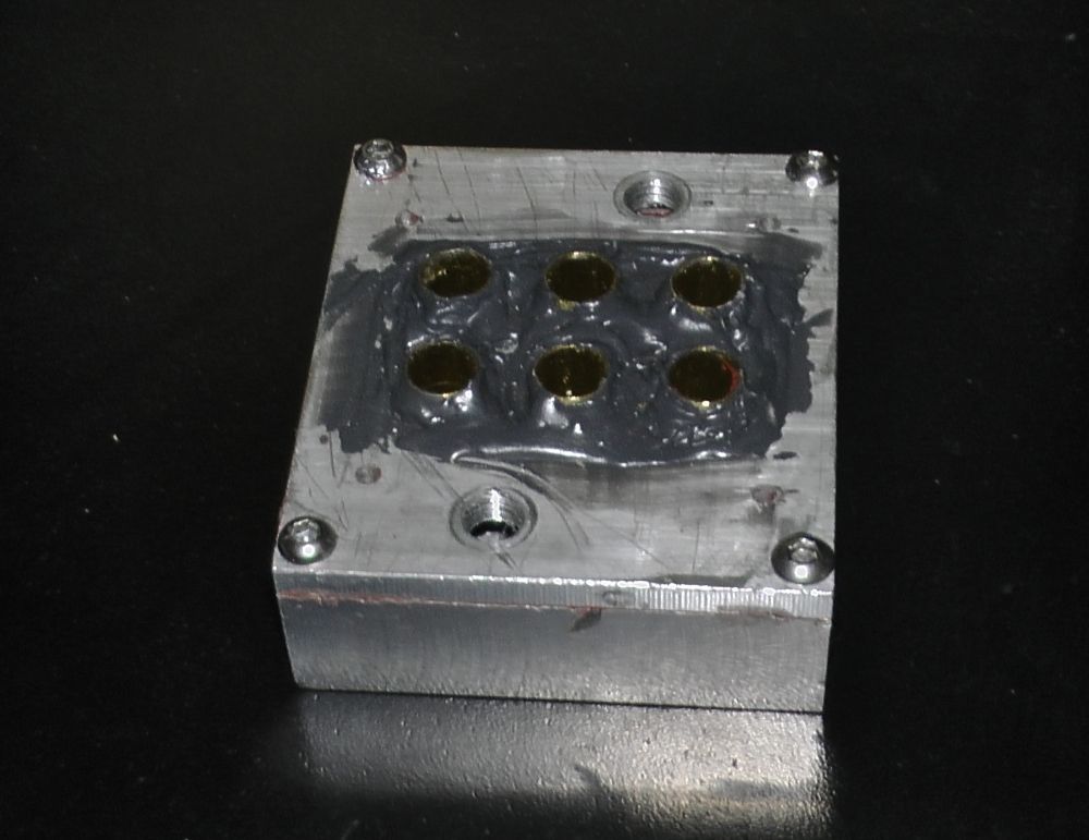
Despite copious amounts of sealant, I still had leaks.
-
I don't know if they exist in such small size, but you may search for copper gaskets used on cars oil tanks: https://www.ebay.com/p/202950637
They are crushed during tightening, and handle high temperature.
-
Did you see this one? It can be tighten with a spanner, but I don't know how torque it can handle...
-
@fma said in My 6 input (5+1) mixing hot end:
Did you see this one? It can be tighten with a spanner, but I don't know how torque it can handle...
Yes I did. But it's "all metal" so only 2mm or so ID (internal diameter) and mixing hot ends need to have PTFE lined heat breaks.
-
Ah, sorry, I forgot that point...
-
@fma said in My 6 input (5+1) mixing hot end:
Ah, sorry, I forgot that point...
No worries - thanks for trying

-
I'm wondering how these heatbreaks are made: are they just brut force-fitted?
-
@fma said in My 6 input (5+1) mixing hot end:
I'm wondering how these heatbreaks are made: are they just brut force-fitted?
The Mosquito ones? I wish I knew. I've asked the question of Slice Engineering but they didn't answer - guess it's a trade secret.
To me, as an engineer, it's some sort of dark magic. The tubes are really, really, seriously, thin - very easy to bend or crush (I know from experience). So if they are press fit, then they must use a tool of some sort which is very good fit inside the tube to prevent it from crushing. Even then, I can't see how it can be a press fit. But the magic doesn't end there because they are stainless steel tubes, fitted inside a copper nut. Copper has a much higher coefficient of thermal expansion than stainless steel, so one would expect the tubes to come loose at high temperature but they don't. Maybe they use some sort of high temperature adhesive but there is no sign of any residue.
If I knew the answer, then it would reasonably easy to replicate using thin wall 4mm ID stainless tube which would take a PTFE liner, instead of the 2mm that Slice Engineering use.
-
Perhaps by using hot crimping?