• Tags
  • Documentation
  • Order
  • Register
  • Login
Duet3D Logo Duet3D
  • Tags
  • Documentation
  • Order
  • Register
  • Login

External 5V source through duet3?

Scheduled Pinned Locked Moved
Duet Hardware and wiring
7
21
766
Loading More Posts
  • Oldest to Newest
  • Newest to Oldest
  • Most Votes
Reply
  • Reply as topic
Log in to reply
This topic has been deleted. Only users with topic management privileges can see it.
  • undefined
    oliof
    last edited by 9 Nov 2020, 16:16

    I planned on going to 5.1v like the official RPi power supplies, but 5.2 should give me a bit of headroom. I'll likely power the rpi directly.

    <>RatRig V-Minion Fly Super5Pro RRF<> V-Core 3.1 IDEX k*****r <> RatRig V-Minion SKR 2 Marlin<>

    undefined 1 Reply Last reply 9 Nov 2020, 16:36 Reply Quote 0
    • ?
      A Former User
      last edited by 9 Nov 2020, 16:20

      Yeah, I'd push it to the max, the 4B gives warnings even with the official Pi USB C supply when loaded but 5.25v when idle at the 5V pins makes it happy shiny. (Or you could just ignore the warning and disable the throtthling if you don't use hdmi or usb 5v out)

      1 Reply Last reply Reply Quote 0
      • undefined
        oozeBot @oliof
        last edited by oozeBot 11 Sept 2020, 16:39 9 Nov 2020, 16:36

        @oliof see the tail end of this thread for how we achieved this.. but now David has me wondering if I should reduce it to 5.2v instead of ~5.33v.

        https://forum.duet3d.com/topic/18725/how-big-a-5v-power-supply-needed-for-duet-3-and-rpi4

        1 Reply Last reply Reply Quote 1
        • undefined
          oliof
          last edited by oliof 11 Sept 2020, 21:08 9 Nov 2020, 21:07

          @oozeBot thanks for the link! Can you provide a schematic drawing of the full SSR circuit? Is it to switch the 24PSU for VIN which is not in the picture?

          <>RatRig V-Minion Fly Super5Pro RRF<> V-Core 3.1 IDEX k*****r <> RatRig V-Minion SKR 2 Marlin<>

          undefined 1 Reply Last reply 9 Nov 2020, 21:22 Reply Quote 0
          • undefined
            oozeBot @oliof
            last edited by 9 Nov 2020, 21:22

            @oliof Yes, the SSR toggles the 24v power supply (which is not in the photo). I'll see how soon I can whip up the schematics, but briefly, the positive SSR terminal is wired to the positive terminal on the 5v power supply. Ground is wired to PSON (between +5v and GRD in the EXT 5V header). It is toggled by gCode M80.

            Check out the power toggle script we are using here:

            https://forum.duet3d.com/topic/18848/duet-3-rpi-power-toggle-script

            1 Reply Last reply Reply Quote 0
            • undefined
              oliof
              last edited by 9 Nov 2020, 21:23

              Awesome, thanks! This will likely make the effort worth adding the extra PSU.

              <>RatRig V-Minion Fly Super5Pro RRF<> V-Core 3.1 IDEX k*****r <> RatRig V-Minion SKR 2 Marlin<>

              1 Reply Last reply Reply Quote 0
              • undefined
                oliof @dc42
                last edited by oliof 15 Nov 2020, 11:25

                With a MeanWell LRS-50-5 powering the Duet board at 5.25V, and the Duet board powering a Raspberry Pi 3B+, I still get undervoltage alerts from the Raspberry Pi. the voltage at the ribbon end plugging into the Pi is 5.17v.

                Since the ribbon cable blocks the power pins I could use for direct powering of the Pi, does this mean I am stuck with using the Micro USB port to power the Pi? Or could I modify my ribbon cable (disconnecting the 5V wires from the Duet3, and splicing in the external PSU there)?

                <>RatRig V-Minion Fly Super5Pro RRF<> V-Core 3.1 IDEX k*****r <> RatRig V-Minion SKR 2 Marlin<>

                undefined 1 Reply Last reply 15 Nov 2020, 11:55 Reply Quote 0
                • undefined
                  jay_s_uk @oliof
                  last edited by 15 Nov 2020, 11:55

                  @oliof you could always solder to the underside of the pi near the USB cable to inject 5v. That's what I do

                  Owns various duet boards and is the main wiki maintainer for the Teamgloomy LPC/STM32 port of RRF. Assume I'm running whatever the latest beta/stable build is

                  1 Reply Last reply Reply Quote 0
                  • undefined
                    oliof
                    last edited by 15 Nov 2020, 11:57

                    @jay_s_uk thanks for the suggestion! I'll think about it. Of course, now after having acquired and built the external PSU, and not getting any good results from it, powering from the duet3 seems to work again. Maybe disconnecting all the things for measuring voltages and reconnecting them helped with surfaces mating better ... it's too early to call this solved, but I will give it another test print.

                    <>RatRig V-Minion Fly Super5Pro RRF<> V-Core 3.1 IDEX k*****r <> RatRig V-Minion SKR 2 Marlin<>

                    1 Reply Last reply Reply Quote 0
                    • ?
                      A Former User
                      last edited by 15 Nov 2020, 13:09

                      Might be easier to solder to the 5V pins on the GPIO header if you go that route.

                      You could just add a IDC connector to the ribbon cable and T off that; or I opted for making a custom ribbon cable that extends past the Pi to the PSU in an earlier iteration.

                      1 Reply Last reply Reply Quote 1
                      • undefined
                        gloomyandy
                        last edited by 15 Nov 2020, 13:33

                        There is some additional protection (and possibly conditioning?) if you supply 5V via the USB connector though.

                        1 Reply Last reply Reply Quote 0
                        • ?
                          A Former User
                          last edited by 15 Nov 2020, 13:58

                          Hm, 3b+ still has a PTC 4b does not. Have 0 faith the pmic won't pack it before the the PTC so don't think I'd care and it's unlikely to help with voltage drops in the first place.

                          1 Reply Last reply Reply Quote 0
                          • undefined
                            gloomyandy
                            last edited by 15 Nov 2020, 14:14

                            I was thinking more about the DMG2305UX and associated circuitry on the 3B+ but that all seems to be gone on the 4. I powered my Pi 4 directly via the GPIO pins, but I did have a lot of low voltage events. I suspect that was the dodgy buck converter I was using as much as anything though.

                            1 Reply Last reply Reply Quote 0
                            • ?
                              A Former User
                              last edited by A Former User 15 Nov 2020, 14:52

                              Can't say I saw much but the fuse?
                              93141b1c-4754-4afc-8d6c-eef1ab8b8ede-image.png
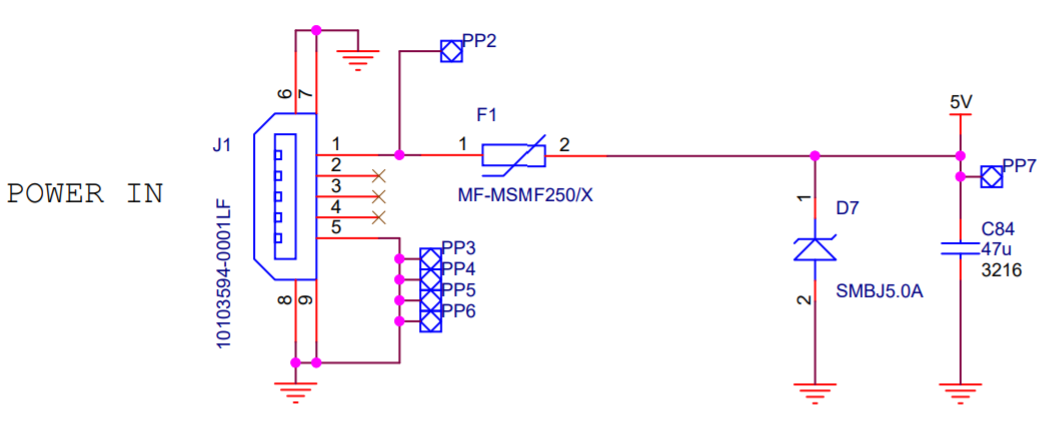
                              https://www.raspberrypi.org/documentation/hardware/raspberrypi/schematics/rpi_SCH_3bplus_1p0_reduced.pdf

                              1 Reply Last reply Reply Quote 0
                              • undefined
                                gloomyandy
                                last edited by 15 Nov 2020, 15:02

                                @bearer Take a look at the rev1.2 version...
                                https://www.raspberrypi.org/documentation/hardware/raspberrypi/schematics/rpi_SCH_1bplus_1p2_reduced.pdf

                                1 Reply Last reply Reply Quote 0
                                • ?
                                  A Former User
                                  last edited by 15 Nov 2020, 15:05

                                  Google-fail; but still not seeing the value if not using the micro USB port you don't need to prevent back feeding 5V to USB and if one need reverse polarity protection then I guess one might already be in dangerous waters.

                                  1 Reply Last reply Reply Quote 0
                                  • undefined
                                    gloomyandy
                                    last edited by 15 Nov 2020, 15:16

                                    Oh I'm not arguing after all I didn't use it either, but having said that the direct gpio connection didn't work particularly well for me either! The same pi with a (not particularly good USB) power supply runs without any voltage warnings, I'm not really sure why, dodgy buck converter, dodgy gpio connector, or dodgy wiring (well relatively thin ribbon cable wiring), take your pick!

                                    1 Reply Last reply Reply Quote 0
                                    14 out of 21
                                    • First post
                                      14/21
                                      Last post
                                    Unless otherwise noted, all forum content is licensed under CC-BY-SA