Mesh Compensation working only half of the built plate
-
Upgraded my Tevo Tornado with a Duet 2 Wifi board. I never was able to get the mesh bed leveling working 100%. Today I updated to the newer firmware 3. Hoping that could help. After making all changes it seems to be working just the same way. On the right side of the bed everything is loose and the left side smashed into the bed. I have a BLtouch. As soon as I get to the printer I will post config.g bed.g and the heightmap. If there is anything else I can get config wise let me know.
-
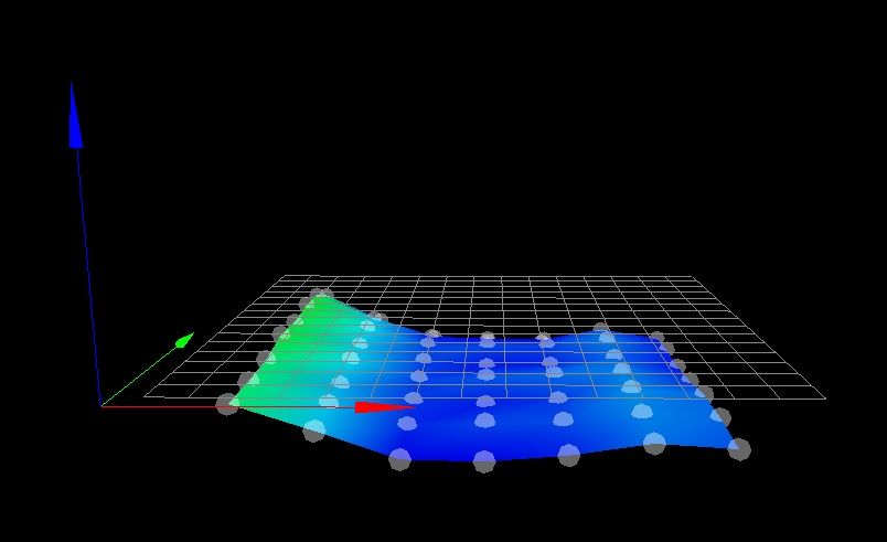
; Configuration file for Duet WiFi (firmware version 3)
; executed by the firmware on start-up
;
; generated by RepRapFirmware Configuration Tool v3.1.4 on Sun Nov 15 2020 13:08:08 GMT-0800 (Pacific Standard Time)

; General preferences
G90                                                ; send absolute coordinates...
M83                                                ; ...but relative extruder moves
M550 P"TevoTornado 2"                              ; set printer name

; Network
M552 S1                                            ; enable network
M586 P0 S1                                         ; enable HTTP
M586 P1 S0                                         ; disable FTP
M586 P2 S0                                         ; disable Telnet

; Drives
M569 P0 S0                                         ; physical drive 0 goes backwards
M569 P1 S0                                         ; physical drive 1 goes backwards
M569 P2 S0                                         ; physical drive 2 goes backwards
M569 P3 S0                                         ; physical drive 3 goes backwards
M584 X0 Y1 Z2 E3                                   ; set drive mapping
M350 X16 Y16 Z16 E16 I1                            ; configure microstepping with interpolation
M92 X80.00 Y80.00 Z800.00 E127.00                  ; set steps per mm
M566 X900.00 Y900.00 Z12.00 E120.00                ; set maximum instantaneous speed changes (mm/min)
M203 X180000.00 Y180000.00 Z6000.00 E1200.00       ; set maximum speeds (mm/min)
M201 X500.00 Y500.00 Z20.00 E250.00                ; set accelerations (mm/s^2)
M906 X800 Y800 Z800 E950 I5                        ; set motor currents (mA) and motor idle factor in per cent
M84 S30                                            ; Set idle timeout

; Axis Limits
M208 X0 Y0 Z0 S1                                   ; set axis minima
M208 X310 Y310 Z400 S0                             ; set axis maxima

; Endstops
M574 X1 S1 P"!xstop"                                ; configure active-high endstop for low end on X via pin xstop
M574 Y1 S1 P"!ystop"                                ; configure active-high endstop for low end on Y via pin ystop
M574 Z1 S2                                         ; configure Z-probe endstop for low end on Z

; Z-Probe
M950 S0 C"exp.heater3"                             ; create servo pin 0 for BLTouch
M558 P9 C"^zprobe.in" H5 F120 T6000                ; set Z probe type to bltouch and the dive height + speeds
G31 P500 X-45.25 Y-8.28 Z3.53                      ; set Z probe trigger value, offset and trigger height
M557 X5:265 Y5:265 S52                            ; define mesh grid

; Heaters
M308 S0 P"bedtemp" Y"thermistor" T100000 B4138                ; configure sensor 0 as PT1000 on pin bedtemp
M950 H0 C"bedheat" T0                              ; create bed heater output on bedheat and map it to sensor 0
M307 H0 B0 S1.00                                   ; disable bang-bang mode for the bed heater and set PWM limit
M140 H0                                            ; map heated bed to heater 0
M143 H0 S120                                       ; set temperature limit for heater 0 to 120C
M308 S1 P"e0temp" Y"thermistor" T100000 B4138	   ; sensor 1                  ; configure sensor 1 as PT1000 on pin e0temp
M950 H1 C"e0heat" T1 							   ; create heater and map sensor 1                               ; create nozzle heater output on e0heat and map it to sensor 1
M307 H1 B0 S1.00                                   ; disable bang-bang mode for heater  and set PWM limit


; Fans
M950 F0 C"fan0" Q500                               ; create fan 0 on pin fan0 and set its frequency
M106 P0 S0 H-1                                     ; set fan 0 value. Thermostatic control is turned off
M950 F1 C"fan1" Q500                               ; create fan 1 on pin fan1 and set its frequency
M106 P1 S1 H1 T45                                  ; set fan 1 value. Thermostatic control is turned on
M950 F2 C"fan2" Q500                               ; create fan 2 on pin fan2 and set its frequency
M106 P2 S0.5 H-1                                   ; set fan 2 value. Thermostatic control is turned off

; Tools
M563 P0 D0 H1 F0                                   ; define tool 0
G10 P0 X0 Y0 Z0                                    ; set tool 0 axis offsets
G10 P0 R0 S0                                       ; set initial tool 0 active and standby temperatures to 0C

; Custom settings are not defined

; Miscellaneous
M911 S10 R11 P"M913 X0 Y0 G91 M83 G1 Z3 E-5 F1000" ; set voltage thresholds and actions to run on power loss
M501


after updating to v3 today I got a message that the G32 will be no longer supported so take it out I guess?
RepRapFirmware height map file v2 generated at 2020-11-15 14:34, min error -0.197, max error 0.076, mean -0.085, deviation 0.066 xmin,xmax,ymin,ymax,radius,xspacing,yspacing,xnum,ynum 5.00,265.00,5.00,265.00,-1.00,52.00,52.00,6,6 0.076, 0.001, -0.086, -0.054, -0.030, 0 -0.010, -0.120, -0.145, -0.089, -0.041, 0 0.004, -0.101, -0.170, -0.125, -0.071, 0 -0.020, -0.132, -0.160, -0.108, -0.081, 0 -0.016, -0.160, -0.197, -0.131, -0.054, 0 0.025, -0.132, -0.178, -0.142, -0.094, 0this could be set back to M561 G29 delete the rest since it will be no longer supported?
bed.g ; called to perform automatic bed compensation via G32 ; ; generated by RepRapFirmware Configuration Tool v3.1.4 on Sat Sep 05 2020 23:38:17 GMT-0700 (Pacific Daylight Time) M561 ; clear any bed transform G29 S2 ; probe the bed and enable compensation //S2 ; Probe 2-point M401 ; Deploy probe - deployprobe.g G30 P0 X5 Y5 Z-9999 ; Middle Left G30 P1 X5 Y285 Z-9999 ; Middle Right G30 P2 X285 Y285 Z-9999 ; Middle Right G30 P3 X285 Y5 Z-9999 S4 ; Middle Right M402 ; Retract Probe - retractprobe.g -
After playing around with the M557 and looking at the heightmap, I am curious if the problem could be the probe only goes to X 255mm as most far but the print is beyond it?
-
It sounds like you’ve figured it out.
Your probe offset is -45mm in the X so it may not be able to probe the x=285 points as you stated. It will probe only what it can reach.
Check the Height Map option in the DWC and make sure you see 4 points. I think the console will also echo failure. You can also view the heighmap.csv in System.
-
Warning: Skipping grid point (305.0, 85.0) because Z probe cannot reach ityes it does that. But does that really explain all my problems? Left side to close, right side too far?
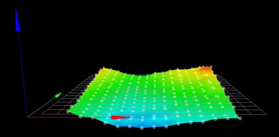
I checked the DWC and I see more then 4 points as you can see in the 2nd code box.I changed the x-axis max to 345 and now it can reach more (X 280mm) testing a print soon to see if that changes anything.
Here is the result of the mesh:
  0.106,  0.099, -0.021,  0.019,  0.029,  0.019,  0.017,  0.044,  0.082,  0.112,  0.106,  0.129,  0.156,  0.151,  0.341,      0,      0,      0
  0.142,  0.125,  0.091,  0.041,  0.035,  0.030,  0.029,  0.019,  0.054,  0.085,  0.076,  0.069,  0.082,  0.064,  0.283,      0,      0,      0
  0.101,  0.085,  0.051,  0.010,  0.020,  0.017,  0.017,  0.014,  0.059,  0.095,  0.084,  0.111,  0.131,  0.140,  0.305,      0,      0,      0
  0.107,  0.072,  0.053,  0.014, -0.003, -0.006,  0.007, -0.008,  0.039,  0.061,  0.057,  0.077,  0.070,  0.069,  0.273,      0,      0,      0
  0.114,  0.091,  0.057,  0.017, -0.010, -0.001,  0.005, -0.003,  0.036,  0.047,  0.051,  0.079,  0.090,  0.094,  0.247,      0,      0,      0
  0.121,  0.087,  0.066,  0.019, -0.004,  0.006,  0.015,  0.002,  0.050,  0.056,  0.059,  0.064,  0.067,  0.062,  0.244,      0,      0,      0
  0.090,  0.057,  0.050,  0.001, -0.025,  0.002,  0.000, -0.018,  0.039,  0.057,  0.064,  0.064,  0.100,  0.102,  0.255,      0,      0,      0
  0.107,  0.065,  0.056,  0.005, -0.025,  0.011,  0.000, -0.008,  0.043,  0.047,  0.050,  0.039,  0.049,  0.050,  0.220,      0,      0,      0
  0.146,  0.105,  0.090,  0.021, -0.014,  0.016, -0.010, -0.008,  0.019,  0.041,  0.045,  0.023,  0.055,  0.045,  0.194,      0,      0,      0
  0.115,  0.076,  0.074,  0.015, -0.013,  0.013,  0.002,  0.006,  0.031,  0.055,  0.061,  0.034,  0.045,  0.031,  0.215,      0,      0,      0
  0.114,  0.079,  0.070,  0.004, -0.025, -0.008, -0.008,  0.001,  0.013,  0.046,  0.059,  0.040,  0.081,  0.066,  0.231,      0,      0,      0
  0.134,  0.097,  0.071,  0.013, -0.020, -0.010, -0.010, -0.003,  0.004,  0.030,  0.046,  0.021,  0.046,  0.025,  0.219,      0,      0,      0
  0.095,  0.061,  0.044, -0.016, -0.044, -0.046, -0.036, -0.016, -0.004,  0.034,  0.045,  0.024,  0.081,  0.070,  0.235,      0,      0,      0
  0.116,  0.077,  0.051,  0.009, -0.014, -0.028, -0.021, -0.005,  0.002,  0.054,  0.054,  0.031,  0.060,  0.047,  0.250,      0,      0,      0
rerunning it to compare
-
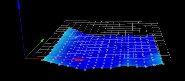
first test print just confirmed that nothing has changed. left side too close right not close enough
-
How bout a screenshot of your heightmap being displayed in DWC? I don't really want to fire up excel to make a graph of your bed map.
@R3D8U1L said in Mesh Compensation working only half of the built plate:
after updating to v3 today I got a message that the G32 will be no longer supported so take it out I guess?
This is referring to your bed.g using 4 points to create a plane. This method is replaced by using G29 which is far more capable.
@R3D8U1L said in Mesh Compensation working only half of the built plate:
yes it does that. But does that really explain all my problems? Left side to close, right side too far?
That could be part of it, but the mesh will actually be extrapolated by the firmware out to areas it can't reach, though that's imperfect guessing compared to actual probe data.
It might also be a problem with tilt of your X axis, either of the X gantry, or the bed plane, or the printhead/probe leading to different trigger heights based on XY position.
You can test this by doing the trigger height measurement (g30 S-1) at different locations on the bed to see if they are consistent. This is bvery common in delta printers where the effector is tilted causing the offset probe to read differently based on where on the bed it is positioned. But it can also happen with other kinematics. Having the probe offset far from the nozzle makes it worse because even a small tilt can be exacerbated by the distance.
After doing the G30 S-1 test (same as shown here to get the trigger height for G31 https://duet3d.dozuki.com/Wiki/Test_and_calibrate_the_Z_probe) at different points on the bed you should have an idea if it's consistent or not.
Another way of testing is to change your probe type to M558 P0 which is manual probing. That allows you to manually jog the nozzle down to touch the bed, removing the probe entirely. You might not want to do a detailed mesh with that method, but if you do a M557 with P4 to set 4 points it would behave the same as your 4 point leveling in bed.g which is no longer used.
If using the manual probe in the 4 corners creates a flat plane and the bed is generally pretty flat your resulting first layer shouldn't be squished or high on either side.
-
No even with the older version 2.05? I believe it was the same exact problem.
G32 in bed.g is disabled again only using G29
I was hoping it would extrapolate the data, but was not sure.
Will do the tests with G30 S-1 and report as soon as I am done.
I did run the Calibration of the Z offset, if I remember correctly, 3x 3.78 3.82 and 3.83
-
Here are some results, hope I did it right:
x50 	y50 	3.495 mm
x100 	y50	3.406 mm
x150	y50	3.312 mm
x200	y50	3.331 mm
x250	y50	3.362 mm
x300	y50	3.360 mm
x50	y100	3.511 mm
x50	y150	3.483 mm
x50	y200	3.483 mm
x50	y250	3.499 mm
x50	y300	3.546 mm
will that not show the same like the heightmap?
-
Based on those numbers it does seem like you have a different trigger height from the left side to the right side.
3.495 vs 3.360
Try and get your printer squared up as much as possible. In a cartesian bed slider the bed (Y) and gantry (X) must be totally aligned. Mesh compensation can correct for a lot, but it assumes that the probe to nozzle offset is consistent regardless of XY position. There are certain mechanical situations such as skew of the X and Y axis that it can't really compensate for if the probe has an offset from the nozzle.
-
@Phaedrux said in Mesh Compensation working only half of the built plate:
Based on those numbers it does seem like you have a different trigger height from the left side to the right side.
3.495 vs 3.360
Try and get your printer squared up as much as possible. In a cartesian bed slider the bed (Y) and gantry (X) must be totally aligned. Mesh compensation can correct for a lot, but it assumes that the probe to nozzle offset is consistent regardless of XY position. There are certain mechanical situations such as skew of the X and Y axis that it can't really compensate for if the probe has an offset from the nozzle.
working on the tomorrow and keep you posted. It makes sense that its from hardware side since it has been consistent in any firmware.
-
If there any way to modify the probe mounting position to get it closer to the nozzle? That can be a big help. It's also ideal to have it directly inline with the nozzle in at least one of the axis, preferably Y, due to the way the print head mounts tend to stick out in Y and the weight can cause some droop/twist.
-
in this case I would need a mount for a micro swiss direct drive extruder with the probe in line with the Y axis. Hope google can help me there.
-
Your Y offset is only 8mm, so it's not that bad. It's really the 45mm in x that is the main issue. Even so, that doesn't address the root problem of XY skew.
-
This is what I am using so no modification possible I believe.
I need to be educated. If the probe does the mesh level, it is at the same position the nozzle will be later when printing. Why does the offset effect it so much?
-
@Phaedrux if it would bin in line on the Y and closer to the nozzle? SO offset would be x+- 10 and y also +-10?
-
@R3D8U1L instead of software reasons, I can think of mechanical reasons also. Looking at your printer model, I think of
- bed could bend, is it heated while you test? Are the screws very stiff and thermal expansion bent at the side where the screws are most stiff
- gantry aluminium extrusion of x axis could be bent near the low x position
- hotend could be pressed up (or tilted) in low x position due to bowden, resulting in high Z values
IMHO the third possibility is the most probable, I would test this first by checking whether the bowden cable is under pressure when the x position is low.
-
@JoergS5 It's a glass bed. I think they are unlikely to bend?
Yes I heat it to regular PLA temp of 65C for first layer.
I just took all the gantry apart and assembled it with 90 degree on one site the other I could only manage 80.5.Here before and after mechanical changes:
before:
after:
I have noticed everything is "low" now.
As far as for the hotend, the bowden tube to me looks very free on the first layer printing. Can you describe this more in detail?

talking about the stiff screws, do you mean the adjuster knobs? Cause they are pretty stiffened up. Maybe loosen them all the way and just go back a bit to set in place?

-
@R3D8U1L using the calculator https://goodcalculators.com/thermal-expansion-calculator/ glass expands about 0.1 mm with 30 cm and 50 degree change.
I then used https://www.arndt-bruenner.de/mathe/scripts/kreissehnen.htm to calculate how much the bed would go up, using s=30 and b=30.1, resulting in a=1, which means it would bend and go up 1 cm if it would be really fixed. But of course the screws and other elements will bend more. It depends on the strengths of all materials how much the glass, screws or aluminium plate below bend, aluminium most of course. *)
*) I correct myself: E-module of glass is 40...90, aluminium 70, steel 180...210 GPa, so glass will bend comparable to aluminium. How much the steel screws bend, depends on the diameter and length of the screws.
I meant the 4 screws which fix the bed. You could try loosing 3 of them (with loosing I mean they can let the glass change xy positions, but not Z) and 1 fixed. If the boring holes are a bit bigger than the screws, the bed could "flee" a bit from the thermal expansion. If the holes are too small, I would use smaller diameter screws, this is much easier than boring bigger holes into glass... (but in general boring holes are bigger than the screws, more than 0.1 mm bigger).
Fixing at only one point only is only for testing whether it solves your problem. In the long run the bed moves and fixing at one point is not enough to protect against rotation.
-
@R3D8U1L the (
bowden)/wire connected to the extruder/hotend is loose, this will not be the reason. (I thought it has Bowden because the original printer I saw advertised used bowden)