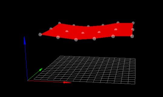
Mesh Compensation working only half of the built plate
-
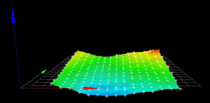
Based on those numbers it does seem like you have a different trigger height from the left side to the right side.
3.495 vs 3.360
Try and get your printer squared up as much as possible. In a cartesian bed slider the bed (Y) and gantry (X) must be totally aligned. Mesh compensation can correct for a lot, but it assumes that the probe to nozzle offset is consistent regardless of XY position. There are certain mechanical situations such as skew of the X and Y axis that it can't really compensate for if the probe has an offset from the nozzle.
-
@Phaedrux said in Mesh Compensation working only half of the built plate:
Based on those numbers it does seem like you have a different trigger height from the left side to the right side.
3.495 vs 3.360
Try and get your printer squared up as much as possible. In a cartesian bed slider the bed (Y) and gantry (X) must be totally aligned. Mesh compensation can correct for a lot, but it assumes that the probe to nozzle offset is consistent regardless of XY position. There are certain mechanical situations such as skew of the X and Y axis that it can't really compensate for if the probe has an offset from the nozzle.
working on the tomorrow and keep you posted. It makes sense that its from hardware side since it has been consistent in any firmware.
-
If there any way to modify the probe mounting position to get it closer to the nozzle? That can be a big help. It's also ideal to have it directly inline with the nozzle in at least one of the axis, preferably Y, due to the way the print head mounts tend to stick out in Y and the weight can cause some droop/twist.
-
in this case I would need a mount for a micro swiss direct drive extruder with the probe in line with the Y axis. Hope google can help me there.
-
Your Y offset is only 8mm, so it's not that bad. It's really the 45mm in x that is the main issue. Even so, that doesn't address the root problem of XY skew.
-
This is what I am using so no modification possible I believe.
I need to be educated. If the probe does the mesh level, it is at the same position the nozzle will be later when printing. Why does the offset effect it so much?
-
@Phaedrux if it would bin in line on the Y and closer to the nozzle? SO offset would be x+- 10 and y also +-10?
-
@R3D8U1L instead of software reasons, I can think of mechanical reasons also. Looking at your printer model, I think of
- bed could bend, is it heated while you test? Are the screws very stiff and thermal expansion bent at the side where the screws are most stiff
- gantry aluminium extrusion of x axis could be bent near the low x position
- hotend could be pressed up (or tilted) in low x position due to bowden, resulting in high Z values
IMHO the third possibility is the most probable, I would test this first by checking whether the bowden cable is under pressure when the x position is low.
-
@JoergS5 It's a glass bed. I think they are unlikely to bend?
Yes I heat it to regular PLA temp of 65C for first layer.
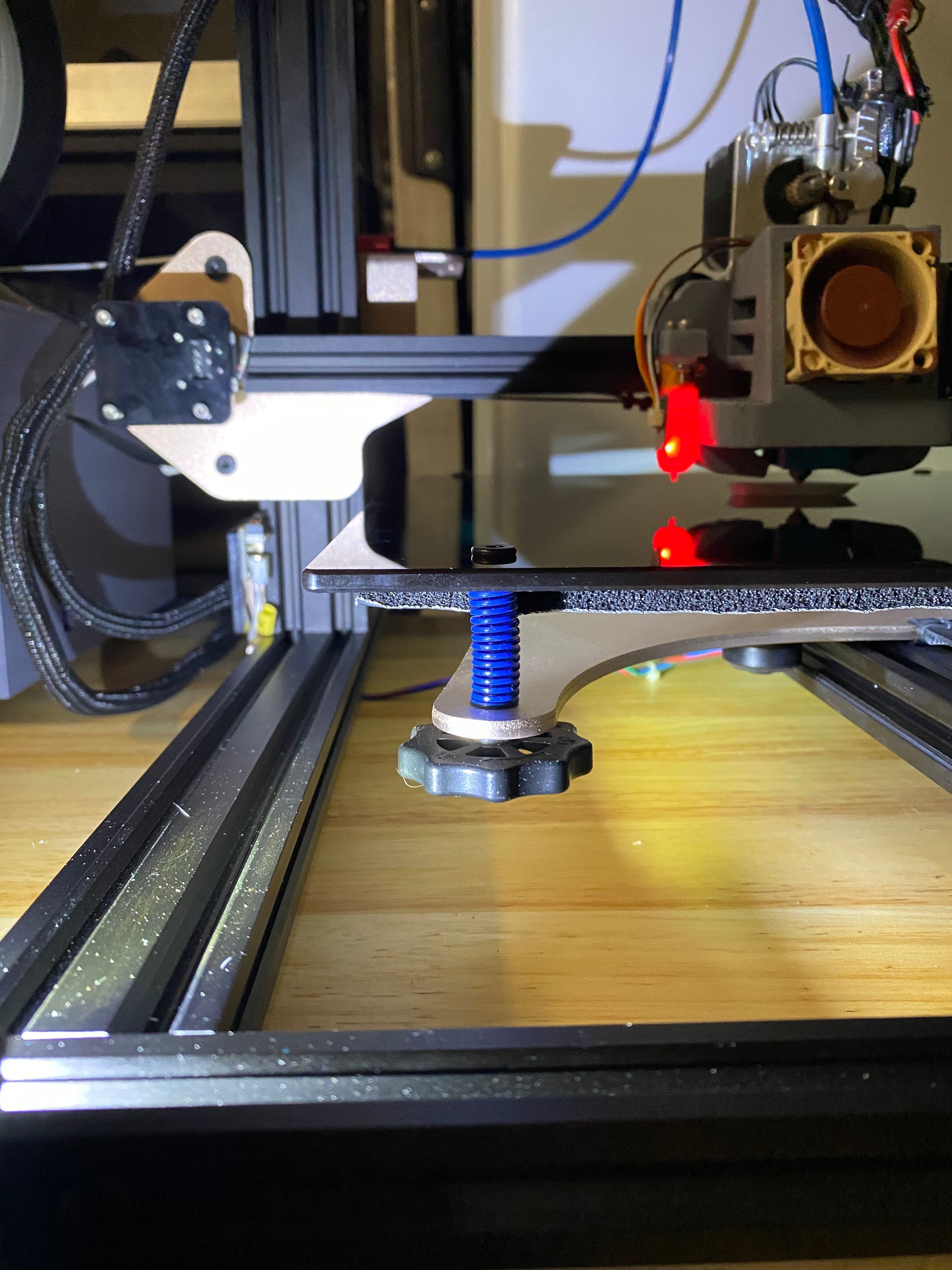
I just took all the gantry apart and assembled it with 90 degree on one site the other I could only manage 80.5.Here before and after mechanical changes:
before:
after:
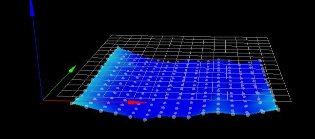
I have noticed everything is "low" now.
As far as for the hotend, the bowden tube to me looks very free on the first layer printing. Can you describe this more in detail?

talking about the stiff screws, do you mean the adjuster knobs? Cause they are pretty stiffened up. Maybe loosen them all the way and just go back a bit to set in place?

-
@R3D8U1L using the calculator https://goodcalculators.com/thermal-expansion-calculator/ glass expands about 0.1 mm with 30 cm and 50 degree change.
I then used https://www.arndt-bruenner.de/mathe/scripts/kreissehnen.htm to calculate how much the bed would go up, using s=30 and b=30.1, resulting in a=1, which means it would bend and go up 1 cm if it would be really fixed. But of course the screws and other elements will bend more. It depends on the strengths of all materials how much the glass, screws or aluminium plate below bend, aluminium most of course. *)
*) I correct myself: E-module of glass is 40...90, aluminium 70, steel 180...210 GPa, so glass will bend comparable to aluminium. How much the steel screws bend, depends on the diameter and length of the screws.
I meant the 4 screws which fix the bed. You could try loosing 3 of them (with loosing I mean they can let the glass change xy positions, but not Z) and 1 fixed. If the boring holes are a bit bigger than the screws, the bed could "flee" a bit from the thermal expansion. If the holes are too small, I would use smaller diameter screws, this is much easier than boring bigger holes into glass... (but in general boring holes are bigger than the screws, more than 0.1 mm bigger).
Fixing at only one point only is only for testing whether it solves your problem. In the long run the bed moves and fixing at one point is not enough to protect against rotation.
-
@R3D8U1L the (
bowden)/wire connected to the extruder/hotend is loose, this will not be the reason. (I thought it has Bowden because the original printer I saw advertised used bowden) -
It looks like we have a winner! Thank you so much Joerg55 and Phaedrux, I would never have thought about the glass bed changing with temperature, now it makes sense.

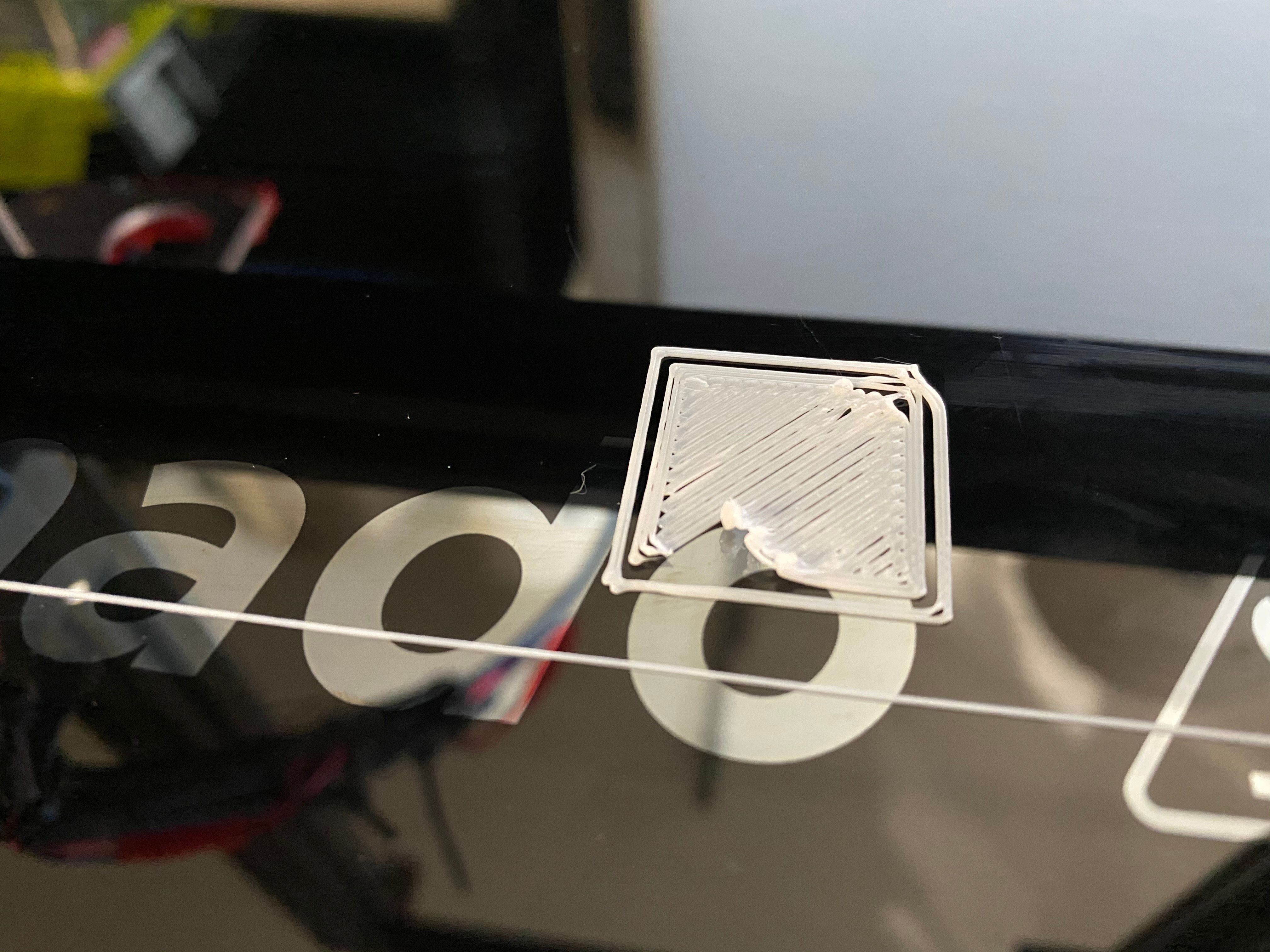
I got one small issue left, My filament starts to "roll" and sometimes stick to the nozzle and cause this:

is that a temperature issue?
-
@R3D8U1L said in Mesh Compensation working only half of the built plate:
is that a temperature issue?
It could be temperature, yes. Try upping the bed temp 5 to 10c.
Glass also needs to be quite clean to stick well, or use an additive like glue stick.
-
The upper-right corner looks like you are dragging filament around the corner.
That happens to me when I print the first layer too fast.
Can you try 1/4 speed and see if it improves things?
-
@Phaedrux I used a glue stick before, didn't like cleaning up after

I think the ambient temperature here is maybe causing another issue. its 18C roughly. At night even less. Ordered a chamber to help that. Will try lowering the speed and do a test print. -
@R3D8U1L said in Mesh Compensation working only half of the built plate:
I think the ambient temperature here is maybe causing another issue. its 18C roughly. At night even less.
Yes that could have an effect.
-
@alankilian Did run a test with 10mm/s instead of 30mm/s. It definitely helped. Have to find the sweet spot cause the print time on larger object will be significantly higher.
-
@R3D8U1L My slicer (Simplify3D) allows me to set an "Underspeed" for the first layer. I set it to 25% usually.
That way it's only slow for the first and most important layer.
Does your slicer offer such a setting?
-
@R3D8U1L nice to hear that your printing improved.
-
@alankilian Yes Prusa Slic3er does offer that. Like I said I am printing some different tests with first player speed and first layer bed temp to find the point where it goes from failing to working and hopefully keep those settings for all future prints.