Using M581 external triggers to make control panel issues
-
Could it be that the SPI pins you're using are being used for something else as well?
Any data traffic on that pin might execute the trigger.
I guess you could free the pin first but I don't know what RRF is using those pins for. -
@Phaedrux said in Using M581 external triggers to make control panel issues:
Maybe try adding a brief pause after the baby step command? G4 S1 for 1 second?
That seems to slow down the infinite loop with 1 second pauses in-between each baby step
@OwenD said in Using M581 external triggers to make control panel issues:
Could it be that the SPI pins you're using are being used for something else as well?
Any data traffic on that pin might execute the trigger.
I guess you could free the pin first but I don't know what RRF is using those pins for.I tried changing the pins in config.g
; Triggers
M950 J1 C"^exp.e2stop"			; create pin1 for baby step (+)
M581 T2 P1 S0 R0			; create trigger for pin1
;M950 J2 C"^exp.e3stop"			; create pin2 for baby step (-)
;M581 T3 P2 S1 R0			; create trigger for pin2
;M950 J3 C"^exp.e4stop"			; create pin3 for emergency stop
;M581 T0 P3 S1 R0			; create stop trigger for pin3
;M950 J4 C"^exp.e5stop"			; create pin4 for pause
;M581 T1 P4 S1 R0			; create stop trigger for pin4
for testing I am only uncommenting pin1 until I can get baby stepping(+) working.
Interesting thing happened while testing just pin1, the baby step button on DWC acts the same way as using trigger2.g.
So if trigger2.g has a G4 S1, the DWC button will mimic that with a one second pause while continuing an infinite loop. When I comment out the M950 and M581 for pin1, the baby step buttons on DWC act normal.
-
@jfitc004 said in Using M581 external triggers to make control panel issues:
M950 J1 C"spi.cs1"
M581 T2 P1 S1 R0-
Your switches pull the pin to ground, so you need to either invert the pin in the M950 command, or trigger on a low signal level (S0) instead of a high level (S1).
-
Enable the pullup resistor in the M950 command.
-
You may wish to add a G4 delay command in the macro file after the M291 command, to avoid contact bounce generating multiple triggers.
Duet WiFi hardware designer and firmware engineer
Please do not ask me for Duet support via PM or email, use the forum
http://www.escher3d.com, https://miscsolutions.wordpress.com -
-
@dc42 that definitely makes sense
so I should either have in my config.g
M950 J1 C"^spi.cs1"
M581 T2 P1 S0 R0
or
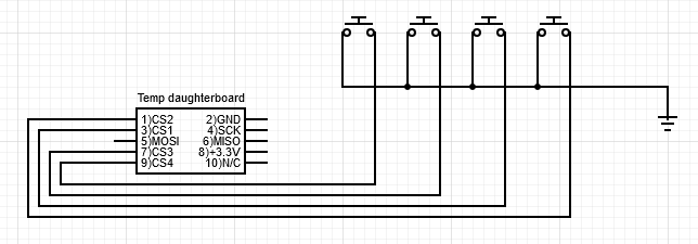
M950 J1 C"!^spi.cs1"
M581 T2 P1 S1 R0
and would either of these wiring diagrams work?
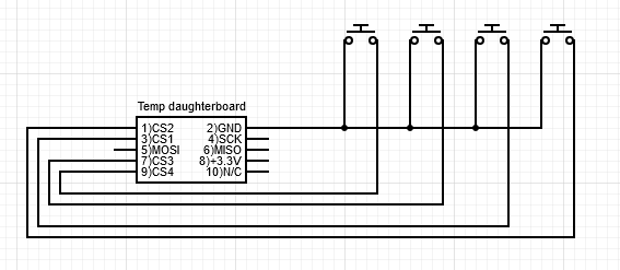
or
-
Yes. Best to use the ground on the daughter board for the switches, because the daughter board CS pins have no input protection apart from what's built into the MCU.
Duet WiFi hardware designer and firmware engineer
Please do not ask me for Duet support via PM or email, use the forum
http://www.escher3d.com, https://miscsolutions.wordpress.com -
@dc42 I think there might be something else going on. I wired it how you suggested and if I press my external switch, the babystep icon in DWC 'Status' or homeall in DWC 'Dashboard', the printer goes into a continuous loop of +0.01mm every 1 second until I restart using emergency stop. If I comment out M950 and M581 for external triggers the printer functions as expected.
trigger2.g
; trigger2.g
; baby stepping (+)

M400            ; wait for current move to finish
M290 R1 S0.01	; increase baby step by 0.01mm
G4 S1           ; one second pause
and here's my homeall.g
; homeall.g
; called to home all axes
;

G91                     ; relative positioning
G1 H2 Z5 F6000          ; lift Z relative to current position
M400			; Wait for current moves to finish
M913 X50 Y50 Z50	; Set motor percentage 50% of normal current
G1 H1 X-335 Y-335 F3000 ; move quickly to X or Y endstop and stop there (first pass)
G1 H1 X-335             ; home X axis
G1 H1 Y-335             ; home Y axis
G1 X5 Y5 F600           ; go back a few mm
G1 H1 X-335 F360        ; move slowly to X axis endstop once more (second pass)
G1 H1 Y-335             ; then move slowly to Y axis endstop
G1 H1 Z-380 F720 	; home Z axis
G1 Z5 F360 		; go back a few mm
G1 H1 Z-380 F360	; rehome Z axis at slower speed
G90			; absolute positioning
M400			; Wait for current moves to finish
M913 X100 Y100 Z100	; Set motor percentage to 100% normal current
Is there anything that looks suspect?
-
Upon further tinkering, it seems as though the for cs1, cs2, cs3 and cs4 pins for the temp daughterboard did not change behavior with NO-SPST switches for me. By using a spare makerbot mechanical endstop v1.2, I was able to get the desired behavior for trigger2.
I connected:
endstop 3.3v -----> to daughterboard 3.3v
endstop GND ----> to daughterboard GND
endstop output--> to daughterboard CS1and got the ideal expected results that I wanted.
Whether I used a '!' or not in M950 or 'S1' or 'S0' in M581 didn't make a difference in the intended behavior. Using the makerbot mechanical endstops is a temporary solution. If I want to use pins cs1-4 long term for my triggers without the current switches, I'll need to get some NC-SPST momentary switches.
So I am curious does my board have an issue if I cannot control the pin inversion or hi/lo signal with the firmware to have external triggers function with normally open switches?
-
I suspect that you forgot to enable the pullup resistors when you declared those SPI CS pins as inputs.
Duet WiFi hardware designer and firmware engineer
Please do not ask me for Duet support via PM or email, use the forum
http://www.escher3d.com, https://miscsolutions.wordpress.com -
@dc42 I am not sure what you mean. Is it not just simply adding a caret symbol at the beginning of the quoted C parameter in M950?
I was getting no change in behavior with these four different implementations with a SPST-NO switch.
M950 J1 C"^spi.cs1"
M581 T2 P1 S0 R0
M950 J1 C"!^spi.cs1" M581 T2 P1 S1 R0M950 J1 C"^spi.cs1" M581 T2 P1 S1 R0M950 J1 C"!^spi.cs1" M581 T2 P1 S0 R0The button press would invoke trigger2.g and would run it continuously until I held the button down or by attaching the pin to ground. So I would assume that inverting the pin or changing the trigger level from high to low or vice versa would fix that behavior but it didn't.
I am by no means an expert or pretend to be with gcode, I am just worried I did something to the board if it can't be solved with code.
Do I need to power off the board for the pullup resistors to function or is the restart after saving the config.g suffice?
Is it possible to use a multimeter to check high state or low state of the resistor? I am guessing its probably of the 4.7kΩ variety
-
@jfitc004 said in Using M581 external triggers to make control panel issues:
Do I need to power off the board for the pullup resistors to function or is the restart after saving the config.g suffice?
Re-running config.g or resetting should be enough.