Basically, I am attempting to replicate this but with the temp daughter board pins and newer 3.1.1 firmware: Using M581 - External Triggers and Building a Control Panel
I currently have two printers (a coreXY and a Ender3) both running a Duet Ethernet on 3.1.1 firmware and for most of the time I monitor them through DWC and webcams. However, for the first layer I make it a point to stand by the printers and control them with my phone's browser, which isn't too difficult when I only run one printer. Lately, I have been using both printers which makes controlling them from my phone very cumbersome. So I am attempting to create a small button panel with E-STOP, pause, babystep(+) and babystep(-) for each printer.
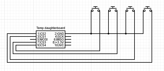
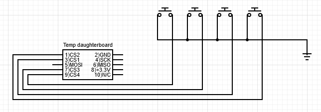
Since the coreXY is my test mule and have future plans on making it into an IDEX, I am attempting to use the temperature daughter board pins 3)CS1, 1)CS2, 7)CS3, 9)CS4 and 2)GND for my external triggers. Using momentary switches SPST-NO with a common ground attached to 2)GND pin.
Can I use 2)GND for my common ground for all the buttons? Are there better pins to use on the Duet Ethernet other than pins 3)CS1, 1)CS2, 7)CS3, 9)CS4 on the temp daughter board and the expansion pins?
My issue is that when a button is pressed it, it basically does an infinite loop of that button's macro until I press the mains switch. Once powered back on, the printer functions as normal until the external button is pressed again.
Once I can fix the infinite loop, Pause and baby stepping button's M581 will have R1 instead of R0.
Config.g
; Configuration file for Duet WiFi (firmware version 3.1.1)
; executed by the firmware on start-up
;
; General preferences
G90                                                ; send absolute coordinates...
M83                                                ; ...but relative extruder moves
M550 P"My CoreXY"                                 ; set printer name
M669 K1                                            ; select CoreXY mode

; Network
M552 P0.0.0.0 S1                                   ; enable network and acquire dynamic address via DHCP
M586 P0 S1                                         ; enable HTTP
M586 P1 S0                                         ; disable FTP
M586 P2 S0                                         ; disable Telnet

; Drives
M569 P0 S1                                         ; physical drive 0 goes forwards
M569 P1 S1                                         ; physical drive 1 goes forwards
M569 P2 S0                                         ; physical drive 2 goes backwards (Z1)
M569 P3 S1                                         ; physical drive 3 goes backwards (extruder)
M569 P4 S0					 					   ; physical drive 4 goes backwards (Z2)
M584 X0 Y1 Z2:4 E3 U4 P3                           ; set drive mapping
M671 X15:305:160 Y15:15:320 P0.5				   ; bed screw locations
M350 X16 Y16 Z16:16 E16 U16 I1                         ; configure microstepping with interpolation
M92 X160.00 Y160.00 Z1600.00:1600.00 U1600.00 E419.00  ; set steps per mm
M566 X1020.00 Y720.00 Z20 U20 E1000.00 P1         	   ; set maximum instantaneous speed changes (mm/min)
M203 X12000.00 Y9600.00 Z240:240 U240.00 E3600.00      ; set maximum speeds (mm/min)
M201 X1500.00 Y1000.00 Z50.00:50.00 U50.00 E2500.00    ; set accelerations (mm/s^2)
M906 X1400 Y1400 Z1100:1100 E1200 U1100 I30            ; set motor currents (mA) and motor idle factor in per cent
M84 S30                                                ; Set idle timeout

; Axis Limits
M208 X0 Y0 Z0 U0 S1                                ; set axis minima
M208 X330 Y315 Z380 U380 S0                        ; set axis maxima

; Endstops
M574 X1 S1 P"!xstop"                                ; configure active-low endstop for low end on X via pin xstop
M574 Y1 S1 P"!ystop"                                ; configure active-low endstop for low end on Y via pin ystop
M574 Z1 S1 P"!zstop+!e1stop" 						; configure active-low endstops for low end on Z via pins zstop and e1stop

; Z-Probe
M558 P0 H4.30 F120 T6000							; manual bed leveling
M557 X15:305:160 Y15:15:320                         ; define mesh grid with G29 for probing

;; ABL inductance sensor
;M558 P5 C"!zprobe.in+zprobe.mod" I1 H5 F120 T6000 A5 R1 S0.10 B0      ; set Z probe type to unmodulated and the dive height + speeds
;G31 P500 X-47 Y-20 Z0.815                          ; set Z probe trigger value, offset and trigger height
;M557 X0:280 Y25:295 P10                            ; define mesh grid

; Heaters
M308 S0 P"bedtemp" Y"thermistor" A"bed" T100000 B3950 R4700    		; configure sensor 0 as thermistor on pin bedtemp
M950 H0 C"bedheat" T0                              ; create bed heater output on bedheat and map it to sensor 0
M140 H0                                            ; map heated bed to heater 0
M143 H0 S105                                       ; set temperature limit for heater 0 to 105C
M307 H0 A89.2 C656.9 D1.7 V24.0 B0 S1.00           ; bed heater and set PWM limit

M308 S1 P"e0temp" Y"thermistor" A"hot end" T100000 B3950 R4700		; configure sensor 1 as thermistor on pin e0temp
M950 H1 C"e0heat" T1 Q100                          ; create nozzle heater output on e0heat and map it to sensor 1
M143 H1 S250                                       ; set temperature limit for heater 1 to 250C
M307 H1 A500.4 C279.3 D5.9 V24.1 S0.5 B0           ; hot end heater and set PWM limit

M308 S2 P"e1temp" Y"thermistor" A"chamber" T100000 B4725 C0.0000000706; configure chamber temp thermister on pin e1temp
M950 H2 C"e1heat" T2 								; chamber heater to heater 2
M141 H2;											; chamber heater called

; Fans
M950 F0 C"fan0" Q22500                             ; create fan 1 on pin fan1 and set its frequency
M106 P0 C"PartsFAN" S0 H-1 B0.2	R1	      	       ; set fan 0 value. Thermostatic control is turned off
M950 F1 C"fan1" Q500                               ; create fan 0 on pin fan0 and set its frequency
M106 P1 C"HotendFAN" S1 H1 T45 R1                  ; set fan 1 value. Thermostatic control is turned on

; Tools
M563 P1 S"hotend" D0 H1 F0                         ; define tool 1
G10 P1 X0 Y0 Z0                                    ; set tool 1 axis offsets
G10 P1 R0 S0                                       ; set initial tool 1 active and standby temperatures to 0C

; Triggers
M950 J1 C"spi.cs1"								; create pin1 for baby step (+)
M581 T2 P1 S1 R0								; create trigger for pin1
;M950 J2 C"spi.cs2"								; create pin2 for baby step (-)
;M581 T3 P2 S1 R0								; create trigger for pin2
;M950 J3 C"spi.cs3"								; create pin3 for emergency stop
;M581 T4 P3 S1 R0								; create stop trigger for pin3
;M950 J4 C"spi.cs4"								; create pin3 for emergency stop
;M581 T5 P4 S1 R0								; create stop trigger for pin4

; Custom settings
M912 S-8										   ; set electronics temperature monitor adjustment
M911 S10 R11 P"M913 X0 Y0 G91 M83 G1 Z3 E-5 F1000" ; set voltage thresholds and actions to run on power loss
M591 C"e0stop" D0 P1 S1                        	   ; Enable E1 Endstop for filament run out detection
M593 F38.25										   ; Configure Dynamic Acceleration Adjustment
M564 H0						  					   ; allow axis movement before homing
;;M572 D0 S0.50									   ; pressure advance

; Miscellaneous
T0                                                 ; select first tool
trigger2.g
; trigger2.g
; baby stepping (+)

M290 R1 S0.01			; increase baby step by 0.01mm
trigger3.g
; trigger3.g
; baby stepping (-)

M290 R1 S-0.01			; increase baby step by 0.01mm