Duet3D Logo Duet3D
    • Tags
    • Documentation
    • Order
    • Register
    • Login

    First Layer and Extrusion Problems

    Scheduled Pinned Locked Moved
    Tuning and tweaking
    6
    121
    5.6k
    Loading More Posts
    • Oldest to Newest
    • Newest to Oldest
    • Most Votes
    Reply
    • Reply as topic
    Log in to reply
    This topic has been deleted. Only users with topic management privileges can see it.
    • fcwiltundefined
      fcwilt @Frederik
      last edited by

      @Frederik said in First Layer and Extrusion Problems:

      @fcwilt you are right, I meant probe. It's all a bit confusing in the beginning 🙂

      I understand which is why I strive to be as clear as I can and not say things that are potentially confusing or abiguous - and yet it still happens.

      Printers: a small Utilmaker style, a small CoreXY and a E3D MS/TC setup. Various hotends. Using Duet 3 hardware running 3.4.6

      1 Reply Last reply Reply Quote 0
      • A Former User?
        A Former User @fcwilt
        last edited by A Former User

        @fcwilt

        Sorry but if you are using x3 leadsrews it would naturally be good practice to be initiating the bed.g file after homing and then applying the correction and after that correction has been applied you would have the head/probe/nozzle RE-Probe in the centre to re-establish the datum before printing commences.

        1 Reply Last reply Reply Quote 0
        • A Former User?
          A Former User
          last edited by A Former User

          For example everything gets done at once

          ; bed.g
          ;
          ; called to perform automatic bed compensation via G32
          ;
          G28                         ; Home all
          G30 P0 X2 Y-2 Z-99999       ; Probe near the front left lead-screw
          G30 P1 X152 Y278 Z-99999    ; Probe near the rear lead screw 
          G30 P2 X290 Y-2 Z-99999 S3  ; Probe near the front right lead-screw
          G30 P0 X2 Y-2 Z-99999       ; Probe near the front left lead-screw (Second Pass)
          G30 P1 X152 Y278 Z-99999    ; Probe near the rear lead screw (Second Pass)
          G30 P2 X290 Y-2 Z-99999 S3  ; Probe near the front right lead-screw (Second Pass) 
          G91                         ; Switch to relative positioning moves
          G1 H2 Z5 F8000              ; Drop the Z axis (the bed) by 5mm relative to its current position
          G90                         ; Revert back to absolute positioning moves
          G1 X160 Y155 F8000          ; Position the nozzle at the centre of the bed
          G30                         ; Probe and set the height as probed
          G29 S1 P"heightmap.csv"     ; Load the height map
          
          
          fcwiltundefined 1 Reply Last reply Reply Quote 0
          • fcwiltundefined
            fcwilt @A Former User
            last edited by

            @CaLviNx said in First Layer and Extrusion Problems:

            For example everything gets done at once

            Yes if you do everything in bed.g you are having the probe point only specified in that one location.

            But not everyone does it that way. I certainly don't.

            My bed.g file only auto-levels the bed and sets the Z=0 datum.

            But there are other times when setting the Z=0 datum is important.

            For example I have more than one height map that is loaded depending on the state of a fan name that I am current using in lieu of variables.

            The macro that loads the height map uses a few others macros. One configures the probe, one positions the probe to bed center, one does the probing.

            To position the probe to bed center I don't have to remember the correct XY values I simply call the macro and it does the math and positions the probe.

            Frederick

            Printers: a small Utilmaker style, a small CoreXY and a E3D MS/TC setup. Various hotends. Using Duet 3 hardware running 3.4.6

            A Former User? 1 Reply Last reply Reply Quote 0
            • A Former User?
              A Former User @fcwilt
              last edited by

              @fcwilt

              so does that one above......................

              fcwiltundefined 1 Reply Last reply Reply Quote 0
              • fcwiltundefined
                fcwilt @A Former User
                last edited by

                @CaLviNx said in First Layer and Extrusion Problems:

                @fcwilt

                so does that one above......................

                But if you have to set the Z=0 datum somewhere else you have to remember to use those same values.

                Frederick

                Printers: a small Utilmaker style, a small CoreXY and a E3D MS/TC setup. Various hotends. Using Duet 3 hardware running 3.4.6

                A Former User? 1 Reply Last reply Reply Quote 0
                • Frederikundefined
                  Frederik
                  last edited by

                  so i hope i changed everything accordingly.

                  after i run a mesh i got this hightmap

                  2020-11-20_22h08_05.png

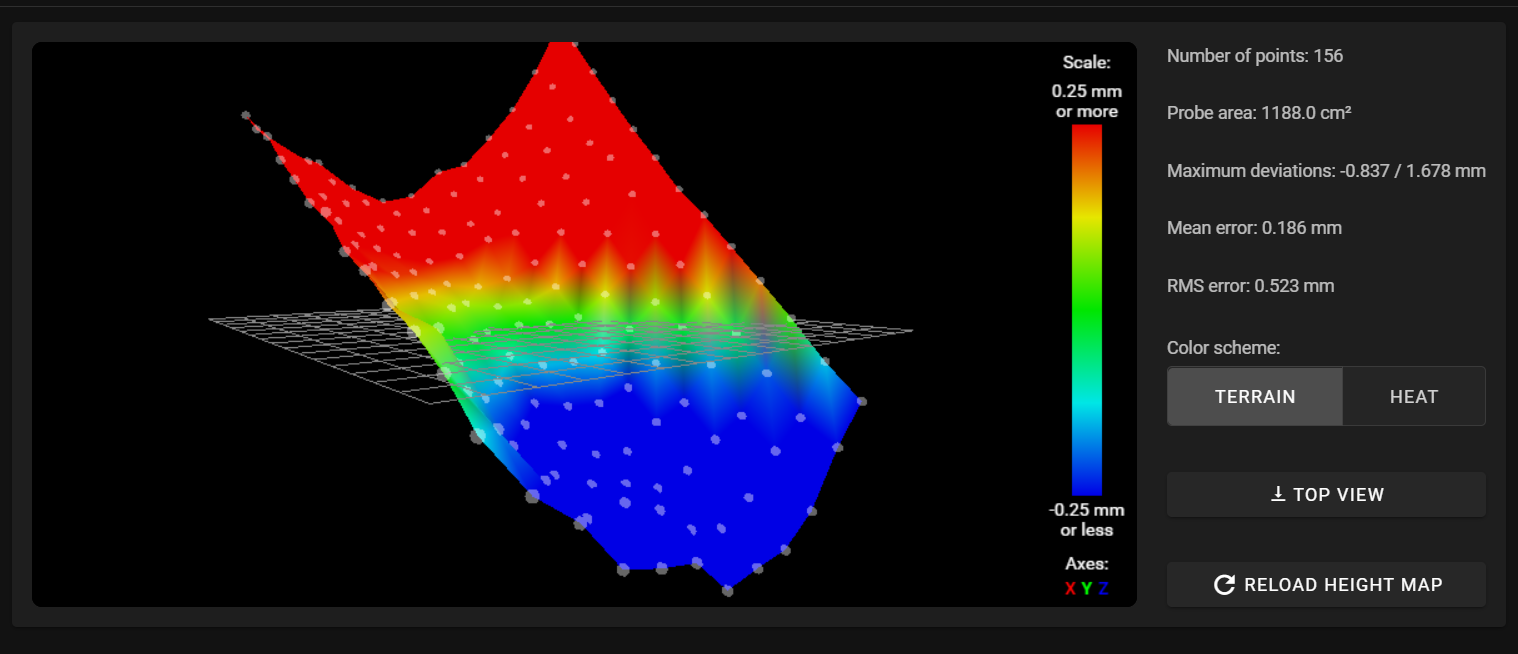
                  and this the consol putput:

                  20.11.2020, 22:08:00	G32
                  Leadscrew adjustments made: 0.283 0.880 0.293, points used 3, (mean, deviation) before (0.453, 0.263) after (-0.000, 0.000)
                  Leadscrew adjustments made: -0.044 0.333 -0.061, points used 3, (mean, deviation) before (0.053, 0.172) after (-0.000, 0.000)
                  Height map loaded from file heightmap.csv
                  20.11.2020, 22:05:43	G29
                  156 points probed, min error -0.837, max error 1.678, mean 0.186, deviation 0.523
                  Height map saved to file heightmap.csv
                  
                  A Former User? 1 Reply Last reply Reply Quote 0
                  • A Former User?
                    A Former User @fcwilt
                    last edited by

                    @fcwilt said in First Layer and Extrusion Problems:

                    But if you have to set the Z=0 datum somewhere else you have to remember to use those same values.

                    Frederick

                    why would a beginner (as it was you that put the beginner thing out there) require to be going down the route of setting a Z=0 elsewhere ?

                    1 Reply Last reply Reply Quote 0
                    • A Former User?
                      A Former User @Frederik
                      last edited by A Former User

                      @Frederik

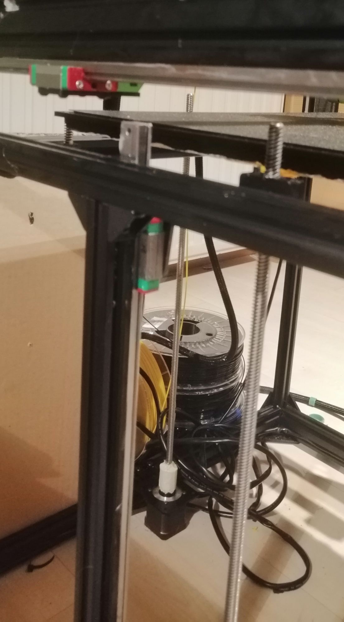
                      do you have a picture of your setup ? (as in the printer itself)

                      Frederikundefined 1 Reply Last reply Reply Quote 0
                      • Frederikundefined
                        Frederik @A Former User
                        last edited by

                        @CaLviNx IMG_20201120_221537.jpg IMG_20201120_221704.jpg IMG_20201120_221621.jpg

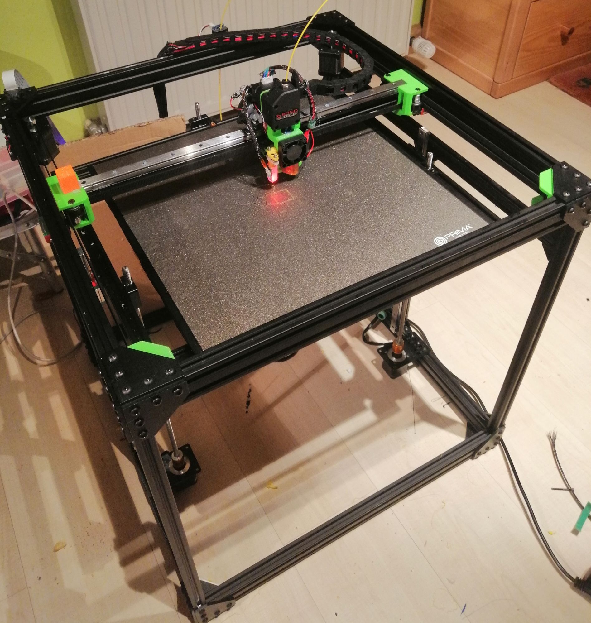
                        My Printer is a Ratrig VCore Pro Kit with the EasyMod and EVA Carriage.

                        I startet my journey into 3d printing around 4 weeks ago with Information gathering etc...
                        ... And 4 days ago, I finished the build.

                        A Former User? 1 Reply Last reply Reply Quote 0
                        • A Former User?
                          A Former User @Frederik
                          last edited by A Former User

                          @Frederik

                          if it was me I would firstly tension the bed to bed frame springs, then measure them and make they all the same height, perpendicular to the bed frame.

                          Then I would home all with the final homing of Z axis taking place with the probe located at the bed centre.

                          Then I would have the printer carry out a G32 (more than once) NOTHING else, and allow it to "level" the bed/frame using the three lead screws, and allow it to apply those corrections .

                          Then carry out a single G30 probing at the centre of the bed to re-establish the datum point.

                          Then finally carry out a G29 and see what it comes up with.

                          You need to remember level doesnt mean flat..... and dont get too hung up on the graphic look at the amount of deviation you have.

                          how many linear rails does the z axis run on ?

                          Frederikundefined 1 Reply Last reply Reply Quote 0
                          • Frederikundefined
                            Frederik @A Former User
                            last edited by

                            @CaLviNx Ok, i will test this in the morning.

                            I have 2 Linear Rails on z ( left + right in the middle ). The Leadscrews are ~ 6 cm in front of them

                            A Former User? 1 Reply Last reply Reply Quote 0
                            • A Former User?
                              A Former User @Frederik
                              last edited by

                              @Frederik said in First Layer and Extrusion Problems:

                              I have 2 Linear Rails on z ( left + right in the middle ). The Leadscrews are ~ 6 cm in front of them

                              A very strange (to me anyway) arrangement for linear rails, in that you would expect 3 rails with three lead screws.

                              But if it works then happy days. Personally I always have x3 rails/lead screws and have the bed frame with a degree of articulation to allow the levelling to operate as it should, once you get it setup the levelling gives you great prints

                              Frederikundefined 1 Reply Last reply Reply Quote 0
                              • Vetiundefined
                                Veti
                                last edited by

                                @CaLviNx said in First Layer and Extrusion Problems:

                                G30 P0 X2 Y-2 Z-99999 ; Probe near the front left lead-screw

                                G30 P1 X152 Y278 Z-99999 ; Probe near the rear lead screw

                                G30 P2 X290 Y-2 Z-99999 S3 ; Probe near the front right lead-screw

                                M671 X425:200:-25 Y240:-25:240 S1 ; leadscrews at front left, rear middle and front right

                                how are these points near the leadscrews?

                                Frederikundefined 1 Reply Last reply Reply Quote 0
                                • Frederikundefined
                                  Frederik @A Former User
                                  last edited by

                                  @CaLviNx That´s how this kit is designed. Eventually, I will change it to a kinematic mount without the 2 Linear Rails like the HevOrt. At the moment I have a battle with my E3d Volcano... it is constantly clogging and I don´t know what
                                  I´m doing wrong... trying to print PLA with ~ 205 ° Nozzle and 60° Bed.

                                  1 Reply Last reply Reply Quote 0
                                  • Frederikundefined
                                    Frederik @Veti
                                    last edited by

                                    @Veti i have this settings:

                                    M671 X425:200:-25 Y240:-25:240 S3 - position of Spindles with drives 2.3.4

                                    and this are the spot i´m probing:

                                    G30 P0 X330 Y250 Z-99999 ; Probe near the front left lead-screw
                                    G30 P1 X165 Y0 Z-99999 ; Probe near the rear lead screw
                                    G30 P2 X0 Y250 Z-99999 S3 ; Probe near the front right lead-screw

                                    1 Reply Last reply Reply Quote 0
                                    • Vetiundefined
                                      Veti
                                      last edited by

                                      is 0,0 not the bottom left of your printbed?

                                      Frederikundefined 1 Reply Last reply Reply Quote 0
                                      • Frederikundefined
                                        Frederik @Veti
                                        last edited by

                                        @Veti x0,y0 ls in my case the right, rear corner

                                        Vetiundefined 1 Reply Last reply Reply Quote 0
                                        • Frederikundefined
                                          Frederik
                                          last edited by

                                          I could only mount the Endstop on the left side of my carriage and the Y Endstop is at the back

                                          fcwiltundefined 1 Reply Last reply Reply Quote 0
                                          • Vetiundefined
                                            Veti @Frederik
                                            last edited by

                                            @Frederik said in First Layer and Extrusion Problems:

                                            x0,y0 ls in my case the right, rear corner

                                            thats going to be very confusing.
                                            certainly because of that you got the offset of your probe wrong.

                                            Frederikundefined 2 Replies Last reply Reply Quote 0
                                            • First post
                                              Last post
                                            Unless otherwise noted, all forum content is licensed under CC-BY-SA