Confused on wiring for Ender 3 Pro Conversion
-
hi
please dont connect the usb while other power is connected.
see https://duet3d.dozuki.com/Wiki/USB_ground_loopshave you read this guide?
https://duet3d.dozuki.com/Guide/Ender+3+Pro+and+Duet+Maestro+Guide+Part+1:+Wiring/37the config tool is here
https://configtool.reprapfirmware.org/Start -
When ever I connect by USB, I have the power supply cable unplugged from it. I'll check out the guide again and see what it says. Thanks.
EDIT And this is the guide I have already been using.
-
This post is deleted! -
if you set a password its in the config.g that you generated
i.e
M551 P"test" ; set password
-
@Veti Yeah, I went back and set an actual password. Thank you.
-
Now when I start the E3P and everything works fine except I get "ERROR: Temperature reading fault on heater 1: open circuit" I followed all the steps in the setup guide you have linked above. Though the configurator is different than in the guide, it's still pretty straight forward.
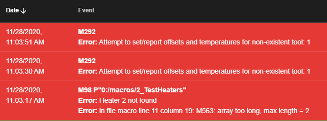
Current temp is showing -273.1c. And when I go to test the heaters, it throws off a bunch of errors and nothing heats up.
-
what is this test heater macro? that seems to test a second heater that you did not configure.
Current temp is showing -273.1
this means that your thermistor is shorted out and has no resistance. check the wiring.
-
@Veti I'm using the Test button that's on the web interface and also on the 7i when I'm looking at that panel. I cut and termed the wires with the pins and connectors for the Duet board. When I copied over from diagram to diagram, it showed the same error. Switched the 2 wires thinking that I may have read it wrong, same error.
-
@Destruct0Dan said in Confused on wiring for Ender 3 Pro Conversion:
I'm using the Test button that's on the web interface and also on the 7i when I'm looking at that panel.
the macro is certainly not for your printer and does not work.
check the wire with a multimeter.
-
@Veti Well, guess I have to wait for that to come in. Don't have one. Once I get this, how do I need to test to make sure everything is okay?
-
does the bed temperature work?
-
@Destruct0Dan FYI, the 'test_xxx' macros (that you're seeing) are the ones that come on the SD card from the factory. They are the end of line tests that Duet3d run with their test setup to check the board, so won't work for your setup. Recommendation is to delete them
")
E3D TC with D3Mini and Toolboards.
Home-built CoreXY, Duet Wifi, Chimera direct drive, 2x BMG, 300x300x300 build volume
i3 clone with a bunch of mods -
@Veti No, bed temp won't turn on either.
-
@engikeneer Ah okay, thanks. How can I or how do I remove those?
-
@Destruct0Dan via the web control, go to macros to find them, right click and delete.
Otherwise, put the sd card in your PC and delete them.
Might be a way through Paneldue, but I don't have one so wouldn't know how... -
@engikeneer said in Confused on wiring for Ender 3 Pro Conversion:
Might be a way through Paneldue, but I don't have one so wouldn't know how...
Nope.
@Destruct0Dan When you first turn the printer on what do the heater temps report?
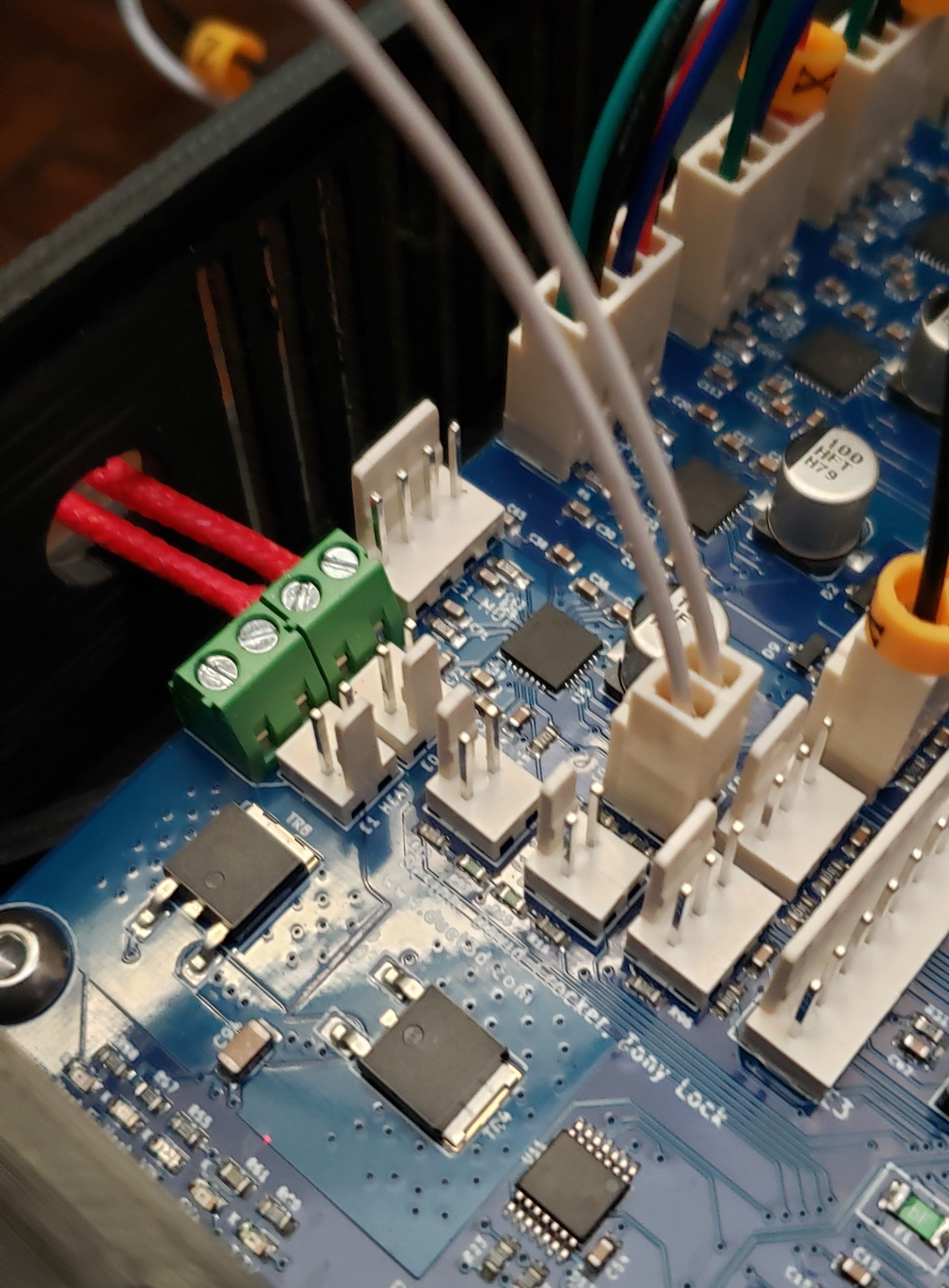
Can you post a picture of how you have the thermistor and heater wires connected on the board?
Also post your config.g and the results of sending M122 and M98 P"config.g"
-
-
-
This post is deleted! -
; Configuration file for Duet Maestro (firmware version 3)
; executed by the firmware on start-up
;
; generated by RepRapFirmware Configuration Tool v3.1.9 on Sat Nov 28 2020 10:13:54 GMT-0800 (Pacific Standard Time); General preferences
G90 ; send absolute coordinates...
M83 ; ...but relative extruder moves
M550 P"Ender3ProMaestro2" ; set printer name
M918 P1 E4 F2000000 ; configure direct-connect display; Network
M551 P"REDACTED" ; set password
M552 P192.168.1.23 S1 ; enable network and set IP address
M553 P255.255.255.0 ; set netmask
M554 P192.168.1.254 ; set gateway
M586 P0 S1 ; enable HTTP
M586 P1 S0 ; disable FTP
M586 P2 S0 ; disable Telnet; Drives
M569 P0 S0 ; physical drive 0 goes backwards
M569 P1 S0 ; physical drive 1 goes backwards
M569 P2 S1 ; physical drive 2 goes forwards
M569 P3 S0 ; physical drive 3 goes backwards
M584 X0 Y1 Z2 E3 ; set drive mapping
M350 X16 Y16 Z16 E16 I1 ; configure microstepping with interpolation
M92 X80.00 Y80.00 Z400.00 E93.00 ; set steps per mm
M566 X600.00 Y600.00 Z60.00 E300.00 ; set maximum instantaneous speed changes (mm/min)
M203 X9000.00 Y9000.00 Z600.00 E6000.00 ; set maximum speeds (mm/min)
M201 X500.00 Y500.00 Z120.00 E5000.00 ; set accelerations (mm/s^2)
M906 X800 Y800 Z800 E900 I30 ; set motor currents (mA) and motor idle factor in per cent
M84 S30 ; Set idle timeout; Axis Limits
M208 X0 Y0 Z0 S1 ; set axis minima
M208 X235 Y235 Z260 S0 ; set axis maxima; Endstops
M574 X1 S1 P"xstop" ; configure active-high endstop for low end on X via pin xstop
M574 Y1 S1 P"ystop" ; configure active-high endstop for low end on Y via pin ystop
M574 Z1 S1 P"zstop" ; configure active-high endstop for low end on Z via pin zstop; Z-Probe
M558 P0 H5 F120 T6000 ; disable Z probe but set dive height, probe speed and travel speed
M557 X10:220 Y10:220 S20 ; define mesh grid; Heaters
M308 S0 P"bedtemp" Y"thermistor" T9880 B4185 ; configure sensor 0 as thermistor on pin bedtemp
M950 H0 C"bedheat" T0 ; create bed heater output on bedheat and map it to sensor 0
M307 H0 B0 S1.00 ; disable bang-bang mode for the bed heater and set PWM limit
M140 H0 ; map heated bed to heater 0
M143 H0 S80 ; set temperature limit for heater 0 to 80C
M308 S1 P"e0temp" Y"thermistor" T9880 B4185 ; configure sensor 1 as thermistor on pin e0temp
M950 H1 C"e0heat" T1 ; create nozzle heater output on e0heat and map it to sensor 1
M307 H1 B0 S1.00 ; disable bang-bang mode for heater and set PWM limit
M143 H1 S250 ; set temperature limit for heater 1 to 250C; Fans
M950 F0 C"fan0" Q20 ; create fan 0 on pin fan0 and set its frequency
M106 P0 S0 H-1 ; set fan 0 value. Thermostatic control is turned off
M950 F1 C"fan1" Q500 ; create fan 1 on pin fan1 and set its frequency
M106 P1 S0 H1 T45 ; set fan 1 value. Thermostatic control is turned on
M950 F2 C"fan2" Q500 ; create fan 2 on pin fan2 and set its frequency
M106 P2 S0 H1:0 T45 ; set fan 2 value. Thermostatic control is turned on; Tools
M563 P0 S"HotEnd" D0 H1 F0:1:2 ; define tool 0
G10 P0 X0 Y0 Z0 ; set tool 0 axis offsets
G10 P0 R0 S0 ; set initial tool 0 active and standby temperatures to 0C; Custom settings
M575 P1 S1 B57600 ; enable support for PanelDue; Miscellaneous
M575 P1 S1 B57600 ; enable support for PanelDue
M501 ; load saved parameters from non-volatile memory
M911 S21 R23 P"M913 X0 Y0 G91 M83 G1 Z3 E-5 F1000" ; set voltage thresholds and actions to run on power loss
T0 ; select first tool