Duet3D Logo Duet3D
    • Tags
    • Documentation
    • Order
    • Register
    • Login

    Confused on wiring for Ender 3 Pro Conversion

    Scheduled Pinned Locked Moved
    Duet Hardware and wiring
    5
    50
    1.8k
    Loading More Posts
    • Oldest to Newest
    • Newest to Oldest
    • Most Votes
    Reply
    • Reply as topic
    Log in to reply
    This topic has been deleted. Only users with topic management privileges can see it.
    • Destruct0Danundefined
      Destruct0Dan
      last edited by

      From the M122:

      M122
      === Diagnostics ===
      RepRapFirmware for Duet 2 Maestro version 3.1.1 running on Duet Maestro 1.0
      Board ID: 08DLM-9T6R1-MA3TN-6JKD4-3SW6J-KFZKP
      Used output buffers: 3 of 24 (10 max)
      === RTOS ===
      Static ram: 21924
      Dynamic ram: 93124 of which 32 recycled
      Exception stack ram used: 176
      Never used ram: 15816
      Tasks: NETWORK(ready,472) HEAT(blocked,548) MAIN(running,1996) IDLE(ready,84)
      Owned mutexes:
      === Platform ===
      Last reset 00:01:23 ago, cause: power up
      Last software reset time unknown, reason: User, spinning module GCodes, available RAM 19672 bytes (slot 3)
      Software reset code 0x0003 HFSR 0x00000000 CFSR 0x00000000 ICSR 0x0400f000 BFAR 0xe000ed38 SP 0xffffffff Task MAIN
      Error status: 0
      MCU temperature: min 23.6, current 30.1, max 30.2
      Supply voltage: min 0.0, current 24.1, max 24.2, under voltage events: 0, over voltage events: 0, power good: yes
      Driver 0: standstill, read errors 0, write errors 0, ifcount 7, reads 3338, timeouts 0
      Driver 1: standstill, read errors 0, write errors 0, ifcount 7, reads 3338, timeouts 0
      Driver 2: standstill, read errors 0, write errors 0, ifcount 7, reads 3338, timeouts 0
      Driver 3: standstill, read errors 0, write errors 0, ifcount 7, reads 3338, timeouts 0
      Driver 4: standstill, read errors 0, write errors 0, ifcount 6, reads 3339, timeouts 0
      Driver 5: ok, read errors 0, write errors 0, ifcount 0, reads 0, timeouts 3345
      Driver 6: ok, read errors 0, write errors 0, ifcount 0, reads 0, timeouts 3344
      Date/time: 2020-11-28 14:20:09
      Slowest loop: 3.01ms; fastest: 0.14ms
      I2C nak errors 0, send timeouts 0, receive timeouts 0, finishTimeouts 0, resets 0
      === Storage ===
      Free file entries: 10
      SD card 0 detected, interface speed: 15.0MBytes/sec
      SD card longest read time 0.7ms, write time 0.0ms, max retries 0
      === Move ===
      Hiccups: 0(0), FreeDm: 169, MinFreeDm: 169, MaxWait: 0ms
      Bed compensation in use: none, comp offset 0.000
      === MainDDARing ===
      Scheduled moves: 0, completed moves: 0, StepErrors: 0, LaErrors: 0, Underruns: 0, 0 CDDA state: -1
      === AuxDDARing ===
      Scheduled moves: 0, completed moves: 0, StepErrors: 0, LaErrors: 0, Underruns: 0, 0 CDDA state: -1
      === Heat ===
      Bed heaters = 0 -1, chamberHeaters = -1 -1
      === GCodes ===
      Segments left: 0
      Movement lock held by null
      HTTP is idle in state(s) 0
      Telnet is idle in state(s) 0
      File is idle in state(s) 0
      USB is idle in state(s) 0
      Aux is idle in state(s) 0
      Trigger is idle in state(s) 0
      Queue is idle in state(s) 0
      LCD is idle in state(s) 0
      Daemon is idle in state(s) 0
      Autopause is idle in state(s) 0
      Code queue is empty.
      === Network ===
      Slowest loop: 56.41ms; fastest: 0.02ms
      Responder states: HTTP(0) HTTP(0) HTTP(0) HTTP(0) FTP(0) Telnet(0), 0 sessions
      HTTP sessions: 1 of 8
      Interface state active, link 100Mbps full duplex

      1 Reply Last reply Reply Quote 0
      • Destruct0Danundefined
        Destruct0Dan
        last edited by

        And then with the last request:

        885ec43d-47cd-4a58-9228-6865c3aa59ad-image.png

        1 Reply Last reply Reply Quote 0
        • Phaedruxundefined
          Phaedrux Moderator
          last edited by

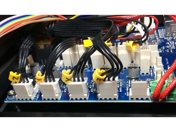
          Your thermistor isn't plugged into the E0 Thermistor port.

          It should be in the one right next to the heater terminals.

          Z-Bot CoreXY Build | Thingiverse Profile

          Destruct0Danundefined 1 Reply Last reply Reply Quote 0
          • Destruct0Danundefined
            Destruct0Dan @Phaedrux
            last edited by

            @Phaedrux That's what I fugured. But going off of this picture from your install guide, I plugged it into the same connector shown.

            78389a53-58ce-4497-9a3c-2ae4a661f64f-image.png

            Now switching ports on the board has not changed anything with the temp shown on the 7i. It still shows a -273.1 temp still. Do I need to do a Reset Heater Fault and see what happens?

            1 Reply Last reply Reply Quote 0
            • Phaedruxundefined
              Phaedrux Moderator
              last edited by

              I knew that picture would come back to haunt me. 🙂

              You'd need to power cycle the board.

              Z-Bot CoreXY Build | Thingiverse Profile

              Destruct0Danundefined 1 Reply Last reply Reply Quote 0
              • Destruct0Danundefined
                Destruct0Dan @Phaedrux
                last edited by

                @Phaedrux lol No worries. I was just trying to stick to what's laid out. Now I have powered down and powered back up the board. Every time I disconnect and reconnect cables I unplug the PSU cable. Still ends up saying the same thing.

                1 Reply Last reply Reply Quote 0
                • Destruct0Danundefined
                  Destruct0Dan
                  last edited by

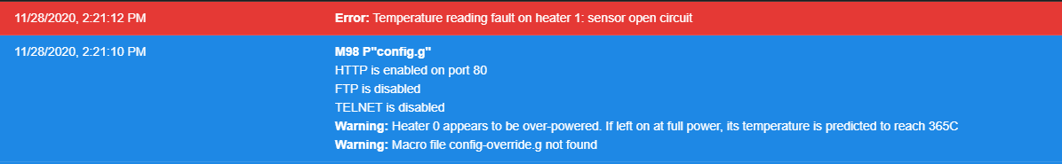
                  Still doing this after fully power cycling the printer.

                  update2 (2).jpg update1 (2).jpg

                  1 Reply Last reply Reply Quote 0
                  • Phaedruxundefined
                    Phaedrux Moderator
                    last edited by

                    It's showing open circuit on both your heaters. Are the wires actually connected? Bad crimp?

                    Z-Bot CoreXY Build | Thingiverse Profile

                    1 Reply Last reply Reply Quote 0
                    • Destruct0Danundefined
                      Destruct0Dan
                      last edited by

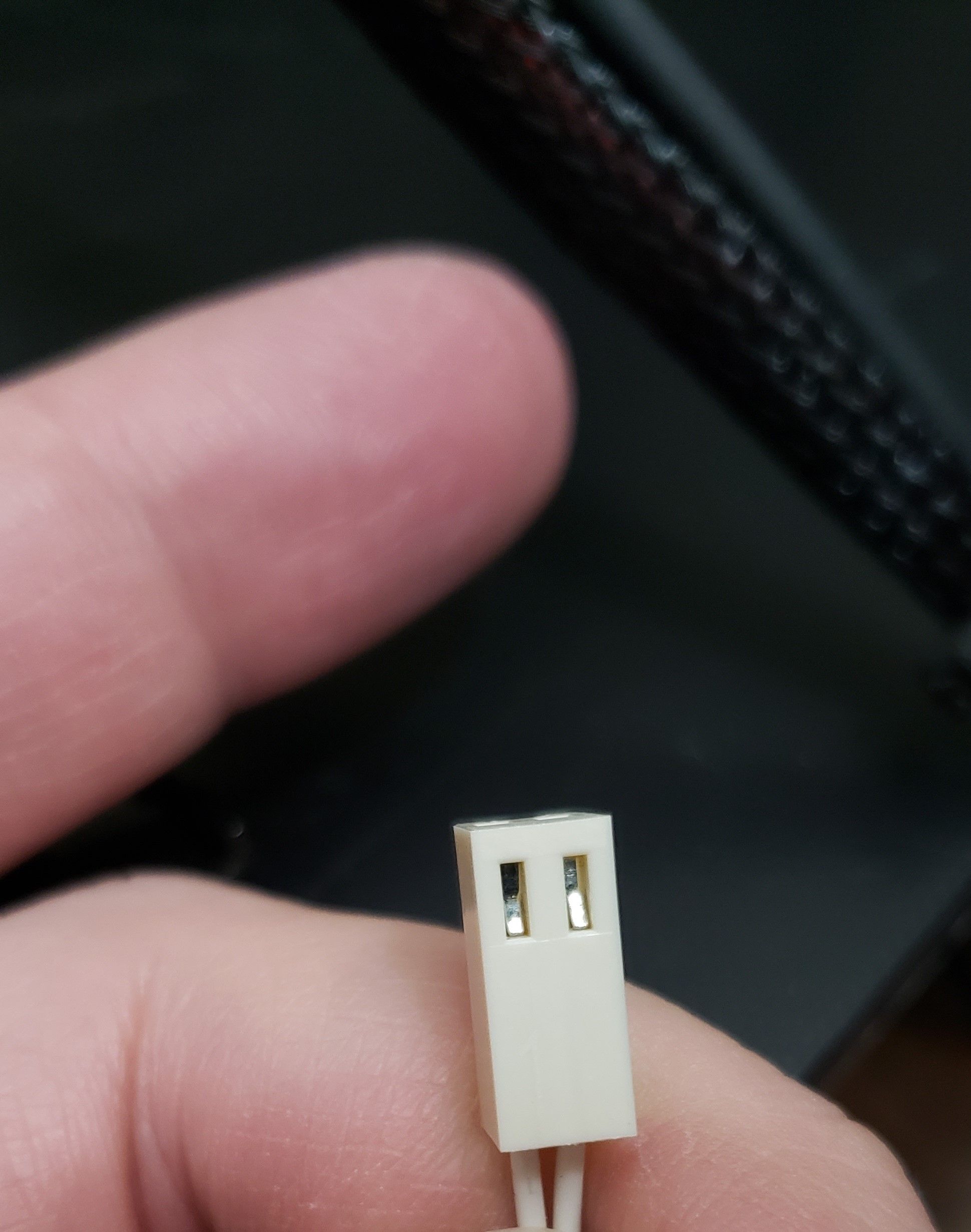
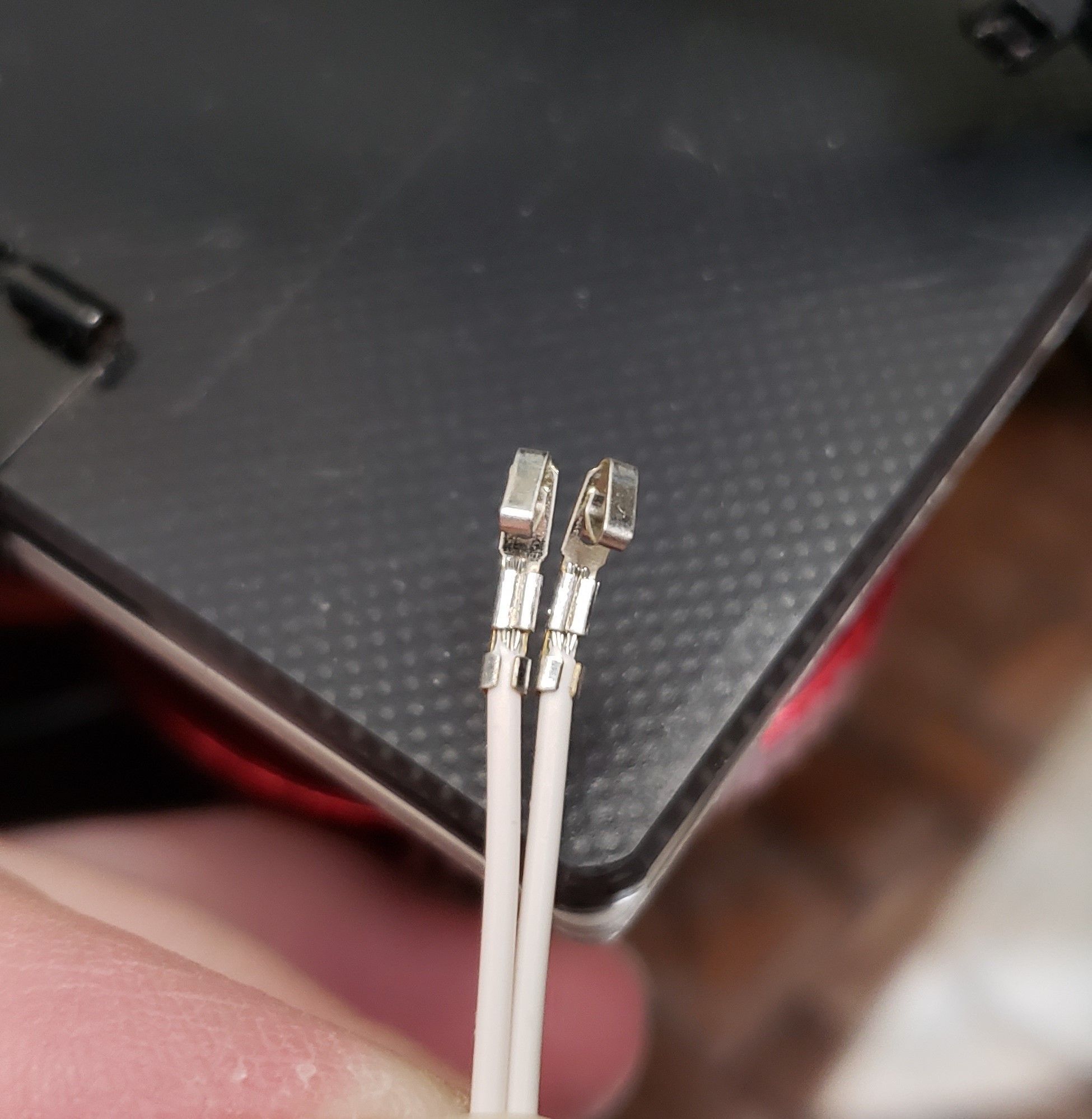
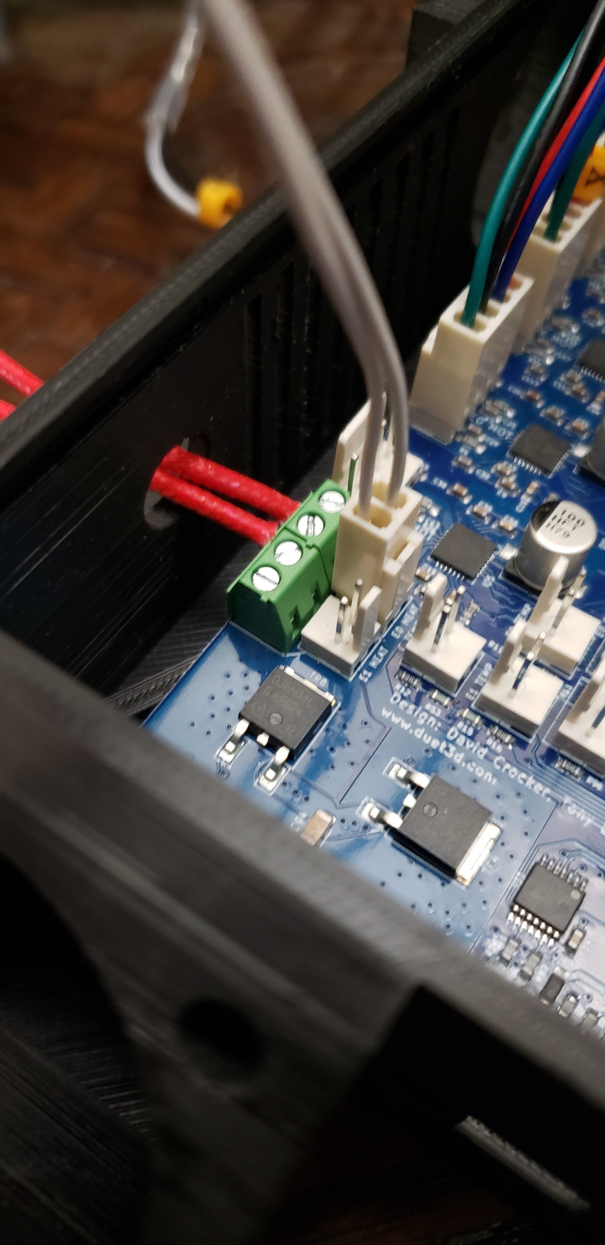
                      Not my best but not my worst. Pins are seated properly too.20201128_192147 (2).jpg 20201128_191939 (2).jpg

                      1 Reply Last reply Reply Quote 0
                      • Destruct0Danundefined
                        Destruct0Dan
                        last edited by

                        Just to verify
                        20201128_192632 (2).jpg

                        1 Reply Last reply Reply Quote 0
                        • A Former User?
                          A Former User
                          last edited by

                          Last picture show the thermistor connected in parallel with the heater element.

                          The two pin header labeled E0 Temp is probably the one you wanted to use. It would help to measure the resistance across the two wires coming from the thermistor if it doesn't work on the correct input to see if the sensor/wiring is okay or not. I guess if subjected to Vin for some time it might not survive due to the heat generated as the resistance drops with increasing temperature.

                          Destruct0Danundefined 1 Reply Last reply Reply Quote 0
                          • Destruct0Danundefined
                            Destruct0Dan @A Former User
                            last edited by

                            @bearer Further up you'll see that it was mentioned for me to move the Therm to this connector. I did originally have it connected to E0 TEMP.

                            1 Reply Last reply Reply Quote 0
                            • Phaedruxundefined
                              Phaedrux Moderator
                              last edited by

                              Maybe I fixed the photo cause I had made the same mistake originally. Will look closer tomorrow after sleep.

                              Z-Bot CoreXY Build | Thingiverse Profile

                              Destruct0Danundefined 1 Reply Last reply Reply Quote 0
                              • A Former User?
                                A Former User
                                last edited by

                                If you have a multimeter try to measure the resistance of the sensor to see if its wired correctly. Disconnect the plug and measure on the crimps in the plug, with thin enough probes you don't even have to remove the crimps from the plug. You should most likely measure around 100k ohm at room temp (20C).

                                1 Reply Last reply Reply Quote 0
                                • Destruct0Danundefined
                                  Destruct0Dan @Phaedrux
                                  last edited by

                                  @Phaedrux Well, just now moved it to that other set I originally had it on and still the same thing.

                                  1 Reply Last reply Reply Quote 0
                                  • Vetiundefined
                                    Veti @Destruct0Dan
                                    last edited by

                                    @Destruct0Dan said in Confused on wiring for Ender 3 Pro Conversion:

                                    M308 S0 P"bedtemp" Y"thermistor" T9880 B4185 ; configure sensor 0 as thermistor on pin bedtemp
                                    M308 S1 P"e0temp" Y"thermistor" T9880 B4185 ; configure sensor 1 as thermistor on pin e0temp

                                    you mistyped your resistance value its 98801

                                    Destruct0Danundefined 1 Reply Last reply Reply Quote 1
                                    • Destruct0Danundefined
                                      Destruct0Dan @Veti
                                      last edited by

                                      @Veti Ah thank you. I take it I need to go through the configurator again to fix that?

                                      Vetiundefined 1 Reply Last reply Reply Quote 0
                                      • Vetiundefined
                                        Veti @Destruct0Dan
                                        last edited by

                                        @Destruct0Dan

                                        no on the duet web ui you can edit the file directly. go to system and click on config.g

                                        Destruct0Danundefined 1 Reply Last reply Reply Quote 0
                                        • Destruct0Danundefined
                                          Destruct0Dan @Veti
                                          last edited by

                                          @Veti added the 1 to both lines that was missing it. Restarted and now to see what it says. Thank you for pointing that out. I had gone through that process a couple times and thought I entered the one like needed. Guess not.

                                          Now my temps are reading the way they should. Now just continue through the setup process from the config setup portion? Also, does it mention where or how to adjust for using a TH3D EZABL Pro for my Z axis?

                                          Vetiundefined 1 Reply Last reply Reply Quote 0
                                          • Vetiundefined
                                            Veti @Destruct0Dan
                                            last edited by

                                            @Destruct0Dan said in Confused on wiring for Ender 3 Pro Conversion:

                                            Also, does it mention where or how to adjust for using a TH3D EZABL Pro for my Z axis?

                                            according to this
                                            https://forum.duet3d.com/topic/4671/rewire-ezabl-capacitive-npn-z-probe-kit-for-duet
                                            its a npn sensor

                                            for wiring see

                                            https://duet3d.dozuki.com/Wiki/Connecting_a_Z_probe#Section_NPN_output_normally_open_inductive_or_capacitive_sensor

                                            Destruct0Danundefined 1 Reply Last reply Reply Quote 0
                                            • First post
                                              Last post
                                            Unless otherwise noted, all forum content is licensed under CC-BY-SA