Duet3D Logo Duet3D
    • Tags
    • Documentation
    • Order
    • Register
    • Login

    Confused on wiring for Ender 3 Pro Conversion

    Scheduled Pinned Locked Moved
    Duet Hardware and wiring
    5
    50
    1.8k
    Loading More Posts
    • Oldest to Newest
    • Newest to Oldest
    • Most Votes
    Reply
    • Reply as topic
    Log in to reply
    This topic has been deleted. Only users with topic management privileges can see it.
    • engikeneerundefined
      engikeneer @Destruct0Dan
      last edited by

      @Destruct0Dan FYI, the 'test_xxx' macros (that you're seeing) are the ones that come on the SD card from the factory. They are the end of line tests that Duet3d run with their test setup to check the board, so won't work for your setup. Recommendation is to delete them 🙂

      E3D TC with D3Mini and Toolboards.
      Home-built CoreXY, Duet Wifi, Chimera direct drive, 2x BMG, 300x300x300 build volume
      i3 clone with a bunch of mods

      Destruct0Danundefined 1 Reply Last reply Reply Quote 1
      • Destruct0Danundefined
        Destruct0Dan @Veti
        last edited by

        @Veti No, bed temp won't turn on either.

        1 Reply Last reply Reply Quote 0
        • Destruct0Danundefined
          Destruct0Dan @engikeneer
          last edited by

          @engikeneer Ah okay, thanks. How can I or how do I remove those?

          engikeneerundefined 1 Reply Last reply Reply Quote 0
          • engikeneerundefined
            engikeneer @Destruct0Dan
            last edited by

            @Destruct0Dan via the web control, go to macros to find them, right click and delete.
            Otherwise, put the sd card in your PC and delete them.
            Might be a way through Paneldue, but I don't have one so wouldn't know how...

            E3D TC with D3Mini and Toolboards.
            Home-built CoreXY, Duet Wifi, Chimera direct drive, 2x BMG, 300x300x300 build volume
            i3 clone with a bunch of mods

            Phaedruxundefined 1 Reply Last reply Reply Quote 0
            • Phaedruxundefined
              Phaedrux Moderator @engikeneer
              last edited by

              @engikeneer said in Confused on wiring for Ender 3 Pro Conversion:

              Might be a way through Paneldue, but I don't have one so wouldn't know how...

              Nope.

              @Destruct0Dan When you first turn the printer on what do the heater temps report?

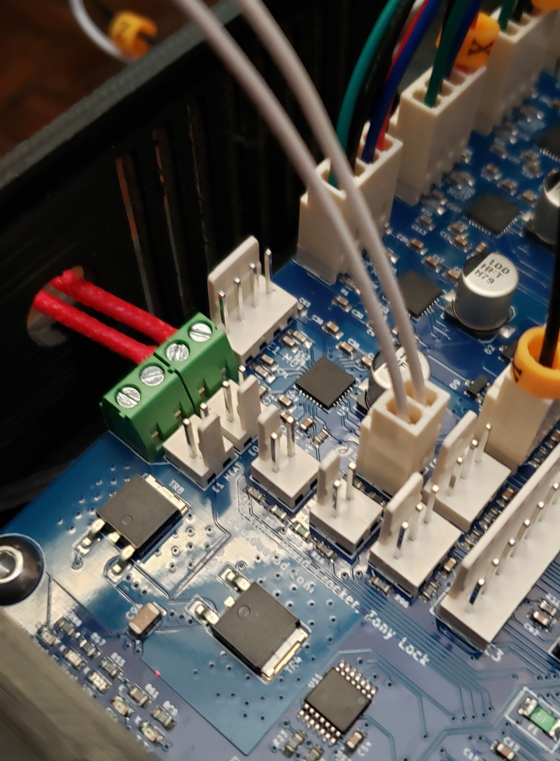
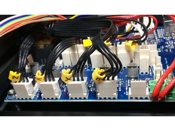
              Can you post a picture of how you have the thermistor and heater wires connected on the board?

              Also post your config.g and the results of sending M122 and M98 P"config.g"

              Z-Bot CoreXY Build | Thingiverse Profile

              Destruct0Danundefined 2 Replies Last reply Reply Quote 0
              • Destruct0Danundefined
                Destruct0Dan @Phaedrux
                last edited by

                @Phaedrux temps (2).jpg

                1 Reply Last reply Reply Quote 0
                • Destruct0Danundefined
                  Destruct0Dan @Phaedrux
                  last edited by

                  @Phaedrux wires (2).jpg

                  1 Reply Last reply Reply Quote 0
                  • Destruct0Danundefined
                    Destruct0Dan
                    last edited by Destruct0Dan

                    This post is deleted!
                    1 Reply Last reply Reply Quote 0
                    • Destruct0Danundefined
                      Destruct0Dan
                      last edited by

                      ; Configuration file for Duet Maestro (firmware version 3)
                      ; executed by the firmware on start-up
                      ;
                      ; generated by RepRapFirmware Configuration Tool v3.1.9 on Sat Nov 28 2020 10:13:54 GMT-0800 (Pacific Standard Time)

                      ; General preferences
                      G90 ; send absolute coordinates...
                      M83 ; ...but relative extruder moves
                      M550 P"Ender3ProMaestro2" ; set printer name
                      M918 P1 E4 F2000000 ; configure direct-connect display

                      ; Network
                      M551 P"REDACTED" ; set password
                      M552 P192.168.1.23 S1 ; enable network and set IP address
                      M553 P255.255.255.0 ; set netmask
                      M554 P192.168.1.254 ; set gateway
                      M586 P0 S1 ; enable HTTP
                      M586 P1 S0 ; disable FTP
                      M586 P2 S0 ; disable Telnet

                      ; Drives
                      M569 P0 S0 ; physical drive 0 goes backwards
                      M569 P1 S0 ; physical drive 1 goes backwards
                      M569 P2 S1 ; physical drive 2 goes forwards
                      M569 P3 S0 ; physical drive 3 goes backwards
                      M584 X0 Y1 Z2 E3 ; set drive mapping
                      M350 X16 Y16 Z16 E16 I1 ; configure microstepping with interpolation
                      M92 X80.00 Y80.00 Z400.00 E93.00 ; set steps per mm
                      M566 X600.00 Y600.00 Z60.00 E300.00 ; set maximum instantaneous speed changes (mm/min)
                      M203 X9000.00 Y9000.00 Z600.00 E6000.00 ; set maximum speeds (mm/min)
                      M201 X500.00 Y500.00 Z120.00 E5000.00 ; set accelerations (mm/s^2)
                      M906 X800 Y800 Z800 E900 I30 ; set motor currents (mA) and motor idle factor in per cent
                      M84 S30 ; Set idle timeout

                      ; Axis Limits
                      M208 X0 Y0 Z0 S1 ; set axis minima
                      M208 X235 Y235 Z260 S0 ; set axis maxima

                      ; Endstops
                      M574 X1 S1 P"xstop" ; configure active-high endstop for low end on X via pin xstop
                      M574 Y1 S1 P"ystop" ; configure active-high endstop for low end on Y via pin ystop
                      M574 Z1 S1 P"zstop" ; configure active-high endstop for low end on Z via pin zstop

                      ; Z-Probe
                      M558 P0 H5 F120 T6000 ; disable Z probe but set dive height, probe speed and travel speed
                      M557 X10:220 Y10:220 S20 ; define mesh grid

                      ; Heaters
                      M308 S0 P"bedtemp" Y"thermistor" T9880 B4185 ; configure sensor 0 as thermistor on pin bedtemp
                      M950 H0 C"bedheat" T0 ; create bed heater output on bedheat and map it to sensor 0
                      M307 H0 B0 S1.00 ; disable bang-bang mode for the bed heater and set PWM limit
                      M140 H0 ; map heated bed to heater 0
                      M143 H0 S80 ; set temperature limit for heater 0 to 80C
                      M308 S1 P"e0temp" Y"thermistor" T9880 B4185 ; configure sensor 1 as thermistor on pin e0temp
                      M950 H1 C"e0heat" T1 ; create nozzle heater output on e0heat and map it to sensor 1
                      M307 H1 B0 S1.00 ; disable bang-bang mode for heater and set PWM limit
                      M143 H1 S250 ; set temperature limit for heater 1 to 250C

                      ; Fans
                      M950 F0 C"fan0" Q20 ; create fan 0 on pin fan0 and set its frequency
                      M106 P0 S0 H-1 ; set fan 0 value. Thermostatic control is turned off
                      M950 F1 C"fan1" Q500 ; create fan 1 on pin fan1 and set its frequency
                      M106 P1 S0 H1 T45 ; set fan 1 value. Thermostatic control is turned on
                      M950 F2 C"fan2" Q500 ; create fan 2 on pin fan2 and set its frequency
                      M106 P2 S0 H1:0 T45 ; set fan 2 value. Thermostatic control is turned on

                      ; Tools
                      M563 P0 S"HotEnd" D0 H1 F0:1:2 ; define tool 0
                      G10 P0 X0 Y0 Z0 ; set tool 0 axis offsets
                      G10 P0 R0 S0 ; set initial tool 0 active and standby temperatures to 0C

                      ; Custom settings
                      M575 P1 S1 B57600 ; enable support for PanelDue

                      ; Miscellaneous
                      M575 P1 S1 B57600 ; enable support for PanelDue
                      M501 ; load saved parameters from non-volatile memory
                      M911 S21 R23 P"M913 X0 Y0 G91 M83 G1 Z3 E-5 F1000" ; set voltage thresholds and actions to run on power loss
                      T0 ; select first tool

                      Vetiundefined 1 Reply Last reply Reply Quote 0
                      • Destruct0Danundefined
                        Destruct0Dan
                        last edited by

                        From the M122:

                        M122
                        === Diagnostics ===
                        RepRapFirmware for Duet 2 Maestro version 3.1.1 running on Duet Maestro 1.0
                        Board ID: 08DLM-9T6R1-MA3TN-6JKD4-3SW6J-KFZKP
                        Used output buffers: 3 of 24 (10 max)
                        === RTOS ===
                        Static ram: 21924
                        Dynamic ram: 93124 of which 32 recycled
                        Exception stack ram used: 176
                        Never used ram: 15816
                        Tasks: NETWORK(ready,472) HEAT(blocked,548) MAIN(running,1996) IDLE(ready,84)
                        Owned mutexes:
                        === Platform ===
                        Last reset 00:01:23 ago, cause: power up
                        Last software reset time unknown, reason: User, spinning module GCodes, available RAM 19672 bytes (slot 3)
                        Software reset code 0x0003 HFSR 0x00000000 CFSR 0x00000000 ICSR 0x0400f000 BFAR 0xe000ed38 SP 0xffffffff Task MAIN
                        Error status: 0
                        MCU temperature: min 23.6, current 30.1, max 30.2
                        Supply voltage: min 0.0, current 24.1, max 24.2, under voltage events: 0, over voltage events: 0, power good: yes
                        Driver 0: standstill, read errors 0, write errors 0, ifcount 7, reads 3338, timeouts 0
                        Driver 1: standstill, read errors 0, write errors 0, ifcount 7, reads 3338, timeouts 0
                        Driver 2: standstill, read errors 0, write errors 0, ifcount 7, reads 3338, timeouts 0
                        Driver 3: standstill, read errors 0, write errors 0, ifcount 7, reads 3338, timeouts 0
                        Driver 4: standstill, read errors 0, write errors 0, ifcount 6, reads 3339, timeouts 0
                        Driver 5: ok, read errors 0, write errors 0, ifcount 0, reads 0, timeouts 3345
                        Driver 6: ok, read errors 0, write errors 0, ifcount 0, reads 0, timeouts 3344
                        Date/time: 2020-11-28 14:20:09
                        Slowest loop: 3.01ms; fastest: 0.14ms
                        I2C nak errors 0, send timeouts 0, receive timeouts 0, finishTimeouts 0, resets 0
                        === Storage ===
                        Free file entries: 10
                        SD card 0 detected, interface speed: 15.0MBytes/sec
                        SD card longest read time 0.7ms, write time 0.0ms, max retries 0
                        === Move ===
                        Hiccups: 0(0), FreeDm: 169, MinFreeDm: 169, MaxWait: 0ms
                        Bed compensation in use: none, comp offset 0.000
                        === MainDDARing ===
                        Scheduled moves: 0, completed moves: 0, StepErrors: 0, LaErrors: 0, Underruns: 0, 0 CDDA state: -1
                        === AuxDDARing ===
                        Scheduled moves: 0, completed moves: 0, StepErrors: 0, LaErrors: 0, Underruns: 0, 0 CDDA state: -1
                        === Heat ===
                        Bed heaters = 0 -1, chamberHeaters = -1 -1
                        === GCodes ===
                        Segments left: 0
                        Movement lock held by null
                        HTTP is idle in state(s) 0
                        Telnet is idle in state(s) 0
                        File is idle in state(s) 0
                        USB is idle in state(s) 0
                        Aux is idle in state(s) 0
                        Trigger is idle in state(s) 0
                        Queue is idle in state(s) 0
                        LCD is idle in state(s) 0
                        Daemon is idle in state(s) 0
                        Autopause is idle in state(s) 0
                        Code queue is empty.
                        === Network ===
                        Slowest loop: 56.41ms; fastest: 0.02ms
                        Responder states: HTTP(0) HTTP(0) HTTP(0) HTTP(0) FTP(0) Telnet(0), 0 sessions
                        HTTP sessions: 1 of 8
                        Interface state active, link 100Mbps full duplex

                        1 Reply Last reply Reply Quote 0
                        • Destruct0Danundefined
                          Destruct0Dan
                          last edited by

                          And then with the last request:

                          885ec43d-47cd-4a58-9228-6865c3aa59ad-image.png

                          1 Reply Last reply Reply Quote 0
                          • Phaedruxundefined
                            Phaedrux Moderator
                            last edited by

                            Your thermistor isn't plugged into the E0 Thermistor port.

                            It should be in the one right next to the heater terminals.

                            Z-Bot CoreXY Build | Thingiverse Profile

                            Destruct0Danundefined 1 Reply Last reply Reply Quote 0
                            • Destruct0Danundefined
                              Destruct0Dan @Phaedrux
                              last edited by

                              @Phaedrux That's what I fugured. But going off of this picture from your install guide, I plugged it into the same connector shown.

                              78389a53-58ce-4497-9a3c-2ae4a661f64f-image.png

                              Now switching ports on the board has not changed anything with the temp shown on the 7i. It still shows a -273.1 temp still. Do I need to do a Reset Heater Fault and see what happens?

                              1 Reply Last reply Reply Quote 0
                              • Phaedruxundefined
                                Phaedrux Moderator
                                last edited by

                                I knew that picture would come back to haunt me. 🙂

                                You'd need to power cycle the board.

                                Z-Bot CoreXY Build | Thingiverse Profile

                                Destruct0Danundefined 1 Reply Last reply Reply Quote 0
                                • Destruct0Danundefined
                                  Destruct0Dan @Phaedrux
                                  last edited by

                                  @Phaedrux lol No worries. I was just trying to stick to what's laid out. Now I have powered down and powered back up the board. Every time I disconnect and reconnect cables I unplug the PSU cable. Still ends up saying the same thing.

                                  1 Reply Last reply Reply Quote 0
                                  • Destruct0Danundefined
                                    Destruct0Dan
                                    last edited by

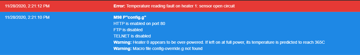
                                    Still doing this after fully power cycling the printer.

                                    update2 (2).jpg update1 (2).jpg

                                    1 Reply Last reply Reply Quote 0
                                    • Phaedruxundefined
                                      Phaedrux Moderator
                                      last edited by

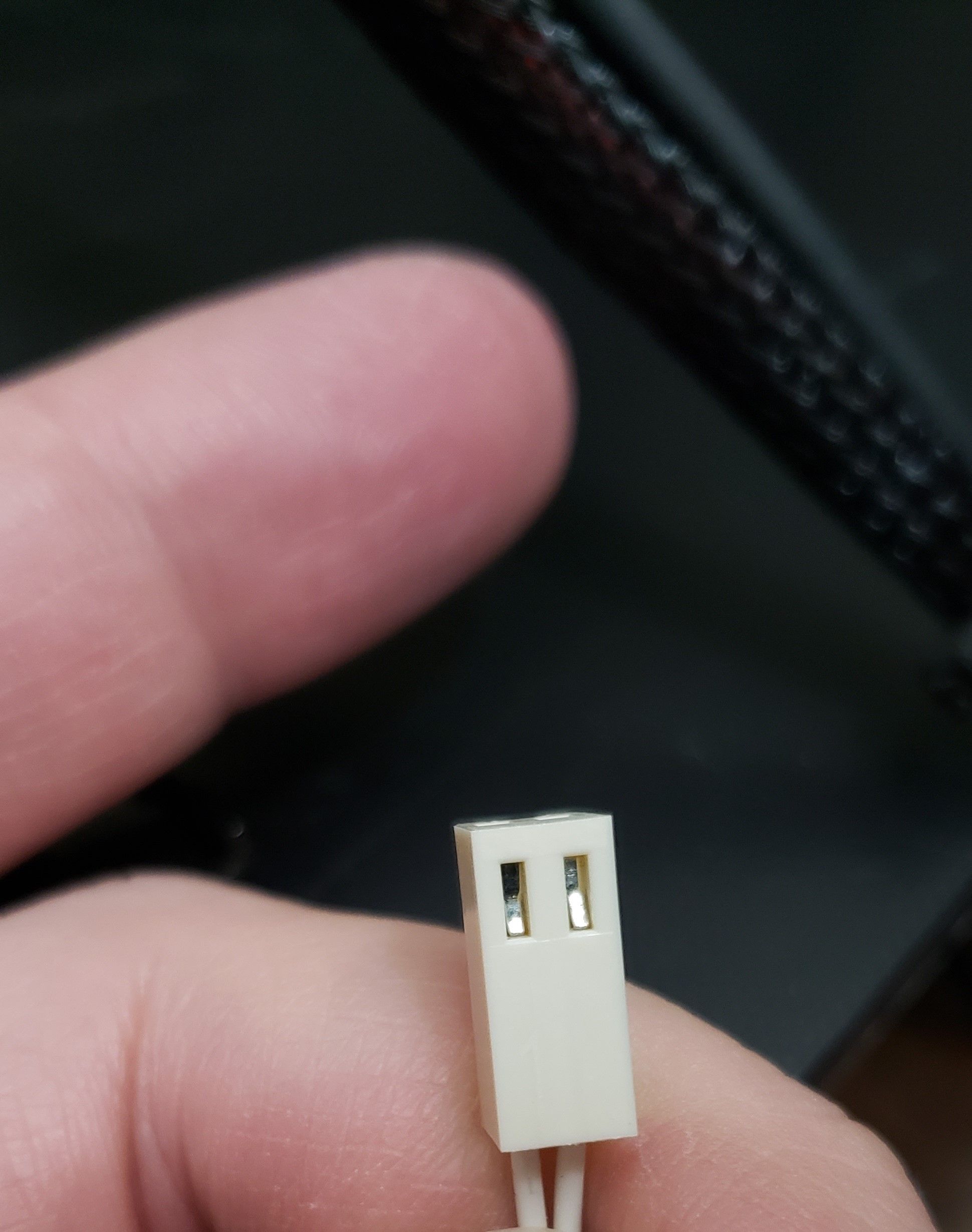
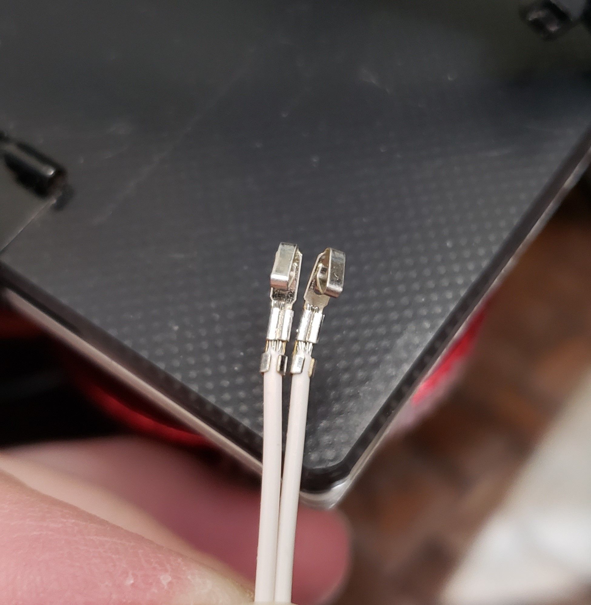
                                      It's showing open circuit on both your heaters. Are the wires actually connected? Bad crimp?

                                      Z-Bot CoreXY Build | Thingiverse Profile

                                      1 Reply Last reply Reply Quote 0
                                      • Destruct0Danundefined
                                        Destruct0Dan
                                        last edited by

                                        Not my best but not my worst. Pins are seated properly too.
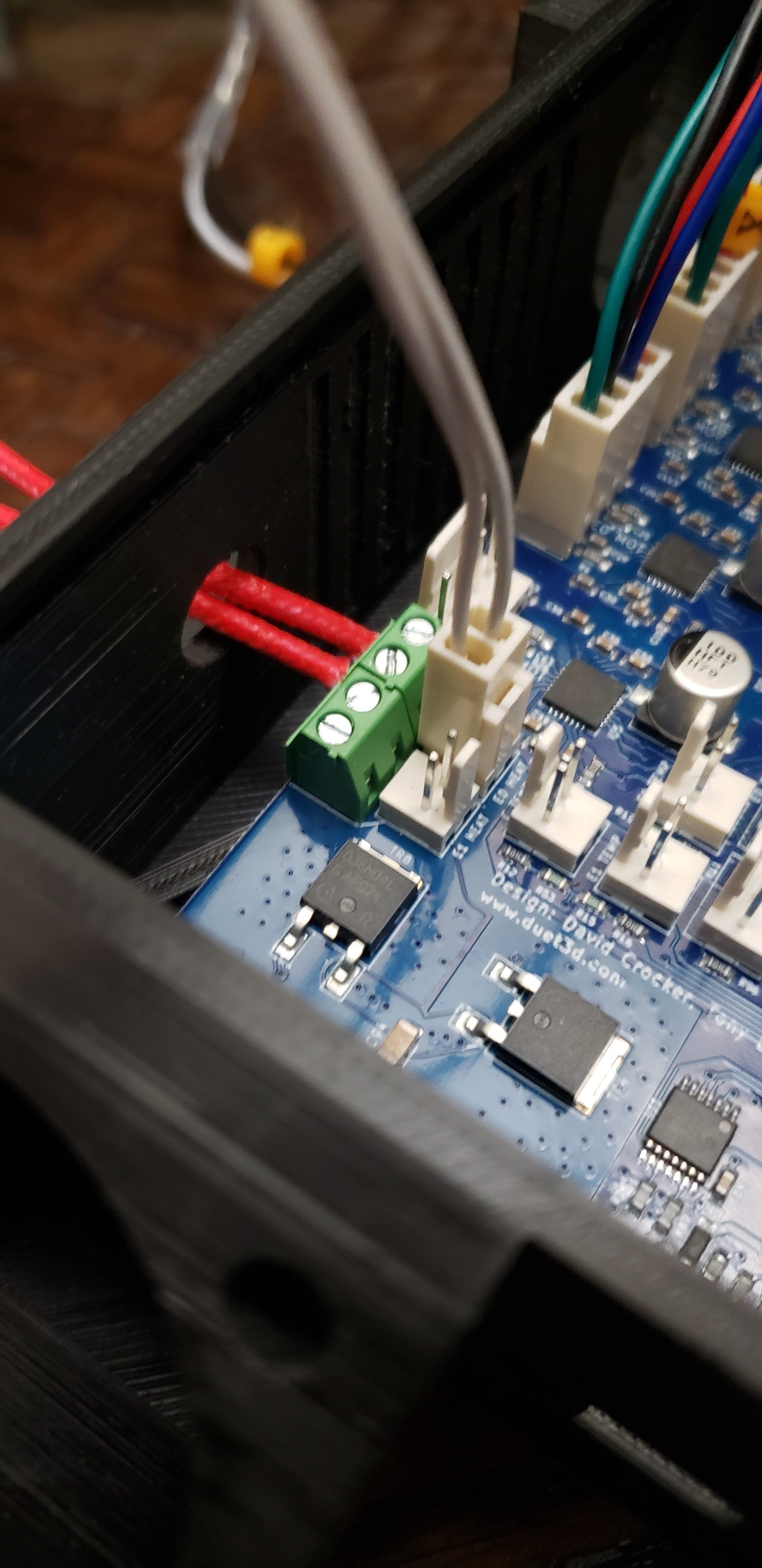
20201128_192147 (2).jpg 20201128_191939 (2).jpg

                                        1 Reply Last reply Reply Quote 0
                                        • Destruct0Danundefined
                                          Destruct0Dan
                                          last edited by

                                          Just to verify
                                          20201128_192632 (2).jpg

                                          1 Reply Last reply Reply Quote 0
                                          • A Former User?
                                            A Former User
                                            last edited by

                                            Last picture show the thermistor connected in parallel with the heater element.

                                            The two pin header labeled E0 Temp is probably the one you wanted to use. It would help to measure the resistance across the two wires coming from the thermistor if it doesn't work on the correct input to see if the sensor/wiring is okay or not. I guess if subjected to Vin for some time it might not survive due to the heat generated as the resistance drops with increasing temperature.

                                            Destruct0Danundefined 1 Reply Last reply Reply Quote 0
                                            • First post
                                              Last post
                                            Unless otherwise noted, all forum content is licensed under CC-BY-SA