G29 / 3 point bed compensation - always tilted slightly
-
So my issue is that I have a COREXY printer with 3 independent leadscrews, a bed with PEI sheet on it, and a BL touch probe. Whenever Im homing the printer, 1 corner is always a bit lower than the rest - The corner towards home XY (0,0) is alway low, and maximum XY (320,290) always sits high.
If I run it more than once, it gets better, but since its alway off on first try around the same, I would suspect it be possible to fix it with better settings - But I cannot figure out the math in what seting is wrong.
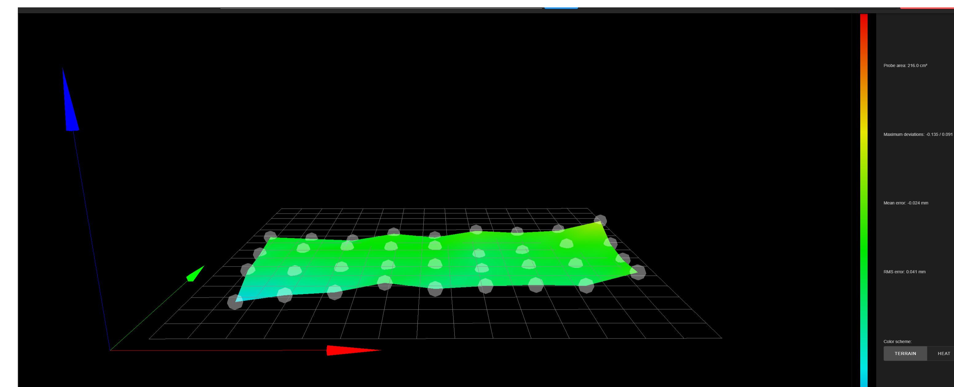
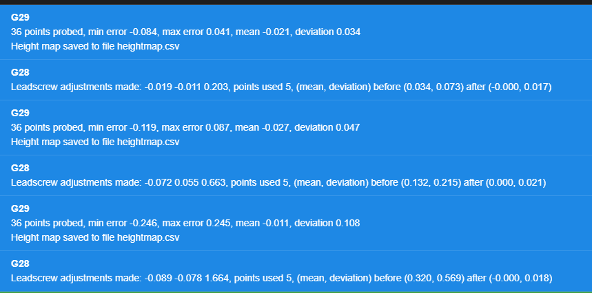
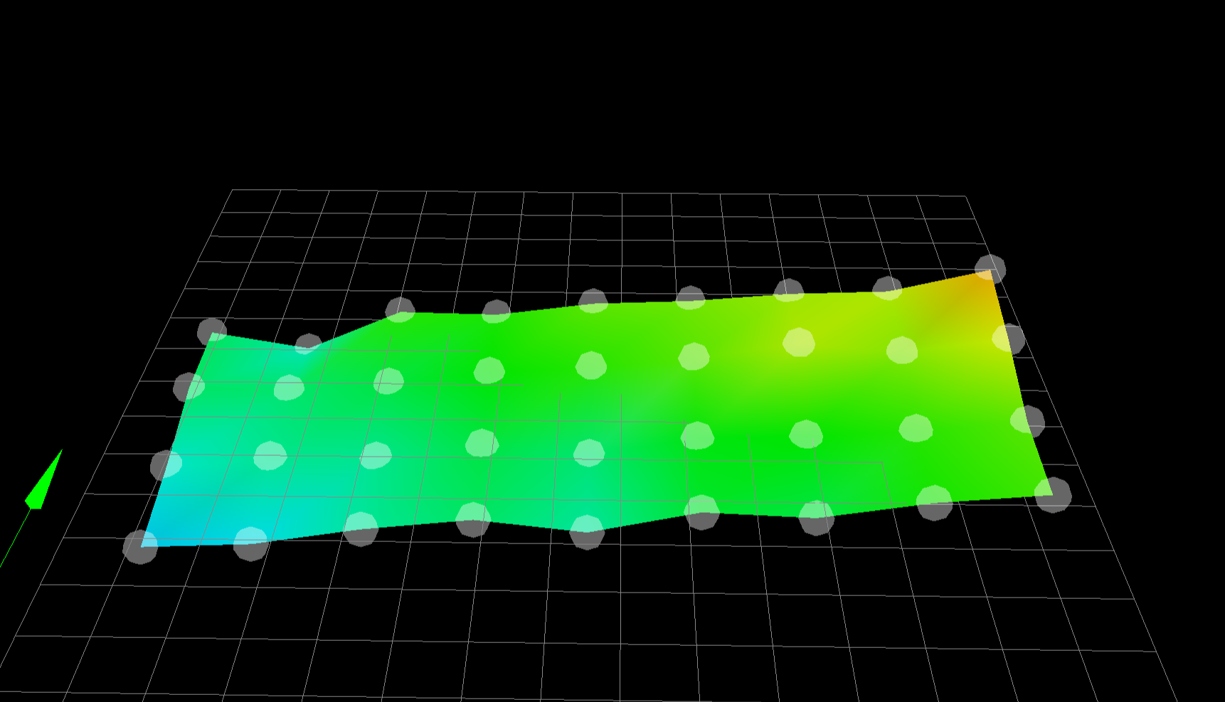
Here you can see the probe tests:
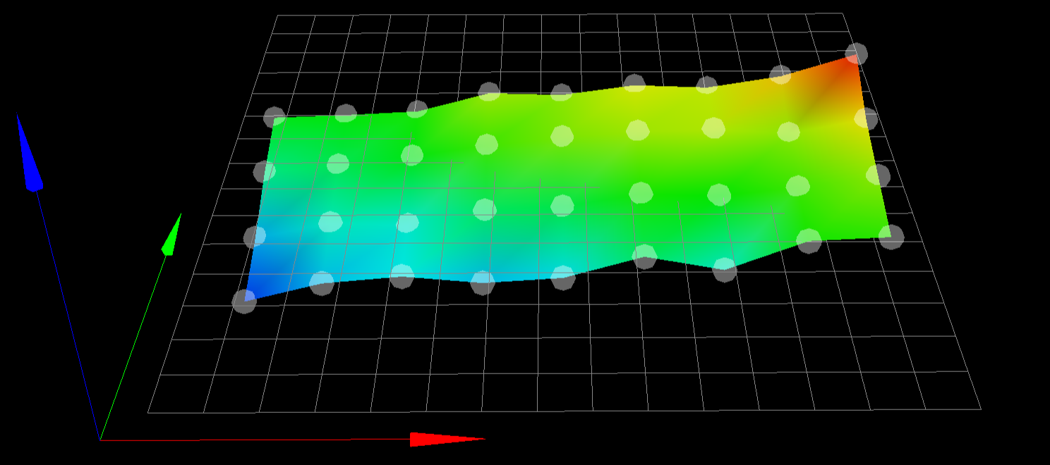
And the bed results after 1 homing:
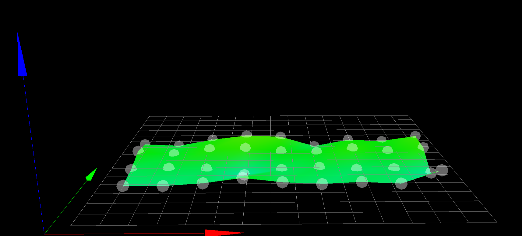
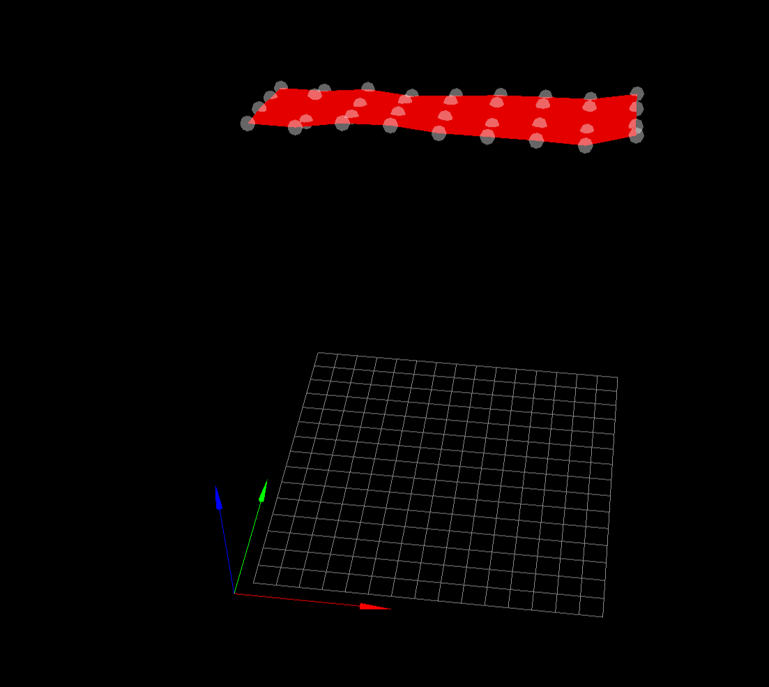
Then 2 homing:

And then 3 homing:
As seen, the lower left corner is a bit low.
The most relevant of the settings gcode is here:
; Z-Probe M558 P9 C"^io7.in" H5 F300 T6000 ; set Z probe type to bltouch and the dive height + speeds M950 S0 C"io7.out" ; create servo pin 7 for BLTouch G31 P500 X30 Y70 Z1.48 ; set Z probe trigger value, offset and trigger height M557 X40:300 Y80:195 S30 ; define mesh grid ; Define the X and Y coordinates of the leadscrews. ; Must come after M584 (Set drive mapping), M667 (Select CoreXY Mode) and M669 (Choosing Kinematics type) ; Motor order: Front left (1), front Right (2), rear right (3). ; Snn Maximum correction in mm to apply to each leadscrew (optional, default 1.0) M671 X-55:360:360.0 Y170:40:310 S20 P2 The bed is shaped like this, where the red is the leadscrews:
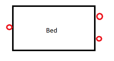
The coordinates from the screws have been measured by homing the printer, then moving the nozzle as close to the leadscrew, and measure the offset with a ruler.My guess is one of the coordinates is offset, but I cannot figure out which one

-
@Martin1454 said in G29 / 3 point bed compensation - always tilted slightly:
F300
With a bltouch, you need to probe slower F120 is a better value.
post you bed.g and your homeall.g
if you have 3 leadscrews why are you probing 5 points?
-
@Veti said in G29 / 3 point bed compensation - always tilted slightly:
@Martin1454 said in G29 / 3 point bed compensation - always tilted slightly:
F300
With a bltouch, you need to probe slower F120 is a better value.
post you bed.g and your homeall.g
if you have 3 leadscrews why are you probing 5 points?
Aha, will lower that then.
I probe 5 points as I got a bit better results with that, even though I know only 3 points is needed to define a plane.
But if it only needs 3 points with the right setting, it would be perfect!here is the 2 files:
; bed.g ; called to perform automatic bed compensation via G32 M561; Clear bed height map ; Probe the bed at 5 points G30 P0 X30 Y80 Z-9999; G30 P1 X30 Y260 Z-9999; G30 P2 X280 Y260 Z-9999; G30 P3 X280 Y80 Z-9999; G30 P4 X135 Y160 Z-9999 S3; ; homeall.g ; called to home the X axis ; ; generated by RepRapFirmware Configuration Tool v3.1.4 on Mon Oct 12 2020 17:14:31 GMT+0200 (Centraleuropæisk sommertid) G91 ; relative positioning M400 ; M913 X40 Y40 ; Drop current to 70% G1 H2 Z5 F500 ; lift Z relative to current position G1 H1 X-325 F6000 ; move quickly to X axis endstop and stop there (first pass) G1 X5 F6000 ; go back a few mm G1 H1 X-325 F1000 ; move slowly to X axis endstop once more (second pass) G90 ; absolute positioning M913 X100 Y100 ; return current to 100% ; homey.g ; called to home the Y axis ; ; generated by RepRapFirmware Configuration Tool v3.1.4 on Mon Oct 12 2020 17:14:31 GMT+0200 (Centraleuropæisk sommertid) G91 ; relative positioning M400 ; M913 X40 Y40 ; Drop current to 70% G1 H1 Y-325 F6000 ; move quickly to X axis endstop and stop there (first pass) G1 X5 F6000 ; go back a few mm G1 H1 Y-325 F1000 ; move slowly to X axis endstop once more (second pass) G90 ; absolute positioning M913 X100 Y100 ; return current to 100% ; homez.g ; called to home the Z axis ; ; generated by RepRapFirmware Configuration Tool v3.1.4 on Mon Oct 12 2020 17:14:31 GMT+0200 (Centraleuropæisk sommertid) ; Z-axis G91 ; relative positioning M561 ; Clear any bed transform G1 X30 Y80 F6000 ; G30 ; G32 ; Start 3-point probe sequence - Bed.g EDIT: here is first probe with F100:
-
i would advise not to have the G32 in the homez, as the G32 invalidates z=0.
while analysing change the 3 point with points close to the leadscrews.
-
@Veti said in G29 / 3 point bed compensation - always tilted slightly:
i would advise not to have the G32 in the homez, as the G32 invalidates z=0.
while analysing change the 3 point with points close to the leadscrews.
Where would you place G32 then?
-
-
@Veti said in G29 / 3 point bed compensation - always tilted slightly:
in the start g code.
G28
G32
G28 ZSo I tried that, but that gives me a fun offset.
I removed G32 from Homeall and Homez - Then homed all axis from the DWC, and then sent manually G32 and then G28 Z. Then I probed the bed with G29

-
post your new homez
-
; homez.g ; called to home the Z axis ; ; generated by RepRapFirmware Configuration Tool v3.1.4 on Mon Oct 12 2020 17:14:31 GMT+0200 (Centraleuropæisk sommertid) ; Z-axis G91 ; relative positioning M561 ; Clear any bed transform G1 X160 Y170 F6000 ; G30 ; -
post your config.g maybe you set your Dive height wrong
-
@Veti
This is the complete config.g; Configuration file for Duet 3 (firmware version 3) ; executed by the firmware on start-up ; ; generated by RepRapFirmware Configuration Tool v3.1.4 on Mon Oct 12 2020 17:14:31 GMT+0200 (Centraleuropæisk sommertid) ; General preferences G90 ; send absolute coordinates... M83 ; ...but relative extruder moves M550 P"Duet 3" ; set printer name M669 K1 ; select CoreXY mode ; Drives M569 P0.1 S1 ; physical drive 0.1 goes forwards M569 P0.2 S1 ; physical drive 0.2 goes forwards M569 P0.3 S0 ; physical drive 0.3 goes forwards M569 P0.4 S0 ; physical drive 0.4 goes forwards M569 P0.5 S0 ; physical drive 0.5 goes forwards M569 P0.0 S0 ; physical drive 0.0 goes forwards M584 X0.2 Y0.1 Z0.4:0.3:0.5 E0.0 ; set drive mapping M350 X16 Y16 Z16 E16 I1 ; configure microstepping with interpolation M92 X200 Y200 Z800.00 E415.00 ; set steps per mm M566 X1500.00 Y1500.00 Z12.00 E120.00 ; set maximum instantaneous speed changes (mm/min) M203 X8400.00 Y8400.00 Z4000.00 E1200.00 ; set maximum speeds (mm/min) M201 X800.00 Y500.00 Z200.00 E250.00 ; set accelerations (mm/s^2) M906 X1200 Y1200 Z800 E800 I40 ; set motor currents (mA) and motor idle factor in per cent M84 S30 ; Set idle timeout ; Axis Limits M208 X0 Y0 Z0 S1 ; set axis minima M208 X300 Y250 Z480 S0 ; set axis maxima ; Endstops M574 X1 S3 ; Set endstops controlled by motor load detection M574 Y1 S3 ; Set endstops controlled by motor load detection M574 Z0 ; Set endstop Z to be probe M915 X Y H200 S1 R0 F0 ; set X and Y to sensitivity , do nothing when stall, unfiltered ; Z-Probe M558 P9 C"^io7.in" H5 F100 T6000 ; set Z probe type to bltouch and the dive height + speeds M950 S0 C"io7.out" ; create servo pin 7 for BLTouch G31 P500 X30 Y70 Z1.48 ; set Z probe trigger value, offset and trigger height M557 X40:300 Y80:195 S30 ; define mesh grid ; Define the X and Y coordinates of the leadscrews. ; Must come after M584 (Set drive mapping), M667 (Select CoreXY Mode) and M669 (Choosing Kinematics type) ; Motor order: Front right (1), front left (2), rear center (3). ; Snn Maximum correction in mm to apply to each leadscrew (optional, default 1.0) M671 X-55:360:360.0 Y170:40:310 S20 P2 ; Heaters M308 S0 P"temp2" Y"thermistor" T100000 B4138 ; configure sensor 0 as thermistor on pin temp0 M950 H0 C"out0" T0 ; create bed heater output on out0 and map it to sensor 0 M140 H0 ; map heated bed to heater 0 M143 H0 S120 ; set temperature limit for heater 0 to 120C M308 S1 P"temp1" Y"thermistor" T100000 B4138 ; configure sensor 1 as thermistor on pin temp2 M950 H1 C"out1" T1 ; create nozzle heater output on out1 and map it to sensor 1 ; Fans M950 F1 C"out7" Q500 L127 C"Heat sink" ; create fan 1 on pin out7 and set its frequency M106 P1 H1 T45 ; set fan 1 value. Thermostatic control is turned on M950 F0 C"out4" Q500 ; create fan 0 on pin out4 and set its frequency M106 P0 H-1 C"Part cooler" ; set fan 0 value. Thermostatic control is turned off ; Tools M563 P0 D0 H1 F0 ; define tool 0 G10 P0 X0 Y0 Z0 ; set tool 0 axis offsets G10 P0 R0 S0 ; set initial tool 0 active and standby temperatures to 0C ; Custom settings are not defined ; Miscellaneous T0 ; select first tool M501; Read config override -
@Martin1454 said in G29 / 3 point bed compensation - always tilted slightly:
M574 Z0 ; Set endstop Z to be probe
thats not the command for Set endstop Z to be probe
this is
M574 Z1 S2 ; configure Z-probe endstop for low end on ZM308 S0 P"temp2" Y"thermistor" T100000 B4138 ; configure sensor 0 as thermistor on pin temp0
M308 S1 P"temp1" Y"thermistor" T100000 B4138 ; configure sensor 1 as thermistor on pin temp2Your thermistor is configured incorrectly. Find the correct Beta value in your thermistor documentation.
M906 X1200 Y1200 Z800 E800 I40 ; set motor currents (mA) and motor idle factor in per cent
are these correct? what stepper motors do you have?
-
@Veti said in G29 / 3 point bed compensation - always tilted slightly:
@Martin1454 said in G29 / 3 point bed compensation - always tilted slightly:
M574 Z0 ; Set endstop Z to be probe
thats not the command for Set endstop Z to be probe
this is
M574 Z1 S2 ; configure Z-probe endstop for low end on ZM308 S0 P"temp2" Y"thermistor" T100000 B4138 ; configure sensor 0 as thermistor on pin temp0
M308 S1 P"temp1" Y"thermistor" T100000 B4138 ; configure sensor 1 as thermistor on pin temp2Your thermistor is configured incorrectly. Find the correct Beta value in your thermistor documentation.
M906 X1200 Y1200 Z800 E800 I40 ; set motor currents (mA) and motor idle factor in per cent
are these correct? what stepper motors do you have?
The motors are all E3D high torque motors rated at 1.6A, except the extruder which is a small pancake stepper - current seems okay on it - Will look into the thermistors and change it from M574 Z0 to Z1 S2
EDIT: I got the Z0 from the Gcode page
"The S2 option of M574 is intended for use only when axes other than Z are using the Z probe for homing. The only printers known that do this using Duet electronics are the RepRapPro Ormerod, Huxley Duo, and Mendel Tricolour machines. When using the Z probe to home Z, M574 Z0 should be used." -
so you are running your z steppers with not enought current
set the current to 1200
-
@Veti
Increased the current to 1200 - still gets the large offset

-
that make zero sense.
G28 Z should establish Z=0 using G30.
G29 getting a different offset would mean that the trigger point is different.
-
@Martin1454 said in G29 / 3 point bed compensation - always tilted slightly:
G1 X30 Y80 F6000 ; G30 ;
@Martin1454 said in G29 / 3 point bed compensation - always tilted slightly:
G1 X160 Y170 F6000 ; G30
Your homeall and homez place the probe at different locations. Make them the same.
-
@Phaedrux Hmm....
That got me thinking - I Use the X30 Y80 because that places the probe not that far from my first lead screw and that saves time since it doesnt have to move when it starts the 3 point leveling - But! since it is not level when it does the first zeroring of Z, will placeing it off center, make the axis it rotates about not centered also? Or since its a plane, it doesnt matter?
But I'll change it when I get home
-
Are you certain that you dont have a dropped corner on one of your axis?
-
You also need to remember there is a huge difference between a surface being level and it being flat...
if it ispossible to use a digital inclinometer you can check the level, first zero the inclinometer to the surface the printer sits on (firstly on the X axis) then carry out 3 point leveling and check how level it is, then zero the inclinometer on the surface on the Y axis orientation and carry out the same 3 point leveling and see what it says. and you will have your answer, which i think might be that your bed it level but not completely flat.
you can also check that your rails are level too.