A Software Solution to Eliminate Ringing?
-
Thanks for your input @bot!
Have you seen the variable ringing effects that change with the belt segment length, or is this just theory?
No, I've not seen it at all, so it's more of a hypothesis than theory at this point. Would love some help to test it though.
I have a cartesian printer, and would be interested in verifying whether the ringing is different if the toolhead is at different locations. Do you have any tests in mind that I could perform that would be helpful to show you?
That would be great! I'd simply print two hollow test cubes at two different positions on the bed. One close to the stepper, another one far away. Print at settings that excite ringing. Say ≥80mm/s, high acceleration (5000~10,000 mm/s) and compare the ringing frequency. If the model is true there should be a significant difference in ringing frequency at the two sides.
I have a hope that you could be wrong about the variation. A guitar string has a fixed length by having two fixed points. The wave originates as a transverse wave from a plucked string.
On the other hand, a belt system has one fixed point: the motor pulley, with an idler. There is still tension beyond the idler. The wave from motion is more of a longitudinal wave, isn't it? So the idler doesn't exactly perfectly impede the wave. It might dampen some of the transverse waves that may be induced, but the longitudinal wave seems like it would be able to "flow" right on past the idler, because the belt itself is what determines the position of the idler.
Interesting thought. If true, it would dramatically simplify things, although I don't think it's going to be true.
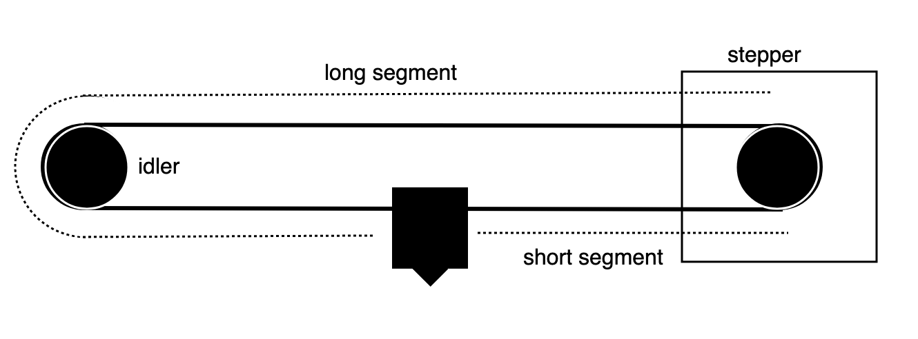
I don't consider the idler at all. I'd consider it as a very weak damper for longitudinal force propagation. The three points on the belt I consider are the two attachment points to the end effector and the motor pulley in between. We operate far below the propagation speed of the longitudinal wave, so I think we can think of the belts as operating in DC mode with the motor pulley applying a tension force on one belt segment and relaxing the force on the other segment. I.e. the only dynamic component that matters is the end effector's inertial movement.Edit: Here's a quick sketch:
-
I also have a feeling you're right. I was just trying to come up with some way that it would be more simple! haha. I will perform some tests like you recommend.
Edit: @DigitalVision With your updated sketch, I understand more clearly how you are thinking of the system.
So if the "short segment" is as long as possible, that is the worst case scenario?
Edit 2: Now that I understand what you mean, and think about it a little bit, it seems obvious that what you are saying is likely true. I have about 8 hours of printing to do before I can do the tests but I will get to it as soon as possible.
-
So if the "short segment" is as long as possible, that is the worst case scenario?
Correct. The belt segments get less compliant the shorter they are. If your belt's total length is 1, when you combine the two belt segments in parallel, the net compliance is proportional to x*(1-x). The maximum for this expression is at x=0.5 – i.e. the middle of the belt.
-
I did some quick tests. This seems like evidence in support of your theory. I wasn't able to precisely measure the frequency differences, but there is clearly some differences in frequency happening.
Just FYI: I have a ridiculously long primary drive belt on my Y axis, which I think is causing havoc and also creating its own ringing that is interacting with the other ringing...
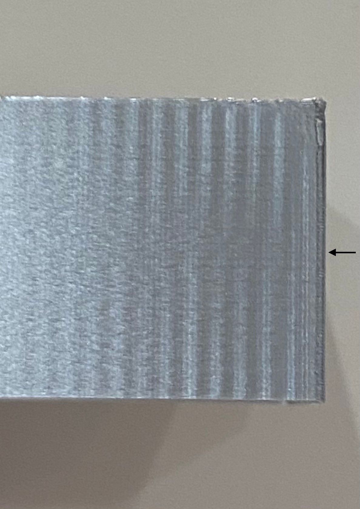
Nonetheless, this shows the front face, which is printed from top to bottom in this picture, along the X axis in a positive direction. One is printed "best case" for both axes, one is printed "worst case." The one on the right is "best case."
I had to increase my print acceleration from 1200 to 5000 to be able to see this large difference. My initial tests had much less ringing, and it appeared identical. I have to rule out that Y axis primary belt from the equation before this is useful.
It seems like a good strategy for the time being (for avoiding the effects of this variation) is to simply select an acceleration value that is low enough to not exhibit ringing to any discernible amount: this way, the variation is basically irrelevant. Do you think s-curve acceleration alone, before any cancellation of frequencies, would provide speed benefits in this regard? By this I mean, instead of trying to dynamically cancel out any ringing, by simply choosing conservative values that don't exhibit enough ringing to care about the variation: would S-curve help speed up the print in this case, while maintaining the "invisibility" of the ringing? Sorry if that question derails the topic too much for you.
*not actually a robot
-
S-curve acceleration reduces high frequency ringing, but the maths indicates that it actually increases ringing at some lower frequencies assuming you keep the total acceleration time constant. Whether a frequency counts as "low" or "high" depends on how its period compares to the total acceleration or deceleration time.
Duet WiFi hardware designer and firmware engineer
Please do not ask me for Duet support via PM or email, use the forum
http://www.escher3d.com, https://miscsolutions.wordpress.com -
@dc42 In my experience, it's easy to avoid the low-frequency ringing by choosing sensible acceleration/jerk/speed settings. It's the high-frequency ringing that is nearly impossible to be rid of. No matter how low of a jerk and accel/speed value I use, there is always a tiny amount of HF ringing.
Maybe I'm tuning things wrong, but I've been through basically the entire range of combinations and it reacts quite predictably.
I think, dc42, you've been right all along that the instantaneous speed change "problem" is the one to focus on first. The last bit of HF ringing I get seems related to jerk more than acceleration, and finding a low enough "jerk" speed for sharp corners while maintaining curve speed/quality is kind of impossible.
I don't mean to derail the thread. I'm very interested in the dynamic cancellation of ringing, if possible! But there is groundwork to be laid first, I think.
*not actually a robot
-
@bot thanks for running this test. I must say it's hard to spot the ringing in the pictures. One thing I found useful was to limit the y axis acceleration to a very low value, say 500 while increasing x axis acceleration to a high value to avoid the cross talk. (Also make sure you've adjusted both M204 and M201).
It seems like a good strategy for the time being (for avoiding the effects of this variation) is to simply select an acceleration value that is low enough to not exhibit ringing to any discernible amount: this way, the variation is basically irrelevant.
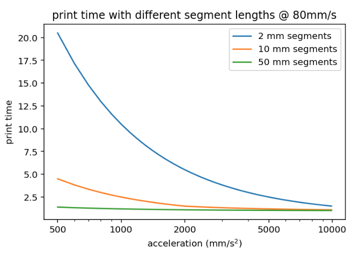
The ringing magnitude is proportional to the acceleration so while you can mitigate it with lower acceleration settings it has the potential to affect the print time significantly, especially on print geometries with shorter path lengths. An illustration of print speed vs acceleration for different segment lengths.
Do you think s-curve acceleration alone, before any cancellation of frequencies, would provide speed benefits in this regard?
In addition to what dc42 said – the photo at the very top of this topic shows an s-curve vs linear acceleration ramp profile without any appreciable difference in ringing.
-
So it's safe to say we can rule out S-curve as beneficial? Or it is only beneficial with your modelling implementation?
I definitely understand the print time implications of acceleration, and will support any and all theories which can improve print time while maintaining or improving quality.
I have highlighted the photo to better show what I think are signs of ringing. By my eye it's easier to see and tell that they are at least different, which supports your theory.

*not actually a robot
-
@bot said in A Software Solution to Eliminate Ringing?:
I think, dc42, you've been right all along that the instantaneous speed change "problem" is the one to focus on first. The last bit of HF ringing I get seems related to jerk more than acceleration, and finding a low enough "jerk" speed for sharp corners while maintaining curve speed/quality is kind of impossible.
I personally don't think the implementation of "jerk"/instantaneous speed change as implemented in all current firmwares is very good. The purpose of jerk is to allow continuous speed through linearly segmented curves, but as a consequence you get abrupt changes (and ringing) for sharp corners too. A quick thing I don't know has been tested and I would expect to be a better heuristic would be to add a corner angle threshold and disable jerk for any corner beyond a certain angle. This is quite often used in 3D graphics as a heuristic to for when to smooth vs flat shade a 3d mesh and seems to work fairly well. You may want to mix in segment length as well in a heuristic, but in either case it shouldn't be hard to prevent "jerk" from applying to a 90° corner between two long segments.
-
@bot said in A Software Solution to Eliminate Ringing?:
So it's safe to say we can rule out S-curve as beneficial? Or it is only beneficial with your modelling implementation?
I'd be surprised if s-curves by themselves allow you to increase the print speed, but they will eliminate the HF transients at the ends of ramps. The trade-off is that they lead to higher peak accelerations if you want to preserve the same print time, and that means that you load the "spring" more. But s-curves allows the spring compensation model to work without requiring instantaneous position changes. And I've found this allows for substantially higher accelerations.
I have highlighted the photo to better show what I think are signs of ringing. By my eye it's easier to see and tell that they are at least different, which supports your theory.
Thanks, those lines help! Could you give a rough estimate of the short and long belt length for the two print locations?
-
@DigitalVision Sure the belt lengths are like this:
It's a 50 mm edge length on that print
X axis "best case"
Short length: 166 mm to 216 mm
Long length: 970 mm to 920 mmX axis "worst case"
Short length: 366 mm to 416 mm
Long length: 770 mm to 720 mmY axis numbers are similar.
-
@bot said in A Software Solution to Eliminate Ringing?:
Short length: 166 mm to 216 mm
Long length: 970 mm to 920 mm
X axis "worst case"
Short length: 366 mm to 416 mm
Long length: 770 mm to 720 mmCool. Your "best" case should have up to 75 % higher spring constant than the worst side (very dependent on which side of the print was at the most extreme point). If your belts dominate ringing, this should translate into ~32% higher ringing frequency, so the good side ringing period should be as little as ~3/4 of the worse side (with the stepper motor and other serial springs the difference will be slightly smaller though). That seems possible from your photo.
I don't know what that secondary ringing at around 2/3s of the print is though. That far too early to be at the deceleration ramp but also too late to be a late residual from the earlier corner.
-
@DigitalVision I think it's best not to look to deeply into my tests. I didn't isolate the Y axis as you mentioned, and my Y axis is insanely stupid to begin with (there is a longer "short side" on the primary drive than at any point of the secondary drive belt. I don't know what I was thinking at the time). I have plans to change it to be "the same" as the X axis, just with more weight to move around. Then I will perform more tests.
All I wanted to do was confirm or deny the idea that the ringing was variable (in frequency) depending on where it was printed. I feel like I confirmed that and your theories all seem to line up.
So, given all that, would using your method be as simple as determining the different frequencies at different parts of the axes, and cancelling as required based on position?
-
@bot said in A Software Solution to Eliminate Ringing?:
So, given all that, would using your method be as simple as determining the different frequencies at different parts of the axes, and cancelling as required based on position?
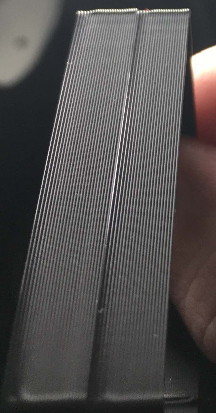
Yes, in theory at least. For a cartesian all you would need is to determine the frequencies at two different positions per axis and provide the positive and negative belt lengths at a known location. One could probably create a nice script to automatically generate the right structures to print at the known locations. I found it most easy and consistent to spot the acceleration ringing (where the extrusion width oscillates), and especially when printing in a semi-translucent material. Here's a photo on silver filament which is very hard to capture on photo showing the phase inversion in the ringing pattern as the f_n parameter was varied across the print z. If you get it right, there is a rather sharp region without ringing that's fairly easy to spot and measure:
-
@DigitalVision The results are truly fantastic.
Do you think it would be easier or harder to determine the "positional frequency" on a corexy machine? A delta?
*not actually a robot
-
This post is deleted! -
@bot a CoreXY has a more complex model, but it seems to be enough to measure 3 points per axis instead of 2. I haven't yet started to work on a position dependence model for a delta yet – and I still need to get some time to implement and test the CoreXY one. The delta geometry is more symmetric, so it may be easier to calibrate – unless the wire bundle ends up messing up things. I did get great results in the center of bed though, and I haven't yet tested how they vary with position.
-
Another approach that should be very straightforward for calibrating the ringing dynamic would be to attach a cheap MEMS accelerometer to the print head and log samples at different locations. Accelerometers with up to 8kHz sampling rates are less than $1 each in volume. Determining the ringing frequency should be trivial and very accurate.
A more crazy idea: You could easily build a closed loop system with an IMU. The filter lag in an accelerometer can be as low as 1 ms, and with say 1kHz sampling we’d be well within reasonable latencies. So you could simply measure the x,y,z acceleration in real-time and compare to the desired acceleration - and apply a motion compensation signal (using the spring model) to correct for any deviation.
-
@DigitalVision klipper's input shaper implementation uses an ADXL accelerometer to measure vibrations and and configure the input shaper.
-
@bot said in A Software Solution to Eliminate Ringing?:
@dc42 In my experience, it's easy to avoid the low-frequency ringing by choosing sensible acceleration/jerk/speed settings. It's the high-frequency ringing that is nearly impossible to be rid of. No matter how low of a jerk and accel/speed value I use, there is always a tiny amount of HF ringing.
That's exactly opposite to my experience. I find low frequency ringing to be a problem at any sensible acceleration. I would need to use really low acceleration to avoid it, which would slow the prints down too much.
Duet WiFi hardware designer and firmware engineer
Please do not ask me for Duet support via PM or email, use the forum
http://www.escher3d.com, https://miscsolutions.wordpress.com