Duet3D Logo Duet3D
    • Tags
    • Documentation
    • Order
    • Register
    • Login
    1. Home
    2. DigitalVision
    • Profile
    • Following 0
    • Followers 2
    • Topics 6
    • Posts 60
    • Best 23
    • Controversial 0
    • Groups 0

    DigitalVision

    @DigitalVision

    61
    Reputation
    57
    Profile views
    60
    Posts
    2
    Followers
    0
    Following
    Joined Last Online

    DigitalVision Unfollow Follow

    Best posts made by DigitalVision

    • A Software Solution to Eliminate Ringing?

      Some background. One of my 3D printers is a fairly large delta printer (Ultibots D300VS+, ø300mm, 1000mm verticals) with a direct drive extruder (Titan Aero). This printer hasn't gotten much use since the heavy end effector combined with the long motion arms make it very susceptible to ringing and overshooting even at very moderate print speeds.

      One of the key reasons for the lack of rigidity on this specific printer was that the original delta carriers were manufactured in a somewhat flexible material. A few weeks ago, I machined new ones in aluminum, and while this dramatically improved the rigidity and printing performance, ringing was still significant. I contemplated converting it to a Bowden design, but before doing that I wanted to test an idea I've had for a while but never really had the chance to develop: Could we reduce ringing by making the motion control be more aware of the dynamics of the mechanical system?

      The general idea is that 3D printer mechanics can be modeled as mass-spring-damper systems, with the "spring" coming from the electrical field in stepper motors, elasticity in belts and the flexibility in other motion components. For deeper discussion and analysis, I did a little bit of modeling and simulation, summarized in this short write-up:

      https://digitalvision.blog/spring-damper-control

      The approach from that analysis turned out to be remarkably simple and like many other ideas seems to work well in theory, but as we know, the difference between practice and theory is always greater in practice than theory. To get some signal on the practical validity, I prototyped a test on the actual printer, and here are the first results.

      IMG_8284.jpg

      A (somewhat janky) video showing the method running live: https://youtu.be/3ze9RwqkLqU

      The specific parameters for the correction above was f_n=40.4 Hz, zeta=0.

      I got these results without making any FW changes. I instead abused the motion planner by feeding it G-code that simulated the required motion profiles. I think the results look pretty interesting and this is probably worth pursuing further.

      One interesting aspect is that this approach has many similarities to extruder pressure advance. One key difference is that mechanical motion is generally underdamped (zeta<1), while pressure advance is probably overdamped (zeta>1), although I've certainly seen cases where the extruder has a pulsing or oscillating behavior.

      It should be noted though that there are two big limitations to this approach.

      1. This approach does in theory rely on s-curve acceleration profiles (continuous acceleration profiles) in order to give a continuous control signal. It's possible that an approximation will allow it to work reasonably well with classic constant-acceleration profiles (the simulation indicates this), but s-curve acceleration is certainly preferred. Maybe this will end up being the key value proposition for s-curves.
      2. For a similar reason, this approach is incompatible with the "instantaneous velocity change" method that we are used to. I'd like to write a bit more about this later, but the tl;dr is that I think it's time to move away from instantaneous velocity change toward a more general profile smoothing approach. That will have other nice side-effects too.

      Anyway, I thought I'd look for some feedback here before proceeding to explore prototype an actual FW modification.

      posted in General Discussion
      DigitalVisionundefined
      DigitalVision
    • Pressure Advance Calibration

      (My first post here.) I feel printer tuning is still to a large extent a black art that we should be able to turn into a systematic process. As an experiment, I wanted to see if there was an easy way to calibrate the pressure advance coefficient and hacked together a short python script that generates a sequence of fast and slow linear extrusions.

      In this case I did a rather extreme version where print speed changed between 5 mm/s to 100 mm/s, and the pressure advance setting changed from 0 to 0.2s over 10 mm z height.

      0_1535925110977_IMG_1079.JPG

      In this case the optimal setting looks to be 0.074s. (Extruder is direct driven Titan Aero.)

      I've attached the script advance_cal.py and sample test.gcode if anyone else wants to try. The gcode assumed the bed center is (0,0) and likely requires a preamble (heaters, cooling fan etc). I pasted those from another file.

      Is this generally a valid approach, or am I missing something?

      edit: Updated script to support a bed center parameter, proper print height for z0, and python3 compatibility.

      posted in Tuning and tweaking
      DigitalVisionundefined
      DigitalVision
    • RE: A Software Solution to Eliminate Ringing?

      A short update.

      I managed to get some hours to spend on this today, so I rewrote the test code from before mostly from scratch and turned it into a G-code filter. I can now take a regular slicer output file, pass it through the filter and feed the result to the printer. This makes it easier to do realistic testing. The code only really supports linear paths to far, so curves with high tessellation counts will end up looking terrible, but it should work OK for calibration cubes and similar objects. In the process of rewriting it I also implemented some improved machine limits so I won’t have to worry about it trying to move the Z-axis on my cartesian printer at 120 mm/sec.

      Here are some quick-and-dirty results.

      IMG_8327.jpeg
      speed: 80 mm/s, accel: 10 m/s² (10,000 mm/s²), jerk: 2 km/s³ (2,000,000 mm/s³)

      I'm actually pretty happy with that given that this is a 490 g heavy end effector on 375 mm diagonals. For reference, here's what it looks like without any spring-damper compensation:

      IMG_8333.jpeg
      speed: 80 mm/s, accel: 5 m/s² (5,000 mm/s²)

      Pushing it a bit faster.

      IMG_8335.jpg
      speed: 120 mm/s, accel: 20 m/s² (20,000 mm/s²), jerk: 2 km/s³ (2,000,000 mm/s³)
      Some extrusion glitches, but not much ringing.

      I’ll share the code once I’ve written a little documentation on how to use it as I’d love to get some more testing and learnings.

      posted in General Discussion
      DigitalVisionundefined
      DigitalVision
    • RE: A Software Solution to Eliminate Ringing?

      Here's the python test code if anyone wants to give this a shot.

      https://github.com/OskarLinde/dynamic-motion

      The link contains some preliminary instructions for how to use and calibrate the method. You need at least RRF 2.03 since without the M566 P1 jerk policy the G-Code doesn't execute reliably. I was able to run this on an unmodified firmware for simple objects, but found that I could increase the discretization points and run more complex objects if I made a minor firmware change: I disabled the motion planner (look_ahead) if the current move speeds were below the current instantaneous velocity change settings. With this, the extrusion issues in the 120 mm/s print went away. Oh, I also implemented pressure advance correction the script since the firmware one doesn't work with the type of G-Code the script outputs.

      While there are many limitations as described above I'd love to get some testing of this approach: Were you able to get it to work? Were you able to see any improvements in ringing or improvements in print speeds? What type of printer and what calibration values did you land on?

      posted in General Discussion
      DigitalVisionundefined
      DigitalVision
    • RE: [Solved] Curious wood grain pattern on Core XY prints

      The issue is solved now. Thanks everyone for valuable input.

      0_1538894757532_IMG_6457.jpg

      The fact that I got slightly different grain density between 0.6 and 0.4 mm extrusion width made me suspicious. Looking deeper at the grain patterns, comparing them side-by side, I found that they were not perfectly consistent print-to-print. This made me suspect something mechanical.

      The other clue was the fact that the grain patterns changed not with Z, but with layer count. Basically, the shift happened every time the y axis moved. And what could mechanically gradually shift several centimeters over the duration of a print? I could think of only one thing. The recirculating balls in the linear bearings. So I took my y axis apart. The motion of the two bearings felt perfectly smooth when moved by hand, but I still took them apart, took all the balls out – cleaned them with mineral spirits and dried them with ethanol – and among the small pieces of dust and debris that came out of one was what looked like a tiny piece of aluminium shaving. Repackaged them with PTFE grease and issue solved.

      @phaedrux said in Curious wood grain pattern on Core XY prints:

      0.08 seems a little high for a direct drive extruder

      I calibrated it using this technique: https://forum.duet3d.com/topic/6698/pressure-advance-calibration Really quick method to get the value dialed in accurately. (The only other thing I needed to do was to increase the default infill-to-perimeter overlap setting in my slicer, since you can no longer rely on blobbing at the end of long infill lines to fill in the gaps.)

      @rcarlyle said in Curious wood grain pattern on Core XY prints:

      Is it more visible at higher print speeds or lower print speeds?

      Changing print speed made almost no difference at all.

      posted in Tuning and tweaking
      DigitalVisionundefined
      DigitalVision
    • How accurate are mechanical endstops

      I reconfigured my 3 stepper/leadscrew bed to use 3 independent drivers instead of 2 (getting a DueX2 for the one extra driver needed) and added a mechanical endstop on each axis homing the bed like a delta printer. It works well – but one thing I wanted to test was how repeatable the endstops were.

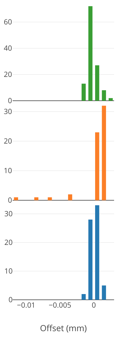
      The firmware doesn't seem to offer a way to test this apart from possibly reconfiguring the endstop under test into a temporary zprobe – so I made a simple simple firmware hack to addH4 option to the G1 command to stop – but not re-home the axis on an endstop hit. I could then log the reported Z pos and repeat multiple times for the three different endstops. Plotting the results as histograms:

      0_1537942747721_58eceae5-b2e2-4982-9001-fd46ad0c5549-image.png

      Some interesting observations. The green and blue endstops seem to be accurate to within ±2 µm (when doing the final homing at 100 mm/min feedrate) which was better than I expected. The orange one had a few outliers –(late triggering) of up to -12 µm – which is probably still not a big deal but higher than necessary. I'll replace this endstop eventually.

      One simple way to improve the homing accuracy that I've used in the past on another firmware is to multi-tap the endstop (e.g. 3,5 or 7 times) and pick the median value. The way RRF is designed though I don't see a straightforward way to implement this. Maybe if there was a g-code command to add the current position to a median accumulator register – and another g-code to move to the accumulated median position plus an offset this could all then be implemented as macros. This functionality could also be used for improved bed probing accuracy.

      Anyway, just thought I'd share this. Having a way to measure endstop accuracy seems like a nice feature to add (something like the H4 option described above), and a way to improve endstop accuracy by filtering out outliers by picking the median position.

      posted in Duet Hardware and wiring
      DigitalVisionundefined
      DigitalVision
    • RE: A Software Solution to Eliminate Ringing?

      Another update.

      Before sharing the python code, I wanted to test it on at least one other printer. This time on a cartesian (CoreXY) printer with CPC linear rails. The printer x-axis is made up of one single 15mm rail with a sole runner block holding the hotend and extruder assembly. The rail itself is very rigid. The weak point is instead the x-axis carrier/runner block that has a bit of yield to its roll axis (resulting in ringing along the y axis).

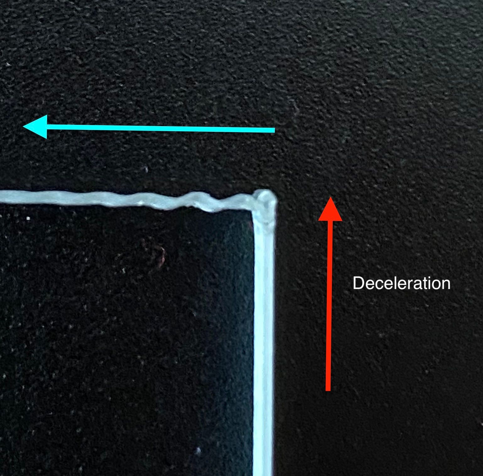
      In getting the calibration done for this printer I learned a number of new things. First, and very importantly there are actually two modes of ringing. The first one is the one we classicality think of as ringing. It occurs after the printer has decelerates down to a full stop and the end effector oscillates. The photo below illustrates this.

      deceleration.jpg

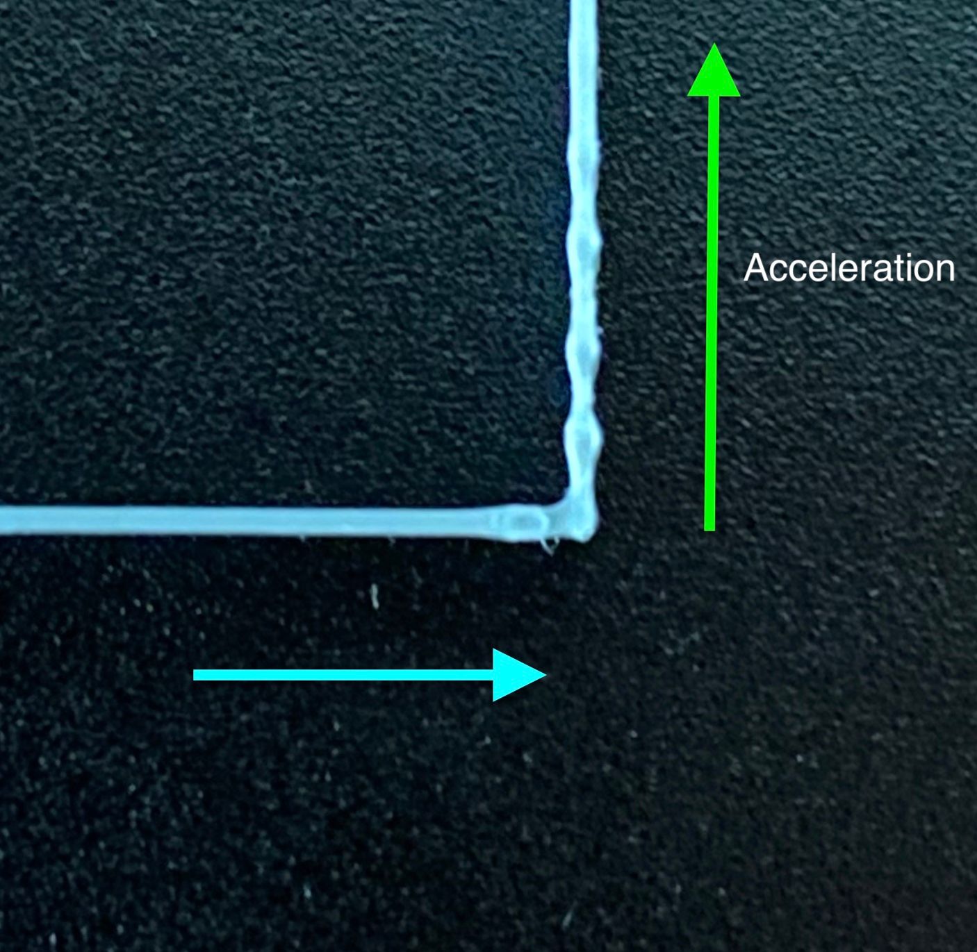
      The second type of ringing was something I hadn’t considered before. It’s ringing that happens during the acceleration phase. If you look carefully you can see it happening in the simulation in the first figure in https://www.digitalvision.blog/spring-damper-control. The effect may look subtle in that animation, but the result on an actual print is much more substantial. The effect is that the extrusion bead gets stretched and compressed periodically.

      acceleration.jpg

      The effect of this is what I suspect often prevents getting consistent extrusion when printing at high speeds. The extrusion gets ripped apart in the stretching phase. After correcting for this ringing I’ve been able to print consistently even at 150 mm/s with 10 m/s² accelerations, something that I’ve never managed before.

      When observing ringing on a print, you will often see a compound effect of both of these two modes of ringing, with the acceleration ringing from e.g. the x-axis compounding with the post-deceleration ringing from the y-axis. When the two axes have different natural spring frequencies the two axis parameters can be hard to tease apart. For that reason, I came up with the strategy of isolating one axis at a time by setting the acceleration limits of the other axis to a very low value. E.g. 10 m/s² acceleration on the y axis with 0.5 m/s² acceleration on the x.

      My final issue with calibrating this printer was that I was unable to find a single setting that eliminated the ringing on both the left and right side of the print. The left side had a ringing frequency of ~52 Hz with the right side closer to 60 Hz. It seems like the ringing had different frequencies when moving in the positive y direction vs the negative. Thinking a bit about this I came up with a model that makes sense. The print head is not perfectly balanced under the axis with the center of gravity being offset to one side. This effectively means that gravity is applying pre-tension on the spring biasing the spring effect towards one direction. To test this hypothesis I implemented an asymmetric spring model and plugging in 52 and 60 Hz respectively for the two axes did the trick.

      posted in General Discussion
      DigitalVisionundefined
      DigitalVision
    • RE: A Software Solution to Eliminate Ringing?

      @DigitalVision said in A Software Solution to Eliminate Ringing?:

      @sebkritikel said in A Software Solution to Eliminate Ringing?:

      Not quite there yet, but narrowing it down some - the after here is taken at f_n X to 21Hz, f_n Y to 30Hz (X picked after running from 19-26, Y a number of times from 15-50).

      I curious how you end up with such low frequencies and what's dominating the X-spring in your system. Are your belts fairly loose? How long is the X travel?

      A quick theoretical calculation on the timing belt contribution:

      From Gates' datasheet, a GT3 2mm pitch, 6mm wide belt has an elongation of 0.1% @ 16.9 N of force. If we assume that the extruder is 500 g and running at 10,000 mm/s² accelerations we get 5 N of force. That would correspond to an elongation of 0.03 % or 0.3 mm/m. For a belt that is is 1 m, this corresponds to a spring constant of k=17000 N/m. The natural frequency is sqrt(k/m)/(2π) = 29.3 Hz. A 500 mm belt would have a natural frequency of 41.5 Hz.

      I have a CoreXY so there are two belts pulling the extruder. My shorter x belt length from extruder to the motor pulley is ~300 mm at the center and the longer ~1050 mm.

      The long belt will have a spring constant of k=15.9 N/mm and the short one k=55.6 N/mm. Since the two springs work in parallel we can simply add the two spring constants getting k=71.5 N/mm.

      Assuming 500g of extruder weight we get f_n = sqrt(71.5 * 1000 / 0.500) / (2*π) = 60.2 Hz. That's remarkably close to the 60.5 Hz number I got from tuning.

      posted in General Discussion
      DigitalVisionundefined
      DigitalVision
    • RE: Pressure Advance Calibration

      Here's another example on a different printer with a different extruder. Holding the print up to the light clearly shows the inverted color gradients showing differences in extrusion volumes.
      0_1535998086477_IMG_6349.JPG

      @deckingman said in Pressure Advance Calibration:

      @digitalvision Did you really mean extrusion rate between 5 and 100mm/s or did you mean print speed? I suspect the latter as an extrusion rate of 100mm/sec is nowhere near attainable and would relate to a print speed in the order of 5,000 mm/sec.

      Yes, I meant print speed – thanks for pointing that out. The theory being that with proper pressure advance the extrusion width should remain constant independent of print speed and acceleration/deceleration.

      @wilriker said in Pressure Advance Calibration:

      @digitalvision Might be relevant to other trying to test: this is python2 syntax and won't run with python3.

      Thanks – updated the script to be python 2/3 compatible. Apologies for the messy script too – this was literally a 15 minute hack.

      @obeliks said in Pressure Advance Calibration:

      So if I want to have gcode for printer with 0,0 on the corner I need to change to this?
      curr_x = 110
      curr_y = 110

      I updated the script to allow a bed center setting.

      posted in Tuning and tweaking
      DigitalVisionundefined
      DigitalVision
    • RE: A Software Solution to Eliminate Ringing?

      Update...

      I was a bit concerned about the idea that wave propagation delay in the belts would be significant enough to affect the spring-damper model as my earlier calculation indicated. I'm happy to conclude that I was wrong. I had calculated the transversal wave propagation velocity when what actually matters is the longitudinal wave propagation velocity (or speed of sound) which is substantially higher. For my GT3 belt, the speed of sound is around 1.5 km/s which means that the force propagation delay over my longest belt segment is <1 ms. We need to make signal changes at close to kHz speeds for this to become relevant. I made a small simulation to convince myself of this, and as long as the belt tension is substantially higher than the maximum acceleration force the belt will behave as a perfect spring. Here’s a great source on theory of longitudinal wave propagation: https://www.mathpages.com/home/kmath569/kmath569.htm

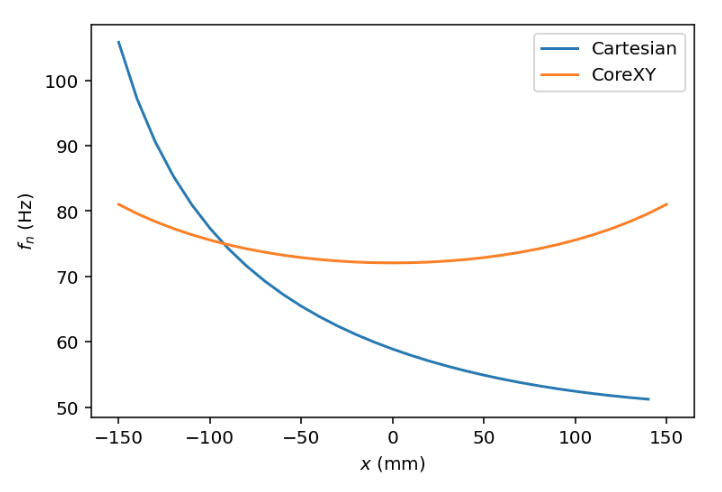
      The complication is that the spring "constant' is dependent on the spring length which changes with the position. Luckily we can measure and calculate this correction almost perfectly. Here’s a plot of how the ringing frequency theoretically changes across the print bed for a cartesian and CoreXY printer respectively. We can see how the two-belt CoreXY design balances the effect much better than a single linear-belt (with the stepper on one side) does. The linear belt design has a substantially higher spring stiffness when the print head is close to the stepper than when it’s far away and I think it’s clear that we need a positional parameter even for the CoreXY system.

      946d5504-260c-40b8-a967-2a91bedd2f34-image.png

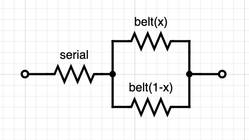
      Both of these functions are of the form sqrt(1/p) where p is a quadratic polynomial. For the cartesian case p(x) has 3 parameters of which one is the relative belt lengths for a given x-coordinate and can be easily measured. If we add other serial springs to the system (like the stepper motors and compliant mechanics) we get another simple additive term. Measuring f_n at two different positions will determine the entire system.

      513f459c-cce0-48d3-b70a-5740edf3e4db-image.png

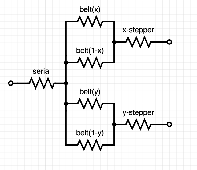
      For a CoreXY system it gets a bit more complicated since the belt lengths depend on both x and y. The compounded spring model is also a bit more complicated:

      5652fc79-9861-4152-8d6a-c9720d17a636-image.png

      For one axis, we have 5 unknown parameters: stiffness of the x and y belt respectively, the serial spring at the end effector and the two stepper springs. We can probably assume that the two steppers are identical and collapse them to one parameter, but we are still left with 4 parameters. For the other axis, many of these parameters overlap. The steppers and belts are identical with only a difference in the driven mass. The serial spring is also different. So we have a total of 6 parameters across two axes. This means that we need to measure f_n for three points per axis rather than two to determine the parameters for the system.

      One more thing. Can we calculate the spring constant from a stepper motor? The electrical field in the motor is effectively a spring, and at a static position the spring constant may at a first order be able to be calculated as the holding torque over one full step. I.e. once you exceed the holding torque the stepper will be closer to the next step 2 steps away than the current one and skip.

      My stepper's data sheet claim a holding torque of 0.43 Nm and are rated at 1.684 A. I run them at 85% max current though, so 0.37 Nm. They have a 0.9° step size, 18 tooth pulleys with 2mm pitch belt, so the radius is 5.7 mm. If I calculate correctly, this gives me a spring constant of 710,000 N/m or around 10x higher stiffness than the belts. The impact is still a reduction of f_n of around ~4 Hz though, so not insignificant. I wonder if this linear spring force calculation is valid (especially for micro stepping too) though. There is definitely a reduction in torque at speed too. How significant is that at the speeds we run at?

      posted in General Discussion
      DigitalVisionundefined
      DigitalVision

    Latest posts made by DigitalVision

    • RE: A Software Solution to Eliminate Ringing?

      Another approach that should be very straightforward for calibrating the ringing dynamic would be to attach a cheap MEMS accelerometer to the print head and log samples at different locations. Accelerometers with up to 8kHz sampling rates are less than $1 each in volume. Determining the ringing frequency should be trivial and very accurate.

      A more crazy idea: You could easily build a closed loop system with an IMU. The filter lag in an accelerometer can be as low as 1 ms, and with say 1kHz sampling we’d be well within reasonable latencies. So you could simply measure the x,y,z acceleration in real-time and compare to the desired acceleration - and apply a motion compensation signal (using the spring model) to correct for any deviation.

      posted in General Discussion
      DigitalVisionundefined
      DigitalVision
    • RE: A Software Solution to Eliminate Ringing?

      @bot a CoreXY has a more complex model, but it seems to be enough to measure 3 points per axis instead of 2. I haven't yet started to work on a position dependence model for a delta yet – and I still need to get some time to implement and test the CoreXY one. The delta geometry is more symmetric, so it may be easier to calibrate – unless the wire bundle ends up messing up things. I did get great results in the center of bed though, and I haven't yet tested how they vary with position.

      posted in General Discussion
      DigitalVisionundefined
      DigitalVision
    • RE: A Software Solution to Eliminate Ringing?

      @bot said in A Software Solution to Eliminate Ringing?:

      So, given all that, would using your method be as simple as determining the different frequencies at different parts of the axes, and cancelling as required based on position?

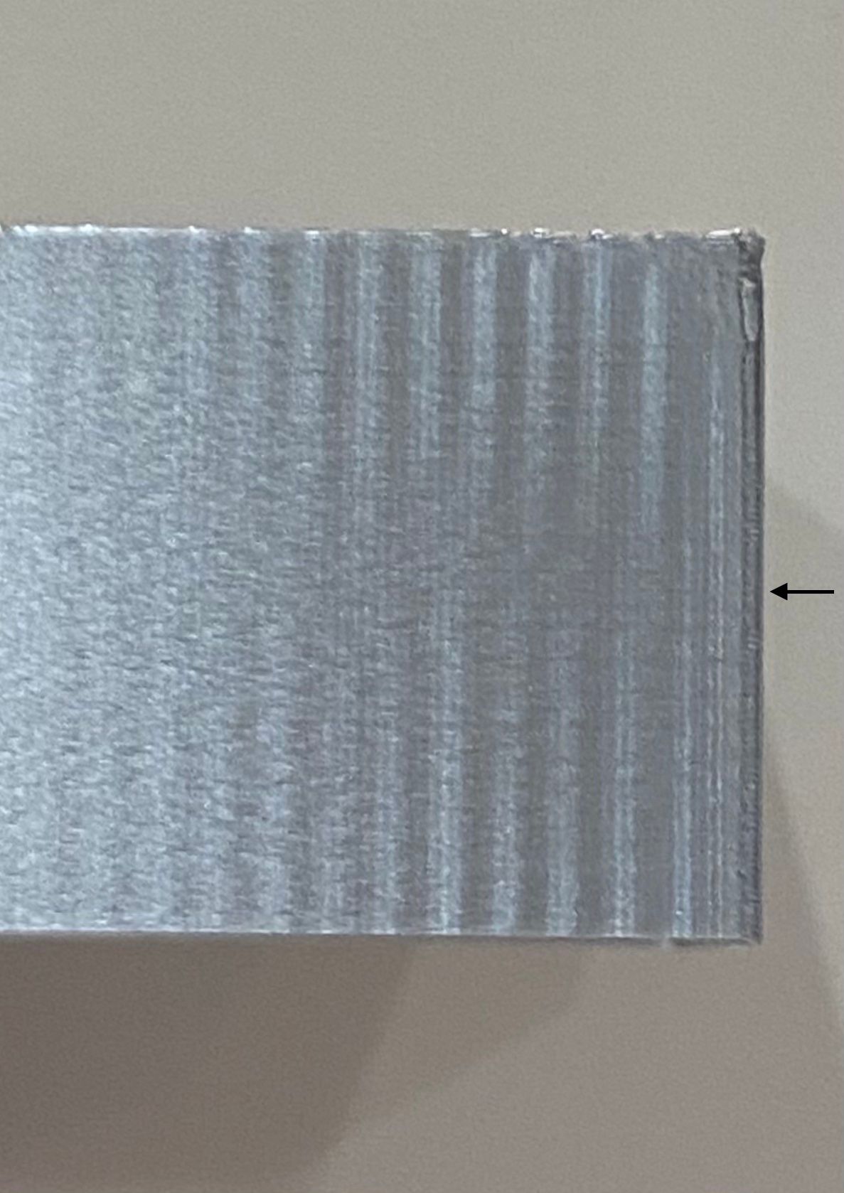
      Yes, in theory at least. For a cartesian all you would need is to determine the frequencies at two different positions per axis and provide the positive and negative belt lengths at a known location. One could probably create a nice script to automatically generate the right structures to print at the known locations. I found it most easy and consistent to spot the acceleration ringing (where the extrusion width oscillates), and especially when printing in a semi-translucent material. Here's a photo on silver filament which is very hard to capture on photo showing the phase inversion in the ringing pattern as the f_n parameter was varied across the print z. If you get it right, there is a rather sharp region without ringing that's fairly easy to spot and measure:

      IMG_8369.jpg

      posted in General Discussion
      DigitalVisionundefined
      DigitalVision
    • RE: A Software Solution to Eliminate Ringing?

      @bot said in A Software Solution to Eliminate Ringing?:

      Short length: 166 mm to 216 mm
      Long length: 970 mm to 920 mm
      X axis "worst case"
      Short length: 366 mm to 416 mm
      Long length: 770 mm to 720 mm

      Cool. Your "best" case should have up to 75 % higher spring constant than the worst side (very dependent on which side of the print was at the most extreme point). If your belts dominate ringing, this should translate into ~32% higher ringing frequency, so the good side ringing period should be as little as ~3/4 of the worse side (with the stepper motor and other serial springs the difference will be slightly smaller though). That seems possible from your photo.

      I don't know what that secondary ringing at around 2/3s of the print is though. That far too early to be at the deceleration ramp but also too late to be a late residual from the earlier corner.

      posted in General Discussion
      DigitalVisionundefined
      DigitalVision
    • RE: Stepper precision +-5%

      @mendenmh said in Stepper precision +-5%:

      @DigitalVision No, I don't have a specific model for how the torque varies with offset from the center. The graph you attached is probably a very good guess, for a motor sitting right one a step. I would expect the behavior to be more complex at (say) a half-step boundary, where the two poles are pulling equally.

      Thanks. I did a quick and very simple and crude simulation model myself and found that although the behavior was very dependent on the model parameters, it seemed feasible with the right tooth design to design a fairly flat torque curve across micro step positions if you use cos-sin phase current control. I have no idea how that trades against other aspects though and how real steppers behave.

      In work I do professionally, where such things matter, we use encoders to read the actual angles, rather than depending on any good behavior of the stepper, or gearing, or anything else. Of course, by the time we are done, one axis costs about $5000, and is accurate to 0.05 arcseconds (1/72000 degree!). Such a system lives in a room with 0.01C temperature control, too.

      That's incredibly cool.

      posted in General Discussion
      DigitalVisionundefined
      DigitalVision
    • RE: A Software Solution to Eliminate Ringing?

      @bot said in A Software Solution to Eliminate Ringing?:

      So it's safe to say we can rule out S-curve as beneficial? Or it is only beneficial with your modelling implementation?

      I'd be surprised if s-curves by themselves allow you to increase the print speed, but they will eliminate the HF transients at the ends of ramps. The trade-off is that they lead to higher peak accelerations if you want to preserve the same print time, and that means that you load the "spring" more. But s-curves allows the spring compensation model to work without requiring instantaneous position changes. And I've found this allows for substantially higher accelerations.

      I have highlighted the photo to better show what I think are signs of ringing. By my eye it's easier to see and tell that they are at least different, which supports your theory.

      Thanks, those lines help! Could you give a rough estimate of the short and long belt length for the two print locations?

      posted in General Discussion
      DigitalVisionundefined
      DigitalVision
    • RE: A Software Solution to Eliminate Ringing?

      @bot said in A Software Solution to Eliminate Ringing?:

      I think, dc42, you've been right all along that the instantaneous speed change "problem" is the one to focus on first. The last bit of HF ringing I get seems related to jerk more than acceleration, and finding a low enough "jerk" speed for sharp corners while maintaining curve speed/quality is kind of impossible.

      I personally don't think the implementation of "jerk"/instantaneous speed change as implemented in all current firmwares is very good. The purpose of jerk is to allow continuous speed through linearly segmented curves, but as a consequence you get abrupt changes (and ringing) for sharp corners too. A quick thing I don't know has been tested and I would expect to be a better heuristic would be to add a corner angle threshold and disable jerk for any corner beyond a certain angle. This is quite often used in 3D graphics as a heuristic to for when to smooth vs flat shade a 3d mesh and seems to work fairly well. You may want to mix in segment length as well in a heuristic, but in either case it shouldn't be hard to prevent "jerk" from applying to a 90° corner between two long segments.

      posted in General Discussion
      DigitalVisionundefined
      DigitalVision
    • RE: A Software Solution to Eliminate Ringing?

      @bot thanks for running this test. I must say it's hard to spot the ringing in the pictures. One thing I found useful was to limit the y axis acceleration to a very low value, say 500 while increasing x axis acceleration to a high value to avoid the cross talk. (Also make sure you've adjusted both M204 and M201).

      It seems like a good strategy for the time being (for avoiding the effects of this variation) is to simply select an acceleration value that is low enough to not exhibit ringing to any discernible amount: this way, the variation is basically irrelevant.

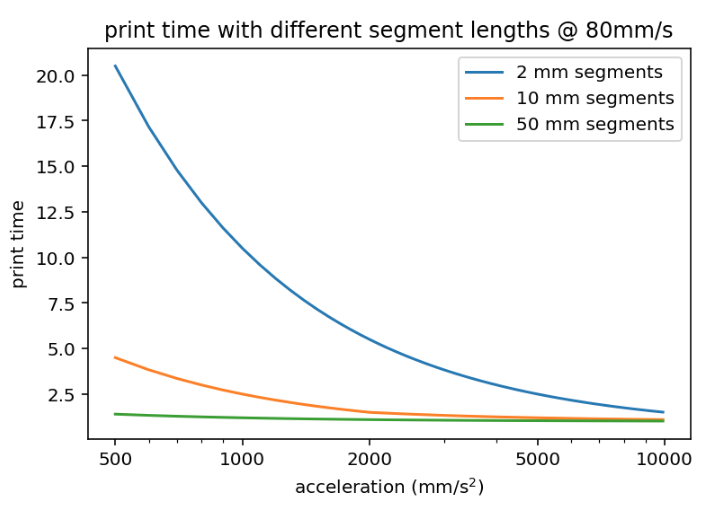
      The ringing magnitude is proportional to the acceleration so while you can mitigate it with lower acceleration settings it has the potential to affect the print time significantly, especially on print geometries with shorter path lengths. An illustration of print speed vs acceleration for different segment lengths.

      bbd84ae2-a372-45eb-97aa-b9eb02009ce6-image.png

      Do you think s-curve acceleration alone, before any cancellation of frequencies, would provide speed benefits in this regard?

      In addition to what dc42 said – the photo at the very top of this topic shows an s-curve vs linear acceleration ramp profile without any appreciable difference in ringing.

      posted in General Discussion
      DigitalVisionundefined
      DigitalVision
    • RE: Stepper precision +-5%

      @mendenmh said in Stepper precision +-5%:

      The spacing of microsteps is also very load dependent. Under no load, it is roughly uniform, but because the magnetic interaction is strongest when you are on a full step (where the metal poles exactly align), the partial steps are much springier, and more load dependent, than the full steps. That is one of the reasons people like to make layer heights on 3d printers a multiple of full steps. Using anything else can result in moiré patterns on the layering axis.

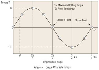
      @mendenmh, do you have a model for how the spring 'constant' varies with partial step positions? I've been assuming a roughly sinusoidal displacement/torque curve (as the figure below), modeling the region close to the stable point as a linear spring. I'd like to understand how much the slope of that region varies with the sub-step position.

      5be9a0ee-4a8b-4516-976a-1de5b98f173a-image.png

      posted in General Discussion
      DigitalVisionundefined
      DigitalVision
    • RE: A Software Solution to Eliminate Ringing?

      @bot

      So if the "short segment" is as long as possible, that is the worst case scenario?

      Correct. The belt segments get less compliant the shorter they are. If your belt's total length is 1, when you combine the two belt segments in parallel, the net compliance is proportional to x*(1-x). The maximum for this expression is at x=0.5 – i.e. the middle of the belt.

      posted in General Discussion
      DigitalVisionundefined
      DigitalVision