CNC Screw Mapping
-
I'm in the process of switching my CNC to RRF using a Duet2 and Duet Expansion Board ... and my CNC desperately needs screw mapping.
In simplest form, screw mapping is 2 (X,Y) or 3 (X,Y,Z) map lists (tables) for axis position adjustment.
From what I can tell, and I'm just getting started...
- There is no screw mapping in RRF today.
- It looks like the math can very simply be stuck in the AxisAndBedTransform and InverseAxisAndBedTransform methods in Move.cpp.
Thoughts? I'm new to RRF so this may have been asked/answered in the past.
Thanks.
-
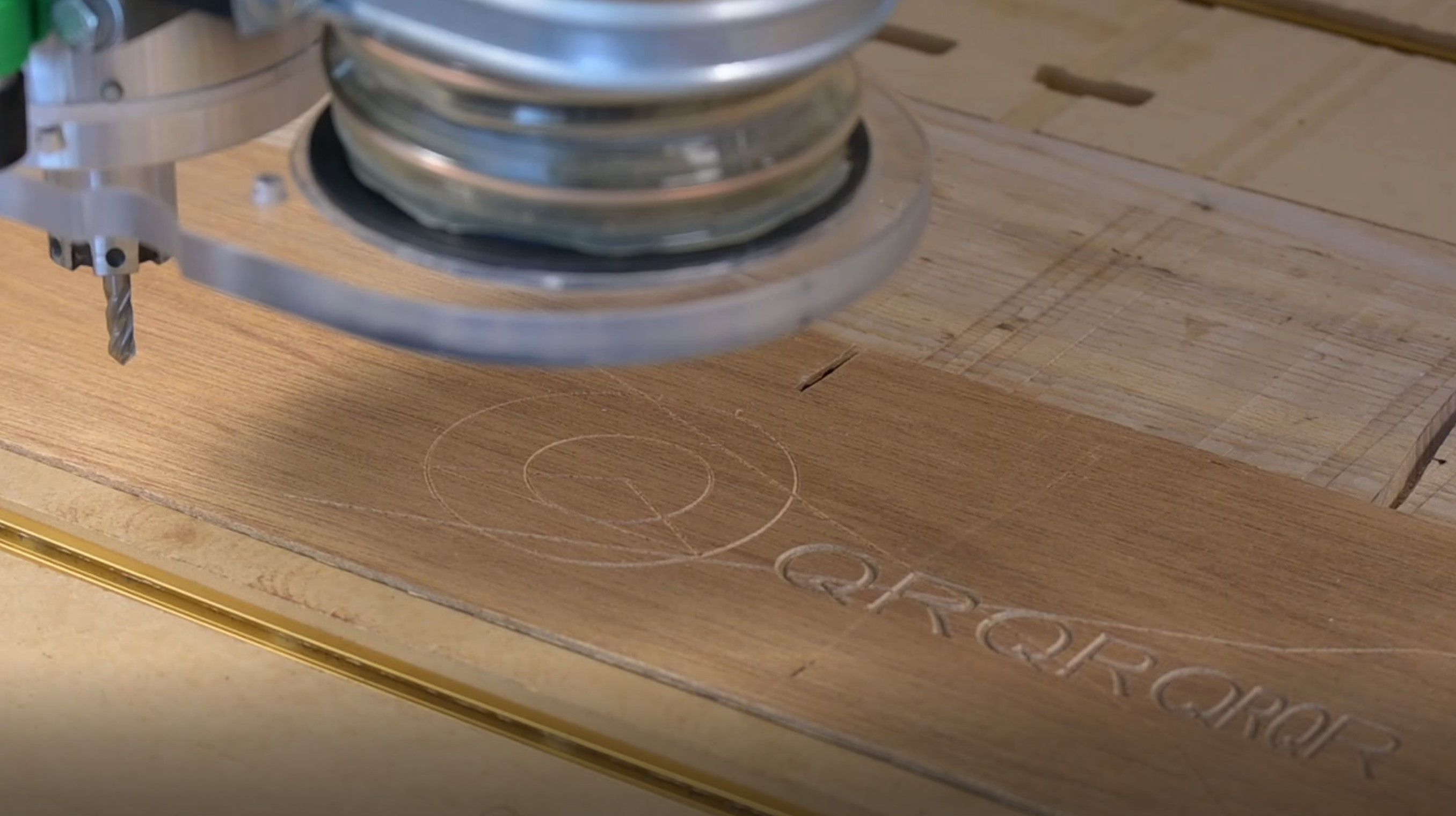
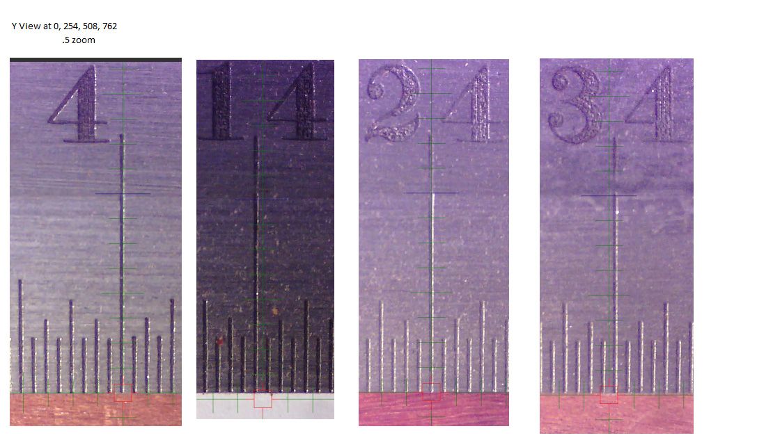
I'm going to keep working on this, and here's why... I'm including 4 photos.
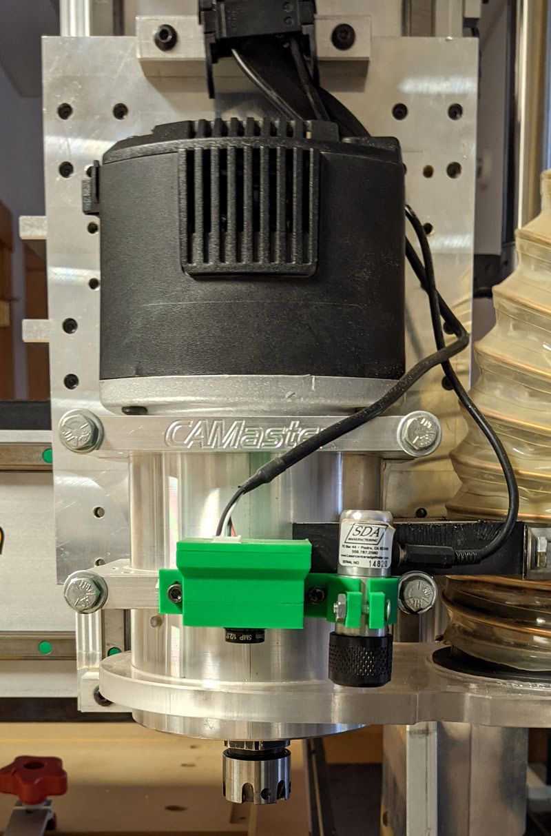
Two of them show my current CNC X axis and the camera, to understand the context. The other two show a scan of the camera looking at a ruler as I move the CNC manually in inch increments.
Looking at the problems, what is happening is that the X rails are deformed slightly in the center. The X dimension error increases then decreases (and then increases near the right edge). And .. at maximum X error there's also a Y error that's significant.
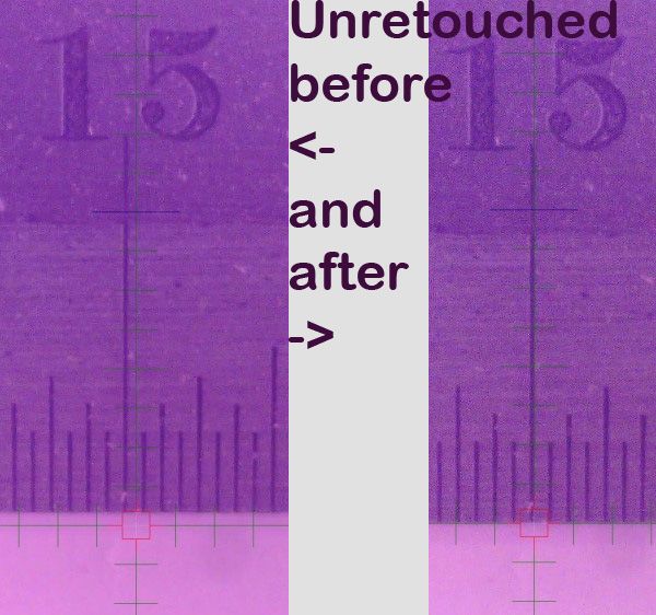
Using my last controller (WinCNC) I automatically created a multi-axis screwmap using the camera (which takes under 15 minutes) and the positioning error dropped from a max of .03" to .003".


-
The mapping seems to be working quite well.
Here's a video clip showing it in use : https://youtu.be/uTqUBrUHinU
I'll write it up in the next week or so. Note that with minor mods this could do backlash compensation.
Here's the input file:
Here's the script I run to set the screwmap
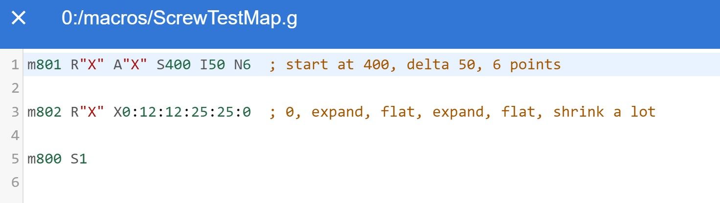
Here's the result:

Mark
-
Looks good!
Can you explain the M801, M802 and M800 commands? It looks to me that M801 and M802 are highly inter-dependent. Specifying the number of points on one and the points in the other will require additional checks that they are consistent and associated error messages, and will lead to problems if you send one of them without the other. Therefore, unless you have a good reason to use three commands, I suggest combining them into one or two commands, for example:
M801 X400:700 P0:12:12:25:25:0 ; cover X axis range 400 to 700mm, set corrections
M801 Y200:400 P0:25:25:0 ; cover Y axis range 300 to 400mm, set corrections
M800 X1 Y1 ; enable correction for X and Y axesHowever, I may have missed something, in particular I don't know what your R and A parameters are for.
-
Sure, here's the tentative syntax (from the code comment). I randomly picked the M80x's just to be easy to remember/type during debug.
--Enable/disable all screw mapping. Does not clear tables.
-- if no S prints report
M800 S[0|1]-- create a screw table for srcaxis with one row per destaxis
-- if no arguments it prints a summary report
M801 R"srcaxis" A"destaxes" Sstart Iinterval Ncount-- set screw table entries
may be called multiple times (once per row) for shorter gcode lines
-- if no data (rows) it prints contents of table
-- each entry is an offset (delta) value
M802 R"srcaxis" Xf0:f1:f2:f3... Yf0:f1:f2...
-- run the screwmap selftest (ifdef'ed just for debug testing)
M810I considered condensing the Mcode but the
destaxesis a list of possible axes that are adjusted by the source axis. So, the M802 syntax can be very very long.On my machine the X axis has 3 rows of 36 floats and the Y axis has 3 rows of 48 floats. So the M802 is a very long list of numbers. I'm not sure what the gcode limit is but this would be about 3000 characters.
I let the M802 to be called repeatedly to set rows individually for clarity.
--Mark
postscript: I'm obviously not wedded to syntax. I'd just like the script file to be readable.
There are two sets of 'upgrades' possible to the functionality for later syntax thoughts. I don't use that functionality on the CNC.
This can support directional tables (which I don't use but some milling folks do) to support directional leadscrew wear. It can also support backlash as a 1 column directional screw map.
postscript 2: in practice this works well in a script. Create a table, fill the values, create a table, fill ... The only odd error checking is to ensure the table data list is <= the defined length and the result values are monotonic. It would be easy enough to have M801 do both tasks depending on parameters but the interdependencies are worse and I think it's less clear.
-
Ok, even this M802 line is too long. There seems to be a 200 character upper limit and mine are over 300. I guess I should allow an offset in the M802 command.
-
@markz said in CNC Screw Mapping:
Ok, even this M802 line is too long. There seems to be a 200 character upper limit and mine are over 300. I guess I should allow an offset in the M802 command.
Is 200 characters not sufficient to describe the mapping for a single axis? A separate command for each axis seems reasonable to me.
-
@dc42 Thanks for all the interest. I just ran it quickly doing the following...
The worst axis is X so I copied the old lookup map from WinCNC to excel, converted to mm, then created a script file... which was too big. So, I added the O option and redid it. This worked.
I set the cnc to 116,0 (left of table), set down my yardstick horizontally.. then I disabled screw map, went to 15",0 - a known bad area) took a screen capture of the microscope view, return to 0,0 and enabled screw map then went back to (15",0) and took another screen capture.
I hadn't tried it before - and - first try with no edits. Here's the script and the comparison photo. I know it's a lot of digits, but I'm used to inches. Probably could shrink it a little.
M801 R"X" A"XY" S116 I25.4 N36
M802 R"X" X0.00000:-0.04064:0.00000:0.06350:-0.07112:-0.10922:0.02286:-0.04318:0.00508:0.10414:-0.02794:-0.09652:-0.22352:-0.40894:-0.37846:-0.47752
M802 R"X" Y0.00000:0.01778:0.06858:0.11176:0.14732:0.18034:0.22606:0.29210:0.34544:0.36576:0.40640:0.43942:0.46228:0.51308:0.53594:0.57658
M802 R"X" O16 X-0.49784:-0.27178:-0.25908:-0.29718:-0.15240:-0.24638:-0.26162:-0.05080:-0.08636:0.01524:0.14224:-0.00508:0.05588:0.09144:0.07366:0.24130
M802 R"X" O16 Y0.60960:0.59944:0.55372:0.48514:0.40640:0.30480:0.22606:0.19304:0.15748:0.09144:-0.21082:-0.48768:-0.15748:-0.12954:-0.10160:-0.08890
M802 R"X" O32 X0.25654:0.25146:0.41656:0.78994
M802 R"X" O32 Y-0.12446:-0.09652:-0.04572:0.01270
M800 S1
Photo
-
@dc42 I've forked and updated the github repo. You can see the code changes at: https://github.com/MZachmann/RepRapFirmware/tree/v3.2-screwmap
and it forks from the 3.02-dev branch (3.2 retail).
Let me know where you'd like to go from here. Implement (pull request)? Move to M-codes? Change syntax?
The only thing I couldn't yet figure out from the code base was how to correctly have the ui update the user position when the screw map definition changes.
Mark
-
Here's a doc file describing the current implementation of screw mapping.
-
I've posted a video showing a calibration run (in X). It took about 1/2 hour to gather X and Y error terms and improved the CNC accuracy from .033" to .002".
-
Nicely done!
I just had a thought, though. Make sure your yard-stick is straight. You could be compensating for an error in the yard stick.
-
Sorry, I should have posted that. You're absolutely right.
The yardstick is one of the most expensive hand tools I own since it's so important.
-
@markz Oh!!!! That's a nice "yard stick" lol!!!
-
@bot Yeah, Starrett would probably not be happy me calling it that.
-
I also spit coffee on my laptop when I saw that price.

-
I suddenly want a yard stick like that... but I couldn't even use such a large one! My print bed is only ~11" x 11". I'll look for it's younger sibling. And possibly metric, too.
-
@bot Yeah, I wish I had a metric one - if you watch the video I spend a lot of time converting inches. Kinda dumb.
backstory - when I first realized about 10 years ago my CNC had so much error I did this measurement with a normal yardstick, couldn't believe the results (especially the Y error), so in order to root-cause I had no choice.
-
I've cleaned up the code so setting a screw map entry changes the DRO readout in real-time.
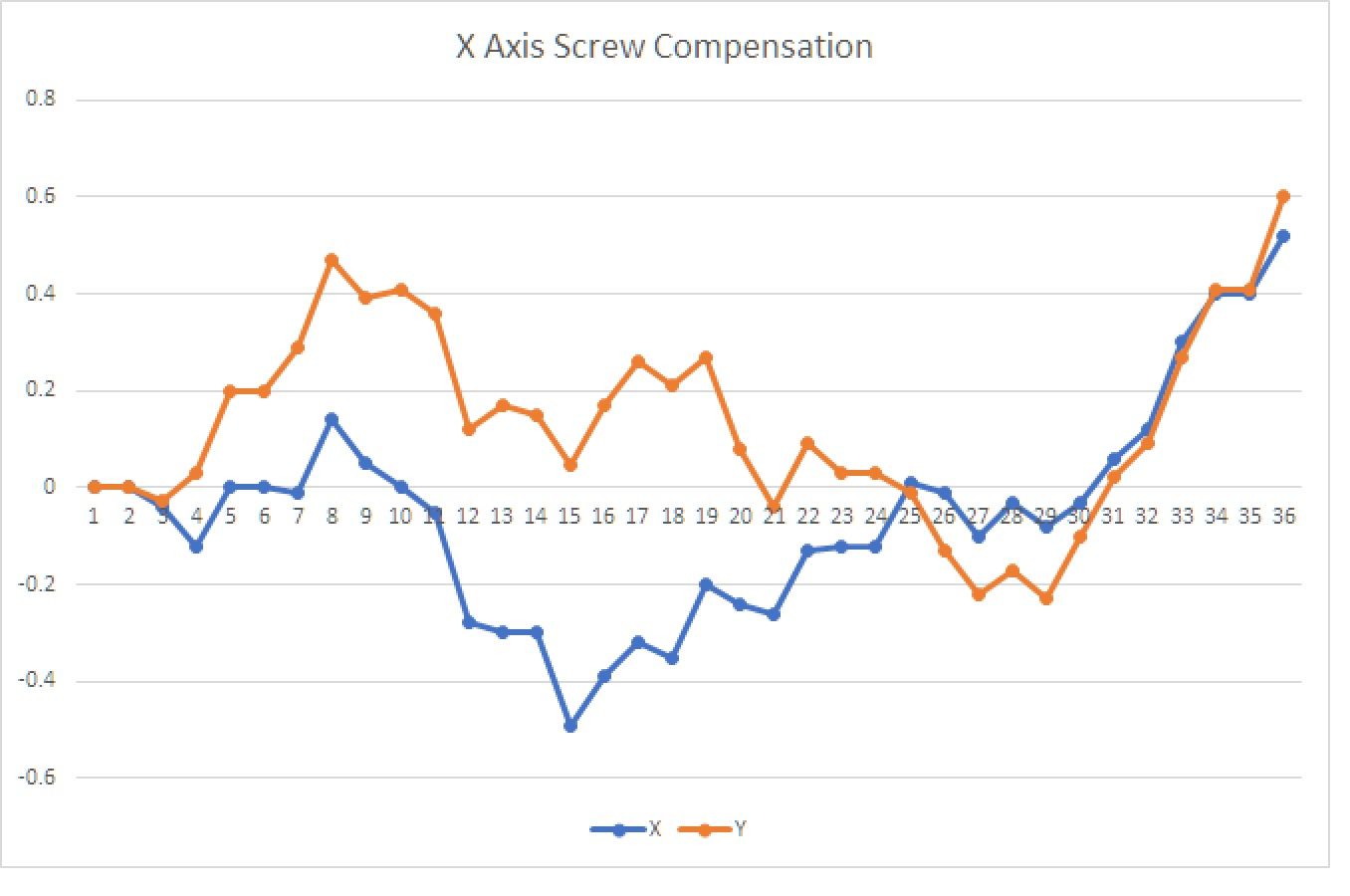
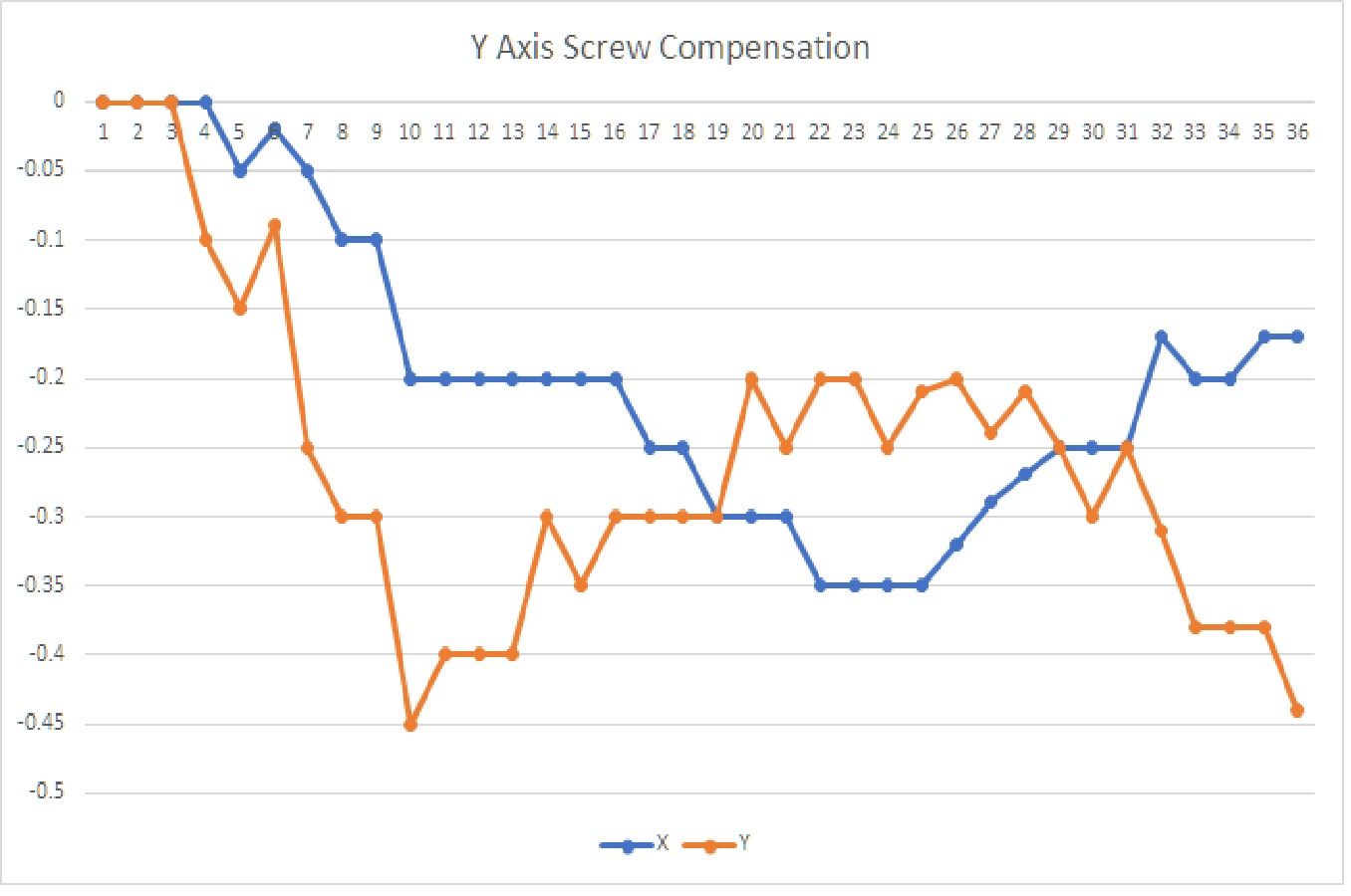
Here are a couple of plots of my CNC error curves with increment=25.4mm (1 inch). Note the 2d-ishness of the whole thing.
To put this in a worst case if I were just drilling holes the largest X error pre-compensation would be about 1.5mm (or 1/16th of an inch for US). Post-compensation error is 2*repeatability + test measurement error (~.03mm).