Smart Effector including toolboard-capabilities?
-
video_2021-02-11_00-13-44(1).mp4
We are doing some prototyping, with a regular orbiter, changing some aspects of the body.It actually is a pivot extruder, so it can rotare freely within the rod arms...
It´s not my doing, just a friend´s I am helping him to achive it
-
Looks good!
We do have plans to produce a combined Smart Effector and tool board. The main decision we need to take is how large to make it.
Duet WiFi hardware designer and firmware engineer
Please do not ask me for Duet support via PM or email, use the forum
http://www.escher3d.com, https://miscsolutions.wordpress.com -
@dc42 We are just two 3d printing fans....just doing it as a hobbie...no bussiness attached
-
@dc42 Hi, I'm the designer of the Orbiter extruder.
For delta printers you need the version with flipped gears like this one:
https://www.thingiverse.com/thing:4609940The filament path is closer to the middle of the extruder so has a better clearance towards the rods.
I designed an adapter to fit this version you can find it here:
https://www.thingiverse.com/thing:4648938The result is not the best but it works.
The upcoming V2 will be more optimized in size and would fit better to delta printers. But I have not tried it yet.
-
@Lorincz-Robert , thanks. Looking forward to the V2!
-
here is a teaser video of V2:
https://www.youtube.com/watch?v=hpvJZ1BHheM&t=2s -
@Lorincz-Robert said in Smart Effector including toolboard-capabilities?:
here is a teaser video of V2:
https://www.youtube.com/watch?v=hpvJZ1BHheM&t=2sWatching the video in the context of this thread (which is specific to the smart effector and delta printers), my impression is that the filament path doesn't seem any closer to the center of the extruder (compared to the "CR" version of the orbiter.) If the offset is the nearly the same, the same type of adapter that moves the extruder high up above the effector will have to be used... At that point, many people will prefer a full size "flying" extruder floating 40 to 50mm over the effector.
I'm also concerned about the low suggested 'jerk' suggested for the orbiter. Low jerk negatively impacts pressure advance, and more pressure advance would be needed when there's a long filament path between the extruder and effector.
-
@apak this looks very promising, is there any way to follow your progress on this project? like a thingiverse page or a forum thread?
-
@Hergonoway It´s not my doing...I am just a part of it as I "consultant". The guy doing it might do some tweaks, but He is planning on a whole differnt design for a direct extrusion for smarteffector. He is up to date with this thread so He might post something
-
We'll hold fire on designing a combined Tool Board/Smart Effector until we know what rod spacing we need to use to accommodate an extruder mounted directly on it. I think it will be around 80mm, but we really need to know extruder dimensions to be sure.
-
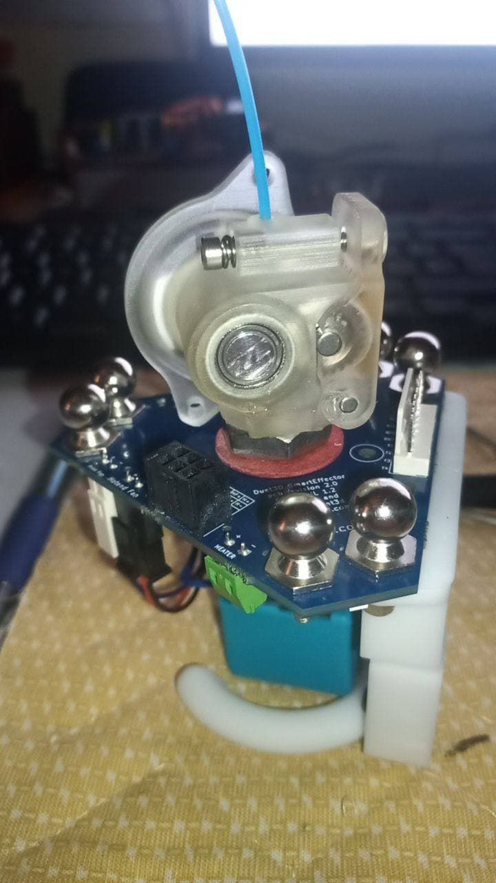
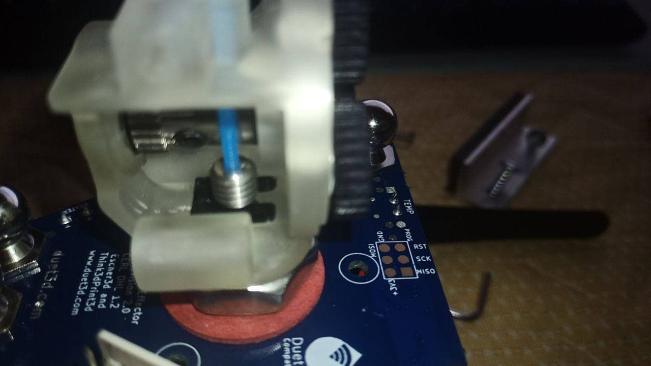
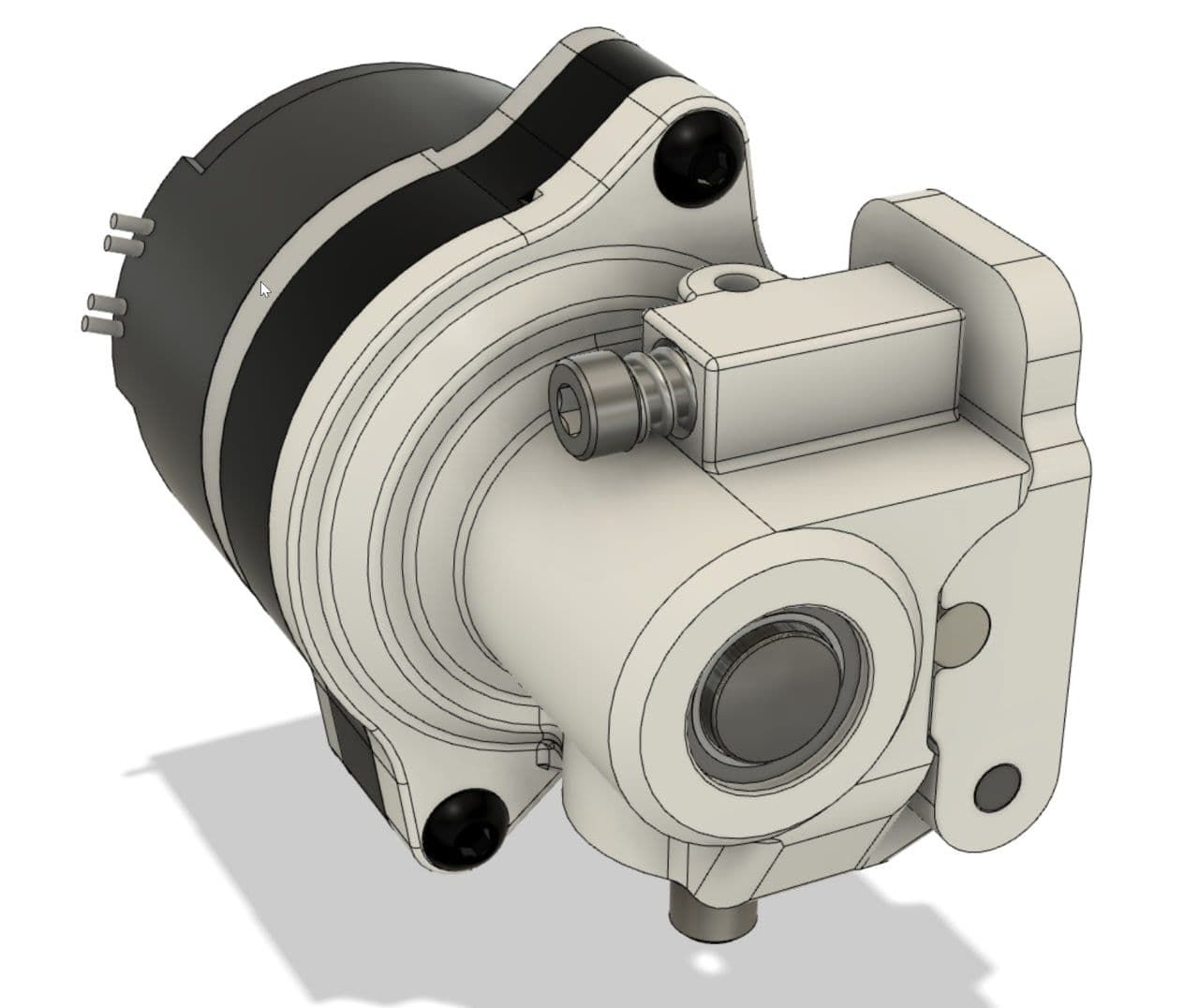
This design work's pretty good an the rod spacing is 64 mm. Do you need the step file?

-
@mrac1 said in Smart Effector including toolboard-capabilities?:
This design work's pretty good an the rod spacing is 64 mm. Do you need the step file?
That would be nice. That doesn't look quite like the orbiter - is it something you designed? Any information you can provide to replicate would be very useful.
I'm desperate to replace the nimble I'm using on my smart effector. I'm actually considering going back to a titan extruder, pancake motor, and piezo all hanging from a non-smart effector.
"I'm not saying that you are wrong - I'm just trying to fit it into my real world simulated experience."
-
@mrac1 I'd be glad if you could provide the step file. I'd like to try something with the dc42's 80mm assumption base on your model.
I've got 2 questions:
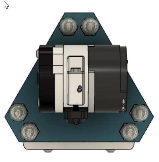
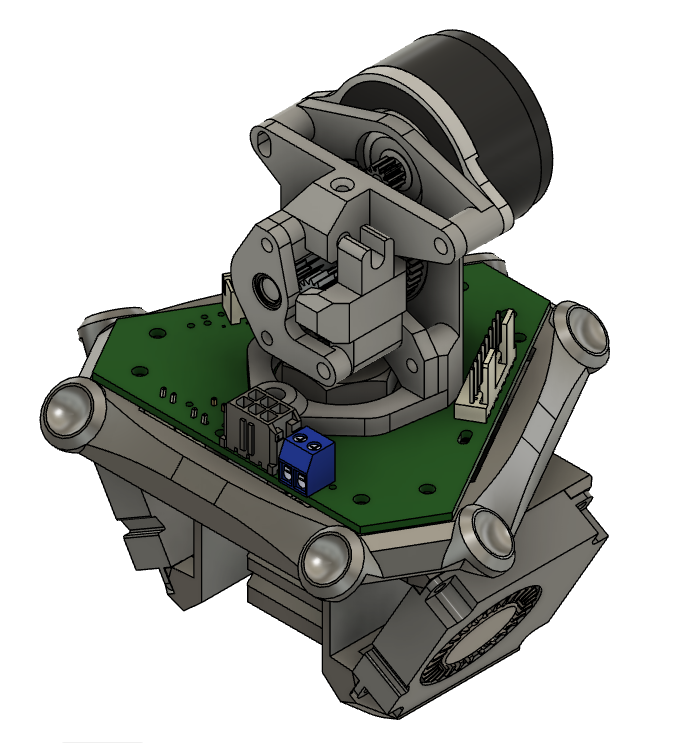
- why did you choose this ball stud placement? Wouldn't it been easier to "just" offset the ball studs from the smart effector set horizontally to reach the desired clearance? Maybe it's just for the design aspect, or because of the top heater connector but I have to ask
")
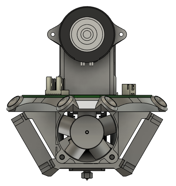
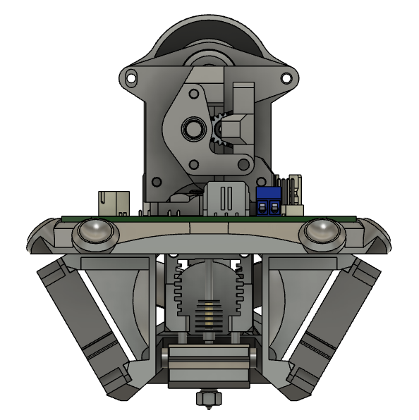
- what's your feedback with this 2x4010 blowers configuration? Main issue with a smart effector and a mosquito is the vertical clearance to play with while keeping a good airflow distribution.
Delta goes BrrrRRRRrrrrrRRRRrrr
- why did you choose this ball stud placement? Wouldn't it been easier to "just" offset the ball studs from the smart effector set horizontally to reach the desired clearance? Maybe it's just for the design aspect, or because of the top heater connector but I have to ask
-
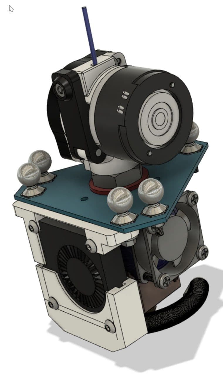
@garyd9 Yes, it's my own design. Here is the step file: https://1drv.ms/u/s!AnpMmSRyS0cUkJ94Y0O-LqHwrEh7RQ?e=yLTPwj
-
@Hergonoway the 64 mm rod spacing comes from my first design without smarteffector: https://www.thingiverse.com/thing:3609378
And yes, it should also look as good as possible")
The two 40x10 fans work extremely well! However, it also took many attempts until the air flow was right.
-
@mrac1 said in Smart Effector including toolboard-capabilities?:
@garyd9 Yes, it's my own design. Here is the step file: https://1drv.ms/u/s!AnpMmSRyS0cUkJ94Y0O-LqHwrEh7RQ?e=yLTPwj
I'm impressed. That's a nice compact design, and looks printable without too much problem. 5:1 ratio? Are all the parts (gears, bearings) out of a BMG extruder?
If all the "guts" are BMG parts, I might have to order one and try that for myself...
Thank you
Gary -
@garyd9 Yes, all parts are from the BMG, and the ratio is 5:1. You also need M3/M2.5 screws and M3 brass inserts. Version 1.0 is without brass inserts and is still in use on my two deltas.
-
@mrac1 said in Smart Effector including toolboard-capabilities?:
@garyd9 Yes, all parts are from the BMG, and the ratio is 5:1. You also need M3/M2.5 screws and M3 brass inserts. Version 1.0 is without brass inserts and is still in use on my two deltas.
Can you tell me what values you use for M92 (steps/mm), M201 (acceleration), and M566 (jerk) with that extruder? How is the print/extrusion quality?
I might alter your model in two ways: First, I actually prefer using nuts (or even better: lock nuts / nylocks)to brass inserts when feasible. I once had a brass insert pull out, but I've never had that happen with a nut. Second, I'm thinking about modifying the "FilamentGuide" part to remove some plastic in order to make the BMG plastic wheel/gear a bit more accessible for manually turning it.
Thank you for sharing your design!
Take care
Gary -
@garyd9 Print quality is a bit better than my Prusa MK3s.
There isn't much room for nuts and my first version, as I said, simply screws directly into the plastic.
Here are my values:
M350 X16 Y16 Z16 E16 I1 ; configure microstepping with interpolation
M92 X200.00 Y200.00 Z200.00 E709 ; set steps per mm
M566 X1200 Y1200.00 Z1200.00 E600.00 ; set maximum instantaneous speed changes (mm/min)
M203 X18000.00 Y18000.00 Z18000.00 E4800.00 ; set maximum speeds (mm/min)
M201 X3000.00 Y3000.00 Z3000.00 E4000.00 ; set accelerations (mm/s^2)
M204 P1250 T3000 ; set print and travel accelerations (mm/s^2)
M906 X1000 Y1000 Z1000 E370 I40 ; set motor currents (mA) and motor idle factor in per cent -
@Hergonoway said in Smart Effector including toolboard-capabilities?:
- why did you choose this ball stud placement? Wouldn't it been easier to "just" offset the ball studs from the smart effector set horizontally to reach the desired clearance?
I've been playing around with the model to see what it might take to get it to fit well on a smart effector. The 64mm spacing that @mrac1 is using does work, but I don't know if that's the "best" solution.
Also, there's more to arm spacing than just the gap between two parallels arms: there's also the gap between the "centers of articulation" (as described here: https://reprap.org/wiki/Delta_geometry#Effector_stability and referenced there as "b".) From that page, there's a theoretical relationship between effector stability, the arm spacing, and "b".
For reference, @dc42's smart effector has an arm spacing of 55mm, and a "b" of 12mm. Using the formula provided on that linked page (Tilt Effector Stability = (Arm space)²/b), the smart effector has a "TES" of ~252.08.
Assuming that theoretical work is accurate (or close to accurate), the effector from mrac1 has a much lower stability of ~134.94. (64^2 / 30.354)
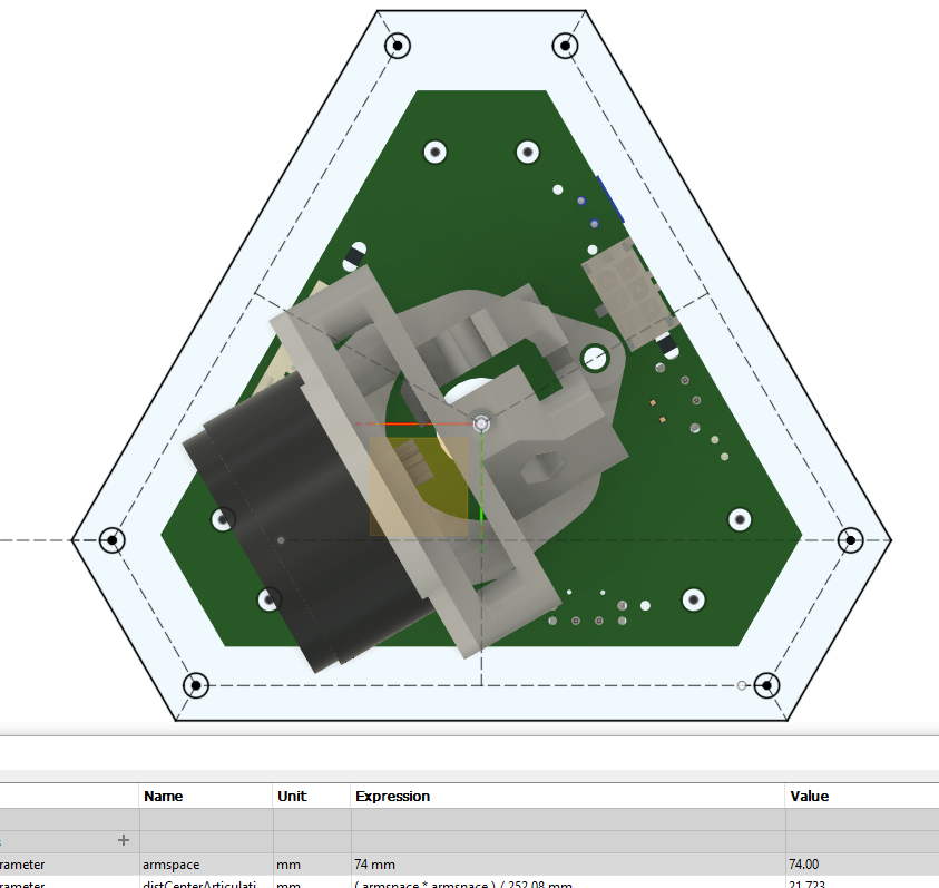
From that, I started playing around in Fusion360 modeling arm spacing, and set thing up so that the "b" value is computed automatically based on the arm spacing in order to maintain a "TES" value of 252.08. (I just force the "b" value to be "( arm space )² / 252.08 mm.") Then I linked mrac1's excellent extruder model on top of the resulting sketch and kept adjusting the arm space until the arms (and arm movement) was completely clear of the lines connecting all 6 ball joints. (My choice of clearance was somewhat arbitrary. Some delta builds would need more space, and others would need less.)
Here's what it looks like with an arm spacing of 74mm. In this case, "b" is 21.72mm.
Note that this is pushing it really close. Here's a snippet showing 80mm (with "b" of 25.39):
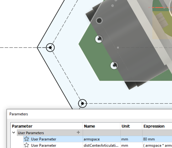
So, at 80mm arm spacing, there's more wiggle room, but on some delta geometries where the print area is actually larger than the triangle formed by the X/Y/Z verticals (and therefore carriages), even this might not be enough. (I think some SeeMeCNC machines are like that.)
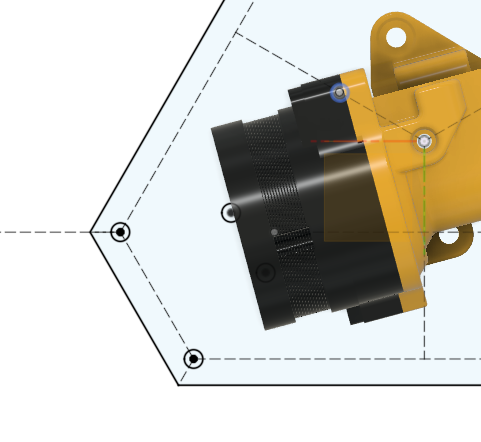
I also put the "CR" version of the Orbiter on my sketch to see how that would fit. Specifically, I used the "CR" version of the oribiter. This specific version has a more centered filament path compared to all other available/published versions. (The "v1.5" that's available for sale would stick out an additional ~9mm.) I rotated the model for what I perceived to be the best fit (with 80mm arm spacing):
One important difference when comparing the orbiter and mrac1 extruder pictures above is that they are shown with different stepper models (when they actually use the same one.) According to LDO specs, the stepper should have a total thickness of 17.5mm. The model with the mrac1 pictures has a 20mm thick stepper and the orbiter model as a 17.0mm thick stepper.
Another important difference that isn't shown at all in these pictures is the vertical height of the stepper. (Due to delta arms and angles, this is important for determining clearance.) The mrac1 extruder has the stepper centered 39mm above the effector. The orbiter extruder has the stepper is centered 18mm, PLUS the height of any adapter, above the effector. (It might also be possible to modify the orbiter model to not need any adapter.)
Hopefully all this typing and snipping is useful to someone.
Take care
Gary"I'm not saying that you are wrong - I'm just trying to fit it into my real world simulated experience."