Designing a PWM to Analog mini board for fans
-
Ill get a hand full if Brexit is not going to make shipment to Germany crazy expensive. Are you heading for SMD or through hole components?
This is not only super convenient for Fans but i will use this analog voltage to control some LEDs with an Arduino Nano
Custom ANET A8
Custom Delta: D-PATCH (Delta Printer with Automatic Tool CHanging) https://forum.duet3d.com/topic/16082/d-patch?_=1596131234754All I do here is under this license: CC BY-NC-SA
-
Thanks @taconite! I'm going for smd, but not crazy difficult to solder (just 0805, soic8...) Depending on how many people want some boards and their ability to solder smd, I can offer sending boards already populated with smd components.
Regarding controlling leds, why don't you directly feed PWM to the leds? If your PWM frequency is high enough, you can't see the flicker at all...
-
@taconite also remember the current limits... I don't think this kind of circuit is good for more than ...200mA? The BJT will dissipate quite a bit of power by itself at moderate currents, but it depends too on supply voltage (5V would draw much less power).
-
I thing I'll leave and option to feed the opamp/transistor with an external power, using something like that:
so you can jumper select the power supply.
Thoughts?
-
Ok, I had a spin at the schematic. That would the plan:
INPUTS:
PWM+
PWM-
GND
Optional V_EXTJUMPERS:
V_ANALOG (PMW+ or V_EXT)
HALVE_IN (shorted=yes)
SCALE_OUT (shorted = no)OUTPUT
Analog V_OUTEXPLAINING
Duets use PWM+ as V_FAN, PWM- as pwm'd ground.
With HALVE_IN open, SCALE_OUT closed, VOUT follows PWM input up to V_FAN-0.6V. Rise time is about 140ms.You can use a external step up converted (1€ in Aliexpress for a 28V 2A max) connected to V_EXT and then select jumper V_ANALOG to V_EXT and get max fan voltage. With just one step up you can feed many fans.
You can also connect an external (arduino?) PWM voltage to PWM+ with any voltage and any power supply to V_EXT, and output would follow (3.3V, 5V, 12V...) You cannot use a PWM+ voltage greater than V_EXT. If you set HALVE_IN short, input is automatically halved, so you can use a 24V PWM+ with a 12V V_EXT, for example.
And last, if you short jumper SCALE_OUT, PWM+ voltage will be ignored and V_OUT will be PWM % of V_ANALOG.
This is the schematic for reference:
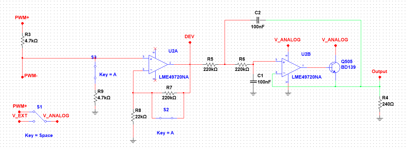
It would use a dual smd opamp (TLV9352, 0.7-1€ ) some resistors/capacitors (smd 0805, ~cents), a through-hole mid-power BJT (like BD139, ~0.5€) and some jumper pins, plus board (less than 1€) and shipping costs for everything. The transistor must be heatsinked for any significant current.
Does it sound interesting? Would you get some of this boards?
-
@Egon-Net said in Designing a PWM to Analog mini board for fans:
I think I haven't understand you correctly. You use the PWM+ wire from Duet. In the base design you use both PWM+ and PWM- (they are called Fan+ and Fan-). Duet's do the PWM on the ground side (PWM-), so you can use any voltage for the fan.
What I mean is that the duet uses a low side transistor and common (+) connection, with this design, the transistor is on the high side and the fans have common (-) connection.
-
@Egon-Net said in Designing a PWM to Analog mini board for fans:
VOUT follows PWM input up to V_FAN-0.6V
How did you calculate this? Supply voltage - 0.6V VBE for Q505?
Do you assume that the U2B output can go all the way to the V_ANALOG voltage? This is not the case with most op amps. Did you verify that this is indeed the case?
Changing the design to use a non emitter follower configuration may eliminate the need for the OPAMP to go all they way to the rail voltage. Can be a PNP on the high side or NPN on the low side (or P or N channel respectively if you prefer mosfets).
(I am not an EE so please take it with a grain of salt).
-
is this all necessary ?
did you try just adding capacitor in parallel with the fan to reduce whining ?
duet also allows changing pwm freq . i think with a bit of freq tuning , adjusting min/max duty cycle and simple capacitor should solve all those issues without extra circuits . -
@hackinistrator said in Designing a PWM to Analog mini board for fans:
did you try just adding capacitor in parallel with the fan to reduce whining ?
I think it's necessary since nothing prevents the capacitor from always getting charged to max voltage.
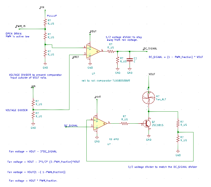
Here is a design idea, it's incomplete but demonstrates the principle. It uses low side transistor (a NCHAN mosfet would be a better choice IMO), to keep the common fan control model, is not penalized by VBE dropout, and relaxes the rail to rail requirements of the opamp. It can work with split vin/vout supplies or can be simplified to support a single supply.
This is just an idea, not a complete design and may require some capacitors and other stuff for stabilization, a led or two for diagnostics, a fuse (?), and so on.
(I am not an EE so please take this with a grain of salt).
-
@zapta said in Designing a PWM to Analog mini board for fans:
@hackinistrator said in Designing a PWM to Analog mini board for fans:
did you try just adding capacitor in parallel with the fan to reduce whining ?
I think it's necessary since nothing prevents the capacitor from always getting charged to max voltage.
Here is a design idea, it's incomplete but demonstrates the principle. It uses low side transistor (a NCHAN mosfet would be a better choice IMO), to keep the common fan control model, is not penalized by VBE dropout, and relaxes the rail to rail requirements of the opamp. It can work with split vin/vout supplies or can be simplified to support a single supply.
This is just an idea, not a complete design and may require some capacitors and other stuff for stabilization, a led or two for diagnostics, a fuse (?), and so on.
(I am not an EE so please take this with a grain of salt).
Now I get what you mean about the common(+), you meant the output side! I thought it was about the input side, that's why I didn't get it. Now, entering your circuit:
I can see two stages, first one is a rail to rail comparator, resistive halver, and a single pole low pass filter. It's a valid one, but I'd prefer to use an opamp (from the dual opamp IC) so I don't have another IC. I also prefer a second order lowpass (it has better ripple/settle time), but I see no problem in your approach (other than that you loose PWM magnitude/active high compatibility).
It is the second stage that worries me: you have used a positive-feedback opamp configuration, relying in the BJT inversion, instead of using negative feedback. I'm afraid it could be unestable because of the delay in the feedback though the inverting BJT. And you would need a diode between the opamp and the BJT, since the opamp would not be able to reach GND flat, but that's no problem.
Let me have a look at your circuit and do some simulations. All in all, I like your feedback because this is a topology I didn't think about, and it's interesting (I'm so biased to analog audio circuits!)
I'll return one I have done some test!
-
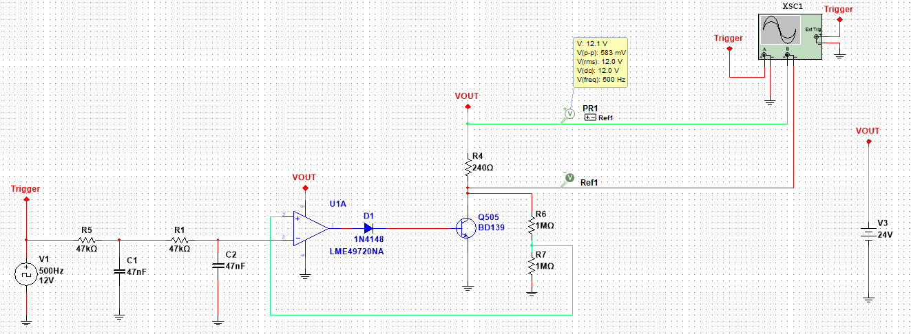
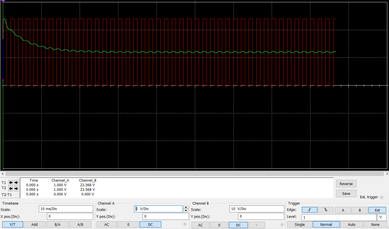
I just simulated the second stage of your circuit, and it's quite prone to oscillating, even with an ideal opamp... I should test the real thing to be sure, maybe we run out of phase margin with the BJT capacitance in the feedback loop. Besides that, I don't really belive my simulation results, it tells me I get full 24V into the load when at least a Vce-sat (~0.2V) should be lost in the BJT.
Also, it's only valid for a rail to rail signals, since it inverts the input and any less of rail to rail would float from +VCC... So we lose the capability of tracking PWM magnitude... Do we really need it?
I'll post again when I build a protoboard with the circuit.
-
@hackinistrator said in Designing a PWM to Analog mini board for fans:
is this all necessary ?
did you try just adding capacitor in parallel with the fan to reduce whining ?
duet also allows changing pwm freq . i think with a bit of freq tuning , adjusting min/max duty cycle and simple capacitor should solve all those issues without extra circuits .It's not just whining, lots of fan don't even work, or lose all speed in 99% PWM already.
Also you can change frequency in the Duet's, but not in de Duex.
A capacitor does nothing by itself, because the charge/discharge would not be controlled, so it would range from not doing anything at all, to override PWM an making the fan work at 100%. Believe me, I've tinkered a lot before I decided to go this route. -
@Egon-Net, your analysis of the circuit is correct. A couple of notes:
-
The only rail to rail requirement in this design is the output of the first amplifier. It's easy to achieve that with a comparator since they don't need to be linear and can just saturate the output transistor.
-
For the off condition of the power transistor, instead of a diode you can use a resistor between base and emitter such that VBE is below the cutoff voltage when the op amp is at its lowest output value.
-
Stability and dynamic behavior is above my pay grade. When something oscillates I just stick capacitors.
") (I am not an EE).
(I am not an EE). -
I don't think we can about the magnitude of the input signal, just about its duty cycle and the comparator preserves that.
-
I would also add a resistor in parallel to the fan such that the circuit provides the correct output voltage also without load.
-
What simulation software do you use? Looks nicer than the freebies I could find.
-
-
@zapta said in Designing a PWM to Analog mini board for fans:
@Egon-Net, your analysis of the circuit is correct. A couple of notes:
-
The only rail to rail requirement in this design is the output of the first amplifier. It's easy to achieve that with a comparator since they don't need to be linear and can just saturate the output transistor.
-
For the off condition of the power transistor, instead of a diode you can use a resistor between base and emitter such that VBE is below the cutoff voltage when the op amp is at its lowest output value.
-
Stability and dynamic behavior is above my pay grade. When something oscillates I just stick capacitors.
(I am not an EE). -
I don't think we can about the magnitude of the input signal, just about its duty cycle and the comparator preserves that.
-
I would also add a resistor in parallel to the fan such that the circuit provides the correct output voltage also without load.
-
What simulation software do you use? Looks nicer than the freebies I could find.
My notes to your notes
")
- The opamp I was going to use (TLV9352) is even more rail to rail (50mv from rail at 10K IIRC) than that comparator, so I can go with the comparator 1st stage without adding a second IC
- I don't think so. I will simulate it, but I think it will only force the opamp to source more current, and not improve the off state of the BJT, but I may be wrong. A diode forces 0.6V voltage drop irregardless of the current. Any suggested resistor value to try?
- I am myself an EE, but not working as it, so I'm quite rusty. But I've been doing a lot of DIY audio stuff design, and I'm very used to opamps oscillating because of the feedback loop/load capacitance/whatever. Analog electronics is "fun" XD
- Yes, I agree losing magnitude is a good deal for going rail to rail. U can always chose a external supply to scale to your heart's desire.
- I agree. I already thought of that, and it will be present in the final version.
- I use National Instruments' Multisim since my early years as a Comm/EE student
As soon as I can check stability is not a problem, I will design the final schematic and go to the PCB phase
-
-
I'm also in, I've used a small normal rectifier I've found on the internet with a capacitor and whatnot, but I'm still interested.
Portugal based here btw.Also one note on the fans, they work from 8v to 24v most of them so, would be nice to develop the board to have that range?
Regards!
-
1 The TLV9352 looks good indeed.
2 Since the TLV9352 can go to 50mv, a VBE resistor may not be needed. If needed, you can make it, let's say, 1/2 of the output resistor, this way once the op amp output gets to 3x0.7V, the current through the VBE resistor will be fixed and any current increase will go to the base.
3 My formal EE education is from a vocational high school so not that deep. I watched though some stability videos on youtube recently and start to grasp the concept. https://www.youtube.com/watch?v=-CS5th2zKWY
6 I tried multisim two days ago, it was very easy to use but I didn't see much of a part library, maybe because I used the free version. I then installed LTSPICE which is more rough but very popular.
-
Hi again!
I got the Tina-TI model of TLV9352 opamp and simulated the circuit as faithfully as I could. Depending on the input, I can get it to oscillate, but a capacitor in the feedback loop seems to get rid of the oscillation. Now, worst case just rings (when I apply a fast rising clock direct to opamp input, not real use), so I'll put the capacitor in the PCB and test with and without the capacitor.
Using the opamp model, there's no need for a VBE resistor (you where right @zapta) and max voltage is 23.82V (which is a beliebable output). Tina seems to simulate better than Multisim.
I just ordered the components for a 10 boards test batch (since I needed to order some components for other project). I'll order a PCB batch too, and report, but will take 15 day the less for the PCB to arrive.
I think is time to count how many board you all will need:
PWM signal support:
- Open drain active low (Duet), 20k impedance
- VCC level PWM (0.05·VCC to VCC with 10k impedance or 0.1·VCC to VCC 20k impedance)
Output
- Scaled %PWM from VCC
- VCC range: 4.5V - 40V
- Current depends on power transistor, planned BD139
Are you interested in single PWM board or dual(more?) PWM board?
-
Now that I read my own post... When I talk about VCC level PWM, 0.05·VCC, I mean that "high" level can be as low as 0.05xVCC, thats 1.2V for 24V VCC, and as high as VCC itself. Low level shoud be 0V.
-
@Egon-Net said in Designing a PWM to Analog mini board for fans:
Output
- Current depends on power transistor, planned BD139
Does that mean, the user can decide on his own power transistor/fet (NPN) as long as you don't exceed the maximum Current suitable for the PCB-traces (or maybe even strengthen them with solder if necessary)?
Maybe a single board may be sufficent for most users. Is it possible, do design a dual board, that can be "cut" in two indipendent halves by the user?
If thats not possible i think it would be good to have dual boards (only).Im willing to be a beta-tester for the boards (having a watercooled toolhead with oversized loud 120mm 3-wire-fans on the radiator).
I would also be interested in up to four (4) dual boards or five to six (6) single boards of the final version./Julien
-
@ZipZap said in Designing a PWM to Analog mini board for fans:
@Egon-Net said in Designing a PWM to Analog mini board for fans:
Output
- Current depends on power transistor, planned BD139
Does that mean, the user can decide on his own power transistor/fet (NPN) as long as you don't exceed the maximum Current suitable for the PCB-traces (or maybe even strengthen them with solder if necessary)?
Maybe a single board may be sufficent for most users. Is it possible, do design a dual board, that can be "cut" in two indipendent halves by the user?
If thats not possible i think it would be good to have dual boards (only).Im willing to be a beta-tester for the boards (having a watercooled toolhead with oversized loud 120mm 3-wire-fans on the radiator).
I would also be interested in up to four (4) dual boards or five to six (6) single boards of the final version./Julien
Well, the board is not designed for high currents, but the transistor will limit the current well before the pcb traces would. BD139 IIRC has a thermal resistance of 100ºC/W, and a maxtemp of 150ºC, so it would be ok for currents about... 200mA at 24V with light heatsinking (by heart). And the limit is about disipated power, so if you can lower VCC, you would be able to use higher currents. And sice the transistor footprint is just 3 holes, you could always try different transistors if you want