Smart Effector including toolboard-capabilities?
-
@garyd9 Can you post your Fusion360 files? I've got all the bits and bobs here and wouldn't mind giving this a go to replace my nimble with the mods you made to the D3E.
-
Sure thing. I'm not sure how complete the fusion360 export is, but the plastic parts to print are in the main component.
For just the extruder, you need "idler lever", "motor mount", "front bearing idler bracket" and "filament guide."
If you use my modifications to the parts, the motor mount requires 0.5mm thick M3 washers to be between it and the smart effector (one for each screw.) (The original model from mrac1 had spacing built in.)
Assuming Fusion360 parameters are intact in the archive file, "BearingHoleDiameter" can be made slightly larger than 8.1mm. I found this was needed when I printed in ABS, as the bearing holes were too small (and forcing the bearings in would damage the ABS.) I used 8.3mm for ABS and the resulting post-print holes were ~7.9mm (which gave a nice snug fit for the 8mm OD bearings.)
"BrassInsertDia" and "BrassInsertIndent" slightly change the 2 holes on the bottom of the motor mount where the brass inserts should go. The intention was to allow me to better line up the inserts. It didn't work out very well.
The remaining parameters relate to the "effector adapter" piece. ArmSpacing is self explanatory. DesiredTES relates to the "TES" parameter I discussed earlier in this thread. MagBallMounting parameters should probably be left as-is. One is how big of a hole for the magball thread, and the other is how much flat space is needed to secure the magball.
The "PTFE Size Guide" is intended to be printed and placed on your smart effector (assuming the enter heatsink/hotend is assembled and attached.) Then put a piece of 4mm OD PTFE tubing through the smart effector into the heat sink as far as it'll go. Thread the size guide on top of that, all the way against the smart effector. Cut the PTFE tube flush with the top of the size guide, and it should be within 0.5mm of perfect.
Finally, please forgive the absolute mess I made of the fusion360 project. I'm hardly fluent with it, and sometimes I just kind of shove things together and hope they work.
")
Here's a link to the fusion360 shared from my google drive: https://drive.google.com/file/d/1d7YBo-knfZ-HGiYp8PYGQUGXExMkRIlC/view?usp=sharing
-
@garyd9 Awesome, thanks a lot. I'll give it a go this week. My setup looks a bit similar to yours, I've got hayden's magball arms too. I'll have to rework some carriages for the new spacing but that shouldn't be too bad.
-
So I found 2 other projects very closed from the D3E that I'm going to add to my current fusion360 D3E-WIP in order to eventually find new structural ideas that could be merged or refactor from.
#1: the sherpa mini: https://github.com/Annex-Engineering/Sherpa_Mini-Extruder
#2: HextrudORT (no yet available)
https://www.youtube.com/channel/UCQB3-0PIEN_wn-932h0LNOw
-
@Hergonoway said in Smart Effector including toolboard-capabilities?:
So I found 2 other projects very closed from the D3E that I'm going to add to my current fusion360 D3E-WIP in order to eventually find new structural ideas that could be merged or refactor from.
#1: the sherpa mini: https://github.com/Annex-Engineering/Sherpa_Mini-ExtruderWow, that sherpa mini certainly appears to share a common ancestry with mrac1's extruder. I don't know which one came first, but having so many similarities allows people like us to enjoy the advantages of both.
For example, the sherpa mini really has no way to attach to a smart effector without an adapter. mrac1's design has that "built in." The sherpa design has a nicer (more constrained) filament path around the BMG gears. Oddly, the sherpa design might actually be heavier than mrac1's because it has so many more walls. (Of course, that could also make it stronger.)
I'll have to import the sherpa mini STL's into fusion360 to do a better comparison, but I honestly believe having two different designs that are so similar can give us the advantage of cherry picking the best from both.
-
@garyd9 said in Smart Effector including toolboard-capabilities?:
Wow, that sherpa mini certainly appears to share a common ancestry with mrac1's extruder. I don't know which one came first, but having so many similarities allows people like us to enjoy the advantages of both.
The sherpa mini was the first. When I printed it, I noticed that the shaft of the 50 tooth gear grinds on the motor housing. Therefore, I have completely redrawn it. Because of the given Bondtech parts and the motor, there are not many possibilities for the design. Apart from that, the Sherpa mini is very nice and I wanted to get as close as possible to the look with my version.
-
@mrac1 Thumb up for naming the source of inspiration.
-
@garyd9 said in Smart Effector including toolboard-capabilities?:
Assuming that theoretical work is accurate (or close to accurate), the effector from mrac1 has a much lower stability of ~134.94. (64^2 / 30.354)
I am reprinting my effector, this time with 82 (rod space) to 18,257 ("b" value). So "TES" = 368.3. Thanks again for the article and your work. I'm very curious if anything changes (I think levelling should be the best way to tell).
-
@mrac1 said in Smart Effector including toolboard-capabilities?:
@garyd9 said in Smart Effector including toolboard-capabilities?:
Assuming that theoretical work is accurate (or close to accurate), the effector from mrac1 has a much lower stability of ~134.94. (64^2 / 30.354)
I am reprinting my effector, this time with 82 (rod space) to 18,257 ("b" value). So "TES" = 368.3. Thanks again for the article and your work. I'm very curious if anything changes (I think levelling should be the best way to tell).
Good luck.! One thing I've learned with this hobby is the best way to learn something is to try it out for yourself.
Remember that if you change your arm spacing, you'll need new carriages with the same arm spacing. -
@garyd9 said in Smart Effector including toolboard-capabilities?:
Remember that if you change your arm spacing, you'll need new carriages with the same arm spacing
Already printed
")
-
I've made more very slight adjustments to @mrac1's design. This time, on the "filament guide" body, I've done some work on the actual filament path:
I've added a bit more guidance to the filament immediately before and after the BMG gears. This (in theory) can help prevent a jam with soft (TPU/TPE) filaments.
I've also tightened up the tolerances on the filament path from the top of the part to the bottom.
If you use this, you should also have some drill bits on hand to clean the path. A 2mm drill bit should be used to clean out the entire filament path from top to bottom. I'd suggest putting the bit on a hand drill for this. If you only have a power drill, make sure it's on the slowest speed.
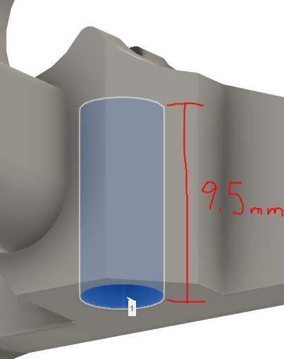
The bottom section (where the PTFE is inserted) should be cleaned out with a 4mm drill bit. For this, I use the drill bit without any drill (hand of powered) and just work it in some, and pull it out. The 4mm hole should only be cleaned out for 9.5mm. NOT the entire way.
In some areas of the world (like rural areas of the US,) metric drill bits might be harder to come by. I use a 5/64 inch bit instead of 2mm, and a 5/32 inch bit instead of 4mm. Converted to metric, they work out to 1.984mm and 3.967mm respectively.
.step file attached below...
Note (again) that this is sized for my effector on my printer. It's possible that this won't fit properly on another smart effector (if you are using something other than the E3D screw heatsink, for example.) The "effector adapter" in the step file is for 74mm arm spacing. That works for my printer, but might not for yours. Remember that your carriages must use the same arm spacing as your effector. The "PTFE Size Guide" is something I can stick on my effector with the heatsink in place (and without the extruder) - I shove a piece of PTFE into the heatsink as far as it'll go (to the heat break), pop on that size guide, and I know where to cut a length of PTFE to fit properly between the heatsink and extruder. (This is all described in an earlier post in this thread.)
Use this at your own risk. I'd suggest printing in ABS or PLA. (I had trouble with it printed in PETG.) See @mrac1's comments throughout this thread for suggested printer settings, stepper motor, motor current, etc.
The .step file included has 8.3mm diameter holes for the 8mm bearings (which works out well for me when printing ABS, but might not work out as well for others.) As well, the motor mount has holes that work perfectly (for me) for the following brass inserts: https://www.amazon.com/gp/product/B077CL322T. (That's a standard United States amazon link.) If you use different size inserts, the two larger holes on the bottom of the motor mount should be adjusted.
mrac1 extruder on smart effector.step
Finally, once again, a huge "thank you" should go to @mrac1 for the design I started from (and to Annex Engineering for the premise he started with.)
-
I'm currently dealing with the same issue regarding the filament path right after the BMG gears in my version (the path before the BMG gears is not as critical, I'll keep it as it is). I think that maybe using a PTFE tube correctly cut to follow the curve of the gear is not a bad idea too. I'll try this approach and gonna design a cutting jig to perfect cut the required PTFE part.
Also Titan Extruder got this kind of piece already designed, maybe it could fit, and it would cost nothing on aliexpress.
-
@Hergonoway said in Smart Effector including toolboard-capabilities?:
I'm currently dealing with the same issue regarding the filament path right after the BMG gears in my version (the path before the BMG gears is not as critical, I'll keep it as it is). I think that maybe using a PTFE tube correctly cut to follow the curve of the gear is not a bad idea too. I'll try this approach and gonna design a cutting jig to perfect cut the required PTFE part.
The problem with using a piece of PTFE extending up into the gear area is that on retraction, the PTFE might move up (toward the gears) slightly - and then get pulled up into the gearing.
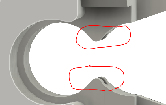
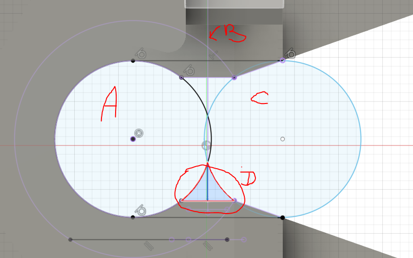
Designing the filament guide piece to have the bump area to guide filament was easier than I thought it would be in Fusion360. Start with the sketch facing the filament guide head-on, on a place centered on the filament path. Then draw a circle matching the smallest existing "hole" for the BMG gear. Then mirror that circle using the filament path as the mirror line. That leaves you the perfect area to extrude in both directions. Then fillet the new extrusions and re-do the filament hole path.
In the snippet below (of my actual sketch in 360), "A" is a 3 point circle based on 3 points projected from the inner-most gap for the BMG gear. "B" is a vertical line which is the filament path. "C" is a mirror of "A", using "B" as the mirror line. "D" is the area extruded to make the bump for the filament path. (Cleaning up the extrusions from D to meld properly with the rest of the body is annoying, but probably only because I don't know what I'm doing with Fusion360.) After that "bump" is made, I just used a 0.7mm fillet on the ridge, and then re-cut the filament path holes.
-
Here's my stab at a 74mm magball carriage for 40mm openbuild Vslot extrusions. Uses those fairly popular robotdigg metal belt tensioners to clamp the belts with the four holes in the center. I'll warn you that I'm not as good as some others in this thread with CAD
-
I am using a nimble 2 in a big delta heated chamber going up to 80-100c. Im going to print with big nozzles around .6 to 1.2. It claims this motor is high temp around 120c. Will this orbiter extruder motor do what i want or am i better off using the nimble 2 with my water cooled nema 18 off to the side. What i have works but better is always good. I guess i could maybe find a way to run water from the kryo then to the orbiter motor in my loop.
-
@garyd9
I tried to slice your version of mrac1's D3D with 0.8mm nozzle, I see a problem with the long hole for the stepper.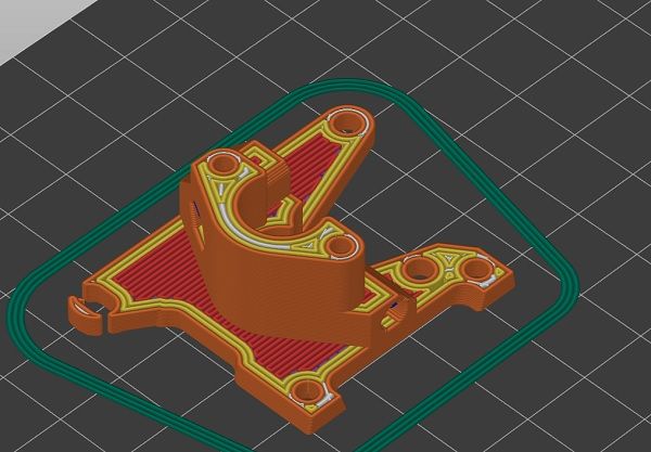
BTW: I found a cheaper/stronger motor for Orbiter and Sherpa mini. It's 2mm longer than the LDO. Will it still fit for the SmartEffector?
THX
Olaf -
@o_lampe said in Smart Effector including toolboard-capabilities?:
@garyd9
I tried to slice your version of mrac1's D3D with 0.8mm nozzle, I see a problem with the long hole for the stepper.You might need to enable a slicer option to extrude thin lines. I've only ever tested with a 0.4 nozzle and 0.4mm wide extrusions. If that doesn't work, load up the .step file and thicken that area.
BTW: I found a cheaper/stronger motor for Orbiter and Sherpa mini. It's 2mm longer than the LDO. Will it still fit for the SmartEffector?
That depends on your particular delta printer, what arm spacing you're using, the size of your build area in relation to the distance of the delta verticals to the build area, etc.
-
@o_lampe said in Smart Effector including toolboard-capabilities?:
BTW: I found a cheaper/stronger motor for Orbiter and Sherpa mini. It's 2mm longer than the LDO. Will it still fit for the SmartEffector?
there's a very recent alternative if you want more torque : http://ez3dpstore.com/PRE-ORDER-Sherpa-Mini--NEMA14--8t-Pinion-Motor_p_69.html
8t instead of 10t, still in pre-order state tho, but worth the wait imo
-
@hergonoway
Changing the gear ratio is just a trick IMHO, you win more torque but loose retraction speed.
They don't say much about the motor as such. Their 1004 motor has significantly different windings than the 36HS2418. It's trimmed for torque (high inductivity) but overheats fast, because of the high coil-resistance.
The motor I picked is meant for the Hitchhiker, where speed is more important than grunt. -
@o_lampe yeah heat concerns me a bit, but I generally print mechanical parts in ASA or PCmax, so it "should" be ok, I still have to print my version of the D3D tho to see it for myself. Regarding retraction speed, it implies going from 50:10 to 50:8 so there's no impact since we're dealing in the <1mm field. I could be slightly concerned for jerk but I need to test it beforehand.
That's remind me that V1 of HextrudORT should be available