Dual extruder coordinates with illustration
-
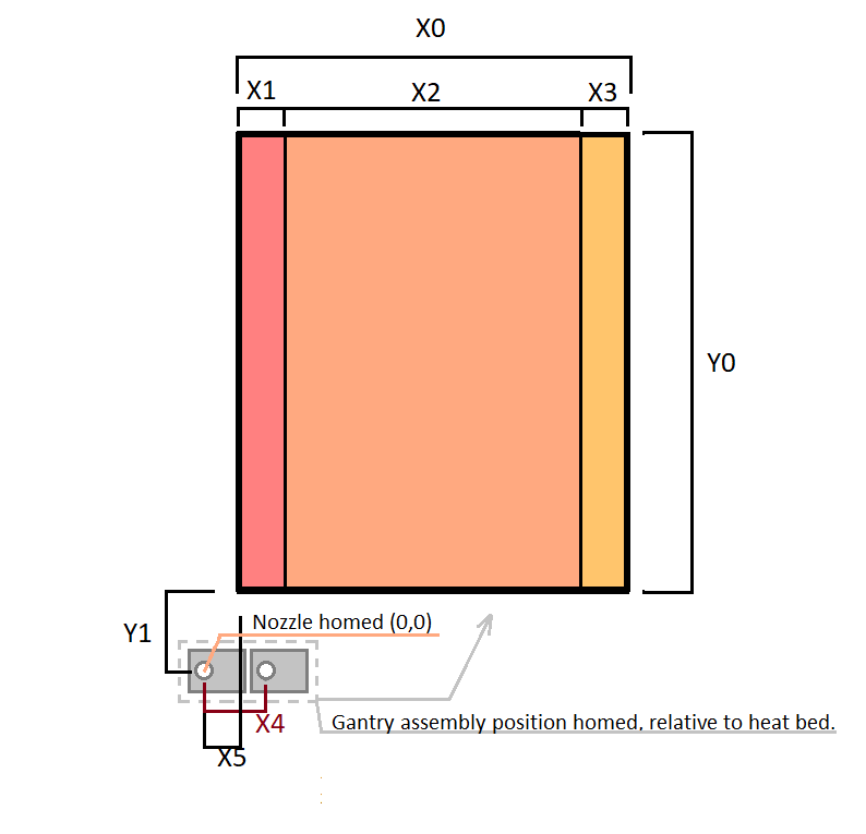
Hello folks, I am in the middle of setting up my duet for the first time with more motors etc, and I have some questions regarding dual extrusion coordinates and gcode using RRF3. First, if these questions are already covered somewhere share the link! I'd be happy to read. Check out my fancy illustration for references. Not to scale - exaggerated to show detail. The two extruders land outside of the heat bed when X and Y end stops are triggered.
- Is the point where both end stops triggered (0,0) regardless of where the print area is? Or is (0,0) usually the start of the print area?
- I know this is a big question, but where do I input these offsets in order to get the nozzle to land on the heat bed, in the gcode?
- When I tell the printer to home, should the nozzles find the end stops and then move to the print area, or should they move to the print area once a print actually starts?
- Is it possible to define different print areas for the two hot ends in order to make use of the space on the sides when printing with just 1? (left hot end can print in X1 + X2, and right hot end can print in X2 + X3)
- Is a print area defined with starting points and lengths or is it defined with coordinates?
I know this is a lot to answer but thanks to anyone who helps!
X0 - 200mm
Y0 - 220mm
X1, X3, X4 - 27mm (I assume all 3 should be the same dimension)
X2 - 146mm
Y1 - 30mm
X5 - 15mmThanks, Dad
-
@printerdad
I'm roughly at the same stage of rebuild, so I read a lot about IDEX printer setup lately. But on the practical side I'm a dual-extrusion noob.-
- the homing position is_what_it_is. You home outside of the printarea, so your homing coords should have at least one position bigger or smaller than the printable area.
I assume you want to have (0,0) at the corner of the printable area and you want your slicer to have the same coords)
- the homing position is_what_it_is. You home outside of the printarea, so your homing coords should have at least one position bigger or smaller than the printable area.
-
- The way to tell FW the homing coords is using M208
Tool 0 is 'X' Tool 1 is 'U'. You have to sort out the tool offsets and reflect that in M208. Two different printareas for X- and U-tool, but both relative to (0,0). The endstop config is also different: you home the left tool to min-endstop and the right tool to max-endstop
- The way to tell FW the homing coords is using M208
-
- This is a question for experienced IDEX users, but I'd leave the tools at homing position. ( and also park them there during prints)
-
- is answered in 2) and you have to setup your slicer the same way (tool offsets at least)
-
- see M208 : it's all coords
-
-
@o_lampe
Thanks for the info. I didnt even know IDEX was a thing, good article. -
I had a couple of Chimera dual extruder setups with a duet a few years back. I got away from them but I will try and help. I am under the impression that this is not an IDEX printer. Just a standard dual extruder setup.
-
Not necessarily. You can set up the home locations to be negative numbers. This way you can get to the home location and still be able to set your printing area to start at 0,0 to match your slicer.
-
By setting up M208 appropriately. I would use the following code using the numbers you provided above. Lets call the left handle nozzle T0 for this instance.
M208 X-42.0 Y-30.0 Z0 S1 ; set axis minima
M208 X146.0 Y220.0 Zxxx.x S0 ; set axis maximaThen in your homing files you need to make sure the homing "G1" moves have an H1 attached.
This really cuts down on your usable space but is generally the "easiest" way to handle these scenarios.
Tool offsets would look like this:
G10 P0 X0 Y0 Z0 ; set tool 0 axis offsets
G10 P1 X27.0 Y0 Z0 ; set tool 1 axis offsets
(I may have the sign backwards for the X axis offset for T1. )-
Yes the nozzles should find home first, after that it is up to you. I typically move my heads to a position that they can be seen easily while they are heated. This this case that could be your home position. The rest is really up to you and how you want your slicer/firmware to be set up. IE it doesn't really matter.
-
This is what @o_lampe was referring to. As I understand it you only have 1 X axis and no U axis. I think you could set up "virtual" U axis for T1 with its own set of limits, and maybe another axis for T0 with another set up limits. In reality this is difficult to do for space that may not make a lot of sense to use. Others will have to chime in for how they have handled these situations before.
You could also handle this using work coordinate systems.
- See my response for #2. That's the general setup. Plus you need to define your print area in your slicer. This would basically be lengths of the "maxima" line above.
This answers some of your questions I hope.
Edit: messed up P1 for tool 1
-
-
@alex-cr
yes very helpful, thank you -
@printerdad just to confuse things slightly, I don't actually use the tool offsets for the chimera in the config for my machine. As far as the machine is concerned, both nozzles are at the same point, nominally the position of the left nozzle. Instead, I include the offsets in my slicer (PrusaSlicer).
I found that during a tool change, if I didn't use the offsets in the slicer, it tended to leave one of the nozzles over the print, so I got drooling and defects. Might be that I missed something in my slicer setup though... -
It may make more sense to have 0,0 be at the center of the bed and then work out from there.
https://duet3d.dozuki.com/Wiki/Centering_the_bed_or_setting_the_bed_origin
-
@phaedrux said in Dual extruder coordinates with illustration:
It may make more sense to have 0,0 be at the center of the bed and then work out from there.
https://duet3d.dozuki.com/Wiki/Centering_the_bed_or_setting_the_bed_origin
I wondered if that was a thing. I wasnt sure if negative coords were appropriate. Ill check out the link, thank you.
-
@printerdad said in Dual extruder coordinates with illustration:
I wasnt sure if negative coords were appropriate.
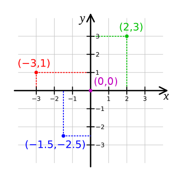
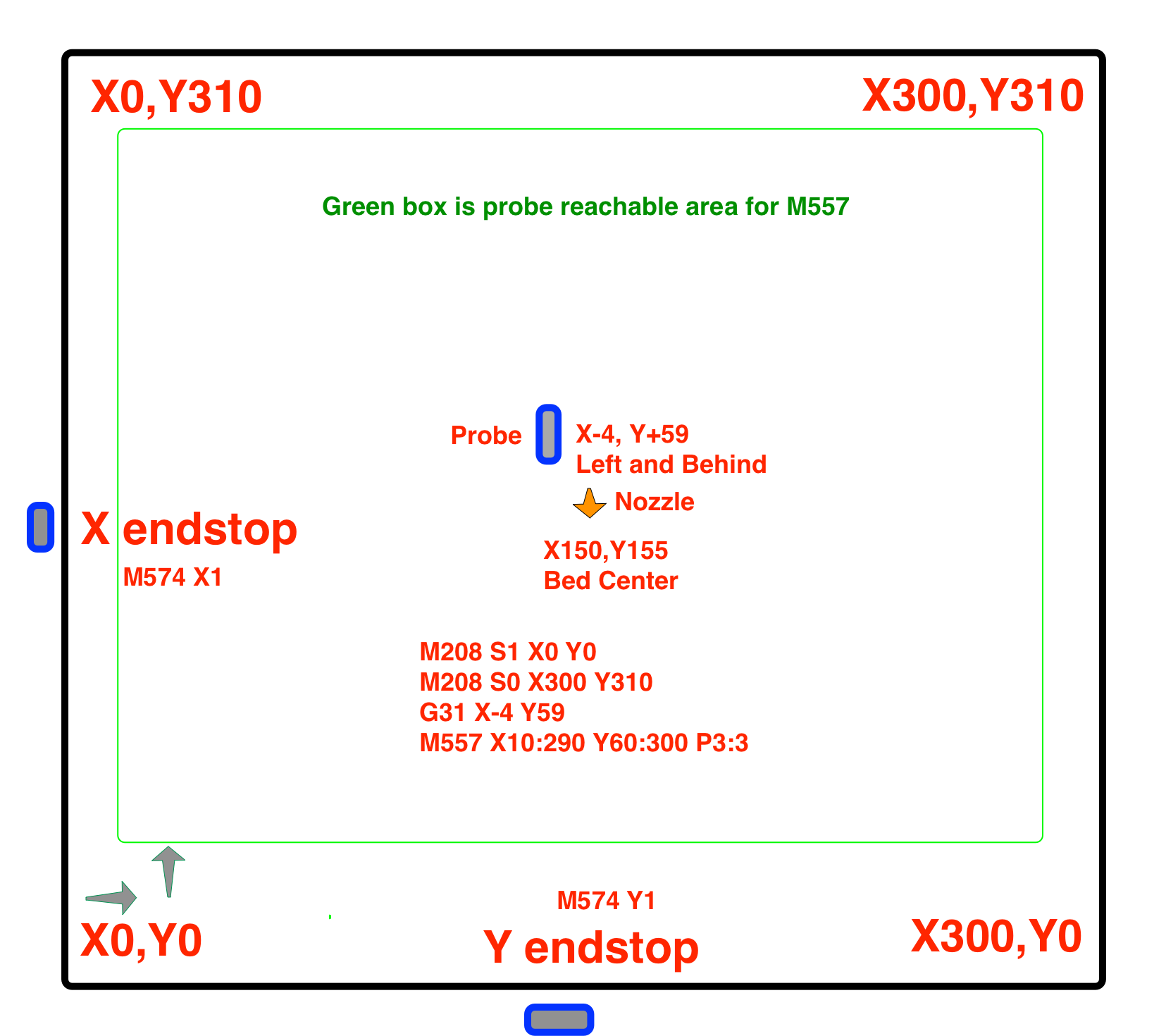
They certainly are. The important thing is that -x moves to the left, +x moves to the right, +y moves back and -y moves forward. Where the 0,0 point is doesn't matter so much. Either the front left corner of the bed, or the center of the bed is a good choice. If you use the center make sure to tell the slicer it's at the center and define the bed size and it will respect the bed limits. The firmware will handle the endstop positions you define with M208.
Doing up a diagram like this may help to visualize.
-
thank you im going to use this too
-
Setting bed centre to be X0 Y0 has various advantages; but for IDEX printers it also makes it easier to configure a tool for mirror printing.