Duex I2C Hardware Configuration
-
TL:DR; If I had a correctly exported BOM that matched the kicad model I am looking at, I could answer most if not all of my questions. I'm looking at Duex5 0.9a as Duex5 1.0 has no kicad model in the Open Source documentation I downloaded.
Totally understand if this is beyond the scope of support you offer, but can you help me understand how the I2C gets connected on the duex? In the meantime I am working on answering my own questions, but I thought it might be worth making a post about.
I gathered most of it already but there are some gaps in my understanding, when I treid to export the BOM from Kicad it gave me a garbled mess and the pictures online do not show lettering very well on some SMC components. A correctly exported BOM would answer most of my questions.
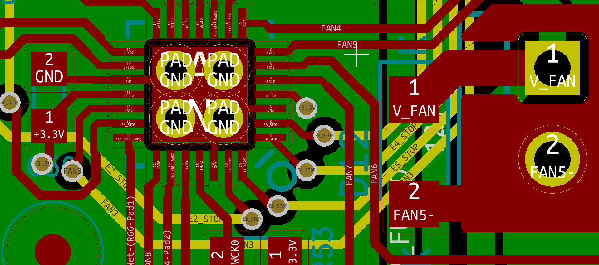
I2C used: SX1509B
?Pins 1, 2, 20, 27, 28 Gets connected to their endstop signal, has a 1k resistor, then a LED? connecting it to ES_V which has a voltage selection header
Pin 3 Gets GND
Pin 4 Gets 3.3v
Pin 5, 6, 7, 8, 19, 22 has a 10k resistor connecting it to Fan# mosfet Pin S and GND. Also it has a 1k resistor connecting it to Fan7 mosfet G. The Mosfet is then connected to FAN#-. FAN#- is connected to a DO-219AB that is connected to V_FAN. V_Fan goes to a voltage selection header.
Pin 9 connects to EXP pin 24 and get a 1k resistor to 3.3v
Pin 10 gets connected to GND with an OR and has an unpopulated surface mount to 3.3v labeled OR DNP
Pin 11 OSCIO is a test pin
Pin 12 Gets 3.3v
Pin 13, 14, 15, 16 get a 10k resistor to 5V and go to GPIO4, 3, 2, 1
Pin 17 Gets connected to GND
?Pin 18 gets connected to 3.3v and has a 0u1 capacitor connecting it to ground
Pin 21 gets a 1k resistor connecting it to GND
Pin 23 Gets a 10k resistor to 3.3v
Pin 24 I2C Data connects to EXP 45 and has a 1k resistor to 3.3v
Pin 25 I2C Clock connects to EXP 46 and has a 1k resistor to 3.3v
Pin 26 is GND
-
@sphyloid Just use a different spreadsheet program, I am sure kiCAD is not broken.
-Signed future you
-
@sphyloid open the schematic in KiCAD, it will show you the components and in the properties is often more information (not sure if I added part numbers to the Duex schematics tho).
-
@t3p3tony That almost cleared everything up. Just 3 last minor details.
-
What is the capacitor capacity
?Pin 18 gets connected to 3.3v and has a 0u1 capacitor connecting it to ground -
What LED is used on the endstops, I assume its not too critical
-
Is Pin 4 of the EXP remapped from e2.stop to something related to Stallguard? It is labeled E2_TST gets put into a 74HC32 under the Stallguard OR schematic and then sent over to one of the step drivers. If it is, can I simply omit this? The external drivers I am using are self managing so I assume yes.
-
-
@sphyloid, 0u1 typically means 0.1uf = 100nf.