Navigation

    Duet3D Logo

    Duet3D

    • Register
    • Login
    • Search
    • Categories
    • Tags
    • Documentation
    • Order
    1. Home
    2. Sphyloid
    • Profile
    • Following 0
    • Followers 0
    • Topics 13
    • Posts 37
    • Best 8
    • Groups 0

    Sphyloid

    @Sphyloid

    9
    Reputation
    8
    Profile views
    37
    Posts
    0
    Followers
    0
    Following
    Joined Last Online

    Sphyloid Follow

    Best posts made by Sphyloid

    • Anyone notice the Duet website is written on the back in solder?

      Seriously doubt many people noticed this, but I find it beyond cool. The duet website is written the the back copper and in the back solder mask so when it is wave soldered the website gets written in solder! Totally showing off, but its super cool.

      Back Copper:

      backCopper.PNG

      Back Solder Mask:

      backMask.PNG

      IRL:

      solderWebsite.jpg

      posted in General Discussion
      Sphyloid
      Sphyloid
    • RE: X Axis jumps randomly during printing

      @Phaedrux The Duet still turns on and runs fine until it skips X around. I found where the short was and all it had access to short was the X endstop and X stepper.

      Ended up ordering a replacement, had to go with a cloned version since I could not find a real duet anywhere. The printer works fine now. Though I found there was no cooling for the duet, the rear of the board had little to no clearance and the board cooling fan was choked with the air flowing away from the board instead of under.

      I added hotglue to the main ribbon solder joints and the rear of the connectors and removed the grounding wire that may have shorted them. Also I wired the X stepper directly to the board so that the breakout only has the 5V endstop.

      Thank you for the help guys, looking forward to having my duet running on another of my machines.

      X_Board_A_1024x1024.jpg

      posted in Duet Hardware and wiring
      Sphyloid
      Sphyloid
    • IDEX H-Bot

      Yes, this is a terrible idea for many reasons. I simply want to know if this is possible to configure with the stock rep-rap firmware.

      As the title suggests, the independent dual extruder machine would have two layers of the H-Bot motion system. Each extruder would have it's own X and Y motor, but the firmware would need to keep both extruders at the same Y value.

      Thank you,
      Will

      posted in Firmware installation
      Sphyloid
      Sphyloid
    • RE: Duet 2 Wifi Expansion board IO usage

      @phaedrux Perhaps this is worth promoting to its own thread. Ill make one real quick.

      posted in Duet Hardware and wiring
      Sphyloid
      Sphyloid
    • RE: IDEX H-Bot

      @bot The reason I say it is terrible is complicated. While functional and useful, I am unsure of the marketability of the product. Other similar designs offer different advantages that may be preferable to most other people.

      Honestly it is quite alarming how little I know about getting this to work at a firmware level. Any tips on where I could get better guidance?

      If you are interested I wrote a little about it in response to a strictly theoretical build. While I have not received all the pieces to my machine from the machine shops, I regard my design as functional given that myself and two senior level engineers, one with a doctorates in mechanical engineering, have reviewed the design. Furthermore I have done extensive FEA on the assembly with a safety factor of 5 for a total deflection of 0.2mm on the Z, and 0.02mm on the X/Y axis. The critiques on my final design were in fine alignment and assembly, not mechanical functionality. It has been completely re-engineered 5 times.

      "I have engineered an H-bot motion system. The reason my design works and this design will not is due to FEA. If you ran FEA on this design it would not be stiff at all.

      Not to mention you would never actually be able to assemble this due to all of the excess rails. Getting them all aligned would be a nightmare. Not to mention you have all your pulleys and motors cantilevered outside the frame. You have all of the extrusions running the thin way where all of the twisting moment is applied to the y carriages.

      Look at how the makerbot replicator H bot is designed. These are engineers from stratasys if I am not mistaken.

      My H-Bot design is infinitely more stiff and requires no more space than a coreXY because of the type of pre-loaded linear rails I used and in what orientation I used them. Christ, I have them bolted to a half inch of blanchard ground steel almost a foot wide stretching the length of the machine reinforced by two 50x100mm aluminum extrusions and the rest of the machine is built with 40x120mm. Bear in mind, this is a large machine.

      Having an IDEX H-bot is a mistake from a complexity standpoint, this did not stop me from trying. I mounted the pullies with roller bearings on 12mm steel rod with polymer bushings in between. Yes you can get it to work, but to what end? Two printers for the price of 1 but at 4x the cost of a simpler design? There would need to be strong motivation, like high precision and speed milling operations to warrant such a design.

      CoreXY is not as accurate as H-bot simply because when you have the rigidity required for high accuracy, H-bot is simpler to design. Unfortunately, for using H-bot in 3d printing specifically, 3D printers are not required to be high accuracy. It is a very messy process, there is no benefit from having high precision.

      As for speed, H-bot wins again. When you have enough stiffness, you can use huge motors. To re-iterate, H-bot is easier to engineer when you have enough stiffness. You need to take advantage of that stiffness if you do not want to lose speed.

      Speaking of cost the original makerbot cartesean system is far superior to all the other 3d printing specific designs. You can make 10 adequate sheet metal cartesean machines for the price of one high-precision H-bot machine not including the labor intensive process of FEA engineering the H-bot. It took me a full year to design a great H-bot when I could have designed an adequate sheet metal machine of the same size in a few months. Granted it would need to have the Z axis bolted to a cement wall, or have multiple lead-screws ( eww ).

      The motivation for my exercise in futility, encase you had not guessed, was space and time. I have space and electricity for one painfully large 500kg, 35A of 220V machine, not two. Furthermore, I want highly dimensionally accurate parts fast in PEEK, PEI, and PC. I cannot waste time and money playing with taking a part off the printer onto a $30,000 CNC I dont have. Ontop of that, I want to be able to have the option of having two half sized machines when I do not need the full build envelope. Hell, maybe other people feel the same way. Maybe they will pay top dollar for my work."
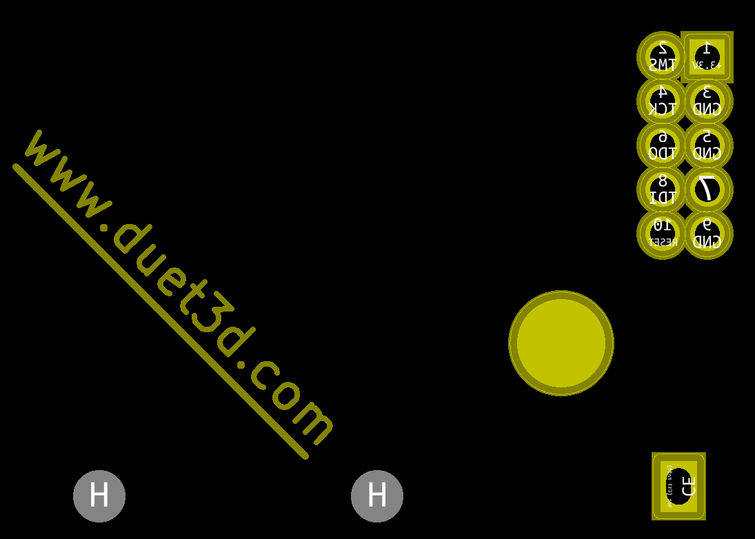
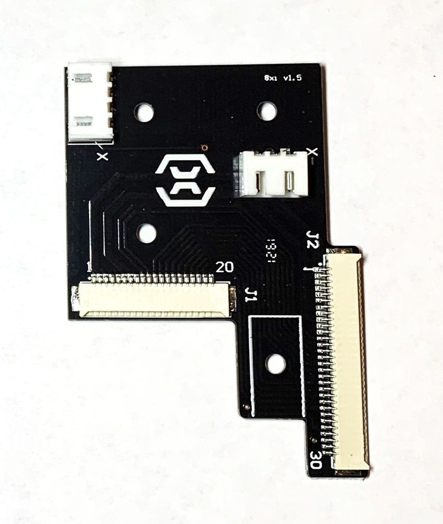
      posted in Firmware installation
      Sphyloid
      Sphyloid
    • Duex0 Still on the way?

      Im putting a significant amount of effort into making my own version of this. Admittedly the drives will have no SPI option as that is irrelevant to my specific machine, adds significant complexity, and the project has low marketability.

      If there is something in the works, I would obviously want to use that instead of spending time engineering something that will likely be inferior, even if it has a nice BLTouch port.

      posted in Duet Hardware and wiring
      Sphyloid
      Sphyloid
    • RE: IDEX H-Bot

      @dc42 Thank you so much! My next question, has anyone actually used this configuration? If so, how difficult was it to configure?

      I did not get much after looking up "CoreXYUV kinematics" any links you know off hand?

      posted in Firmware installation
      Sphyloid
      Sphyloid
    • RE: E3.STOP Endstop not working as expected

      Edit: I read up on pullup resistors and I understand now. Thanks!

      posted in Firmware installation
      Sphyloid
      Sphyloid

    Latest posts made by Sphyloid

    • Duex I2C Pin 10 OR Resistor

      Cannot seem to figure out what this OR resistor is. From what I can see on the sparkfun breakout board schematic and the documentation on the SX1509B it feels like this should be a solder bridge. Obviously this is not a solder bridge.

      ORResistor.png

      duexP10.PNG

      sparkfunP10.PNG

      posted in Duet Hardware and wiring
      Sphyloid
      Sphyloid
    • RE: What Rectifier is used for Fans on DUEX

      @sphyloid Look in the duet 2 wifi schematic, it has the info in the properties. http://uk.farnell.com/taiwan-semiconductor/es1cl/diode-ultra-fast-s1a-150v/dp/1559125

      posted in Duet Hardware and wiring
      Sphyloid
      Sphyloid
    • What Rectifier is used for Fans on DUEX

      ES1CL R3G

      http://uk.farnell.com/taiwan-semiconductor/es1cl/diode-ultra-fast-s1a-150v/dp/1559125

      fanMos.PNG

      posted in Duet Hardware and wiring
      Sphyloid
      Sphyloid
    • RE: Duex I2C Hardware Configuration

      @t3p3tony That almost cleared everything up. Just 3 last minor details.

      • What is the capacitor capacity
        ?Pin 18 gets connected to 3.3v and has a 0u1 capacitor connecting it to ground

      • What LED is used on the endstops, I assume its not too critical

      • Is Pin 4 of the EXP remapped from e2.stop to something related to Stallguard? It is labeled E2_TST gets put into a 74HC32 under the Stallguard OR schematic and then sent over to one of the step drivers. If it is, can I simply omit this? The external drivers I am using are self managing so I assume yes.

      posted in Duet Hardware and wiring
      Sphyloid
      Sphyloid
    • RE: Duex I2C Hardware Configuration

      @sphyloid Just use a different spreadsheet program, I am sure kiCAD is not broken.

      -Signed future you

      posted in Duet Hardware and wiring
      Sphyloid
      Sphyloid
    • RE: What I2C Expander is used On the Duex?

      @t3p3tony said in What I2C Expander is used On the Duex?:

      SX1509B

      It was my spreadsheet viewer. For some reason it could not understand the formatting. Might have to buy excel, opening it with notepad shows that everything is there and correct

      posted in Duet Hardware and wiring
      Sphyloid
      Sphyloid
    • Duex I2C Hardware Configuration

      TL:DR; If I had a correctly exported BOM that matched the kicad model I am looking at, I could answer most if not all of my questions. I'm looking at Duex5 0.9a as Duex5 1.0 has no kicad model in the Open Source documentation I downloaded.

      Totally understand if this is beyond the scope of support you offer, but can you help me understand how the I2C gets connected on the duex? In the meantime I am working on answering my own questions, but I thought it might be worth making a post about.

      I gathered most of it already but there are some gaps in my understanding, when I treid to export the BOM from Kicad it gave me a garbled mess and the pictures online do not show lettering very well on some SMC components. A correctly exported BOM would answer most of my questions.

      I2C used: SX1509B

      ?Pins 1, 2, 20, 27, 28 Gets connected to their endstop signal, has a 1k resistor, then a LED? connecting it to ES_V which has a voltage selection header

      Pin 3 Gets GND

      Pin 4 Gets 3.3v

      Pin 5, 6, 7, 8, 19, 22 has a 10k resistor connecting it to Fan# mosfet Pin S and GND. Also it has a 1k resistor connecting it to Fan7 mosfet G. The Mosfet is then connected to FAN#-. FAN#- is connected to a DO-219AB that is connected to V_FAN. V_Fan goes to a voltage selection header.

      Pin 9 connects to EXP pin 24 and get a 1k resistor to 3.3v

      Pin 10 gets connected to GND with an OR and has an unpopulated surface mount to 3.3v labeled OR DNP

      Pin 11 OSCIO is a test pin

      Pin 12 Gets 3.3v

      Pin 13, 14, 15, 16 get a 10k resistor to 5V and go to GPIO4, 3, 2, 1

      Pin 17 Gets connected to GND

      ?Pin 18 gets connected to 3.3v and has a 0u1 capacitor connecting it to ground

      Pin 21 gets a 1k resistor connecting it to GND

      Pin 23 Gets a 10k resistor to 3.3v

      Pin 24 I2C Data connects to EXP 45 and has a 1k resistor to 3.3v

      Pin 25 I2C Clock connects to EXP 46 and has a 1k resistor to 3.3v

      Pin 26 is GND

      FanController.PNG

      posted in Duet Hardware and wiring
      Sphyloid
      Sphyloid
    • RE: What I2C Expander is used On the Duex?

      @t3p3tony Thank you so much!

      posted in Duet Hardware and wiring
      Sphyloid
      Sphyloid
    • What I2C Expander is used On the Duex?

      Judging from the previous discussion I had with @dc42 about adding fans and heaters to the expansion board I am developing, he implied that the exact I2C expander used would not force a firmware change. However since I do not want to mess with any firmware, I want to use the same exact parts and in the same config as used on the Duex where possible. My needs require it to be different in some areas. Thus, I am drawing heavily from opensource kicad model of the Duex 0.9a which is the latest duex open source documentation has been released on.

      Unfortunately when I exported the BOM on the Duex, 5 kicad puked the below out, and I cannot find any pictures of the Duex detailed enough to read the chip:

      䤢≤∻敄楳湧瑡牯㬢倢捡慫敧㬢儢慵瑮瑩≹∻敄楳湧瑡潩≮∻畓灰楬牥愠摮爠晥㬢਍㬱唢∸∻塓㔱㤰≂ㄻ∻塓㔱㤰≂㬻഻㈊∻㙃∱∻彃㘰㌰㬢㬱〢ふ‱㔳≖㬻഻㌊∻ㅍⰱㅍ䴬ⰲ㍍䴬ⰹㅍ∰∻楆畤楣污ㅟ浭䑟慩㉟㔮洴彭畏整彲潃灰牥潔≰㘻∻䥆≄㬻഻㐊∻㙕唬ⰵㅕ唬ⰲ㍕㬢吢䍍㘲〶㬢㬵吢䍍㘲〶㬢㬻਍㬵䨢∹∻䥐彎剁䅒彙破∱ㄻ∻㑅䴠呏㬢㬻਍㬶䨢㐲㬢倢义䅟剒奁㉟ㅘ㬢㬱䔢‴䕔偍㬢㬻਍㬷䨢㔲㬢倢义䅟剒奁㉟ㅘ㬢㬱䘢乁䰯䑅㔠㬢㬻਍㬸䨢㤲㬢倢义䅟剒奁㉟ㅘ㬢㬱䔢‶䕔偍㬢㬻਍㬹䨢ㄳ㬢倢义䅟剒奁㉟ㅘ㬢㬱䘢乁䰯䑅㜠㬢㬻਍〱∻剔ⰷ剔ⰹ剔ⰶ剔ⰸ剔〱听ㅒ∱∻体ⵔ㌲㬢㬶倢噍〴乕∲㬻഻ㄊ㬱唢〱唬∹∻協体ⵐ㐱㬢㬲㜢䠴呃㈰㬢㬻਍㈱∻㥃䌬㤲䌬ⰳ㙃䌬㈳㬢䌢た〶∳㔻∻田‱㔠嘰㬢㬻਍㌱∻ㅃⰱ㍃ⰴ㕃ⰰ㕃ⰱ㕃ⰲㅃⰰㅃⰲ㍃ⰳ㙃ⰴ㕃∳∻彃㘰㌰㬢〱∻田∱㬻഻ㄊ㬴䌢㌱䌬㐱䌬㔱䌬㔳䌬㘳㬢䌢た〶∳㔻∻田㜴㬢㬻਍㔱∻ㅃⰸㅃⰹ㉃ⰰ㉃ⰱ㍃ⰹ㑃ⰰ㑃ⰱ㑃ⰲ㉃ⰲ㉃∳∻彃㘰㌰㬢〱∻田㄰堠刷ㄠ┰㔠嘰㬢㬻਍㘱∻㉃ⰷ㍃ⰰㅃ䌬ⰴ㝃㬢䌢た〶∳㔻∻由㔠嘰㬢㬻਍㜱∻㍄㬢䐢た〶∳ㄻ∻㑅瑳≰㬻഻ㄊ㬸䐢∴∻彄㘰㌰㬢㬱䔢猵灴㬢㬻਍㤱∻㥄㬢䐢た〶∳ㄻ∻㑅䠠慥≴㬻഻㈊㬰䐢〱㬢䐢た〶∳ㄻ∻㕅䠠慥≴㬻഻㈊㬱䐢ㄱ㬢䐢た〶∳ㄻ∻㉅䠠慥≴㬻഻㈊㬲刢ⰱ㉒刬㔱刬ㄲ刬㠴刬㤴刬〵刬ㄵ刬㈵刬㌵刬㘶刬㐱刬㜴刬ⰳ㝒∲∻归㘰㌰㬢㔱∻䬱㬢㬻਍㌲∻㙒刬ⰷㅒⰱㅒⰲㅒⰳ㉒ⰳ㉒ⰴ㉒ⰷ㉒ⰸ㍒ⰱ㕒㬢刢た〶∳ㄻ㬱㈢刲㬢㬻਍㐲∻㍒ⰶ㍒ⰲ㍒ⰳ㍒ⰴ㍒∵∻归㘰㌰㬢㬵㐢㝋㬢㬻਍㔲∻㍒ⰷ㍒ⰸ㍒ⰹ㑒ⰰ㑒∱∻归㘰㌰㬢㬵ㄢ〸≒㬻഻㈊㬶刢㈴刬㌴刬㐵刬㔵刬㘵刬㜵刬㠵刬㤵刬㐴刬㔴刬㜶㬢刢た〶∳ㄻ㬱ㄢ䬰㬢㬻਍㜲∻㙒ⰱ㙒ⰲ㙒ⰳ㙒ⰴ㙒∵∻归㘰㌰㬢㬵㐢㝋〠ㄮ∥㬻഻㈊㬸䌢ⰲ㕃䌬ⰸ㉃ⰸ㍃ⰱ㕃ⰶㅃ∶∻彃䱅䍅㙟㌮㝸㜮㬢㬷ㄢ〰⁵㔳≖㬻഻㈊㬹䐢∱∻彄㘰㌰㬢㬱䔢猲灴㬢㬻਍〳∻㉄㬢䐢た〶∳ㄻ∻㍅瑳≰㬻഻㌊㬱䐢∵∻彄㘰㌰㬢㬱䔢猶灴㬢㬻਍㈳∻㡄㬢䐢た〶∳ㄻ∻㍅䠠慥≴㬻഻㌊㬳䐢㌱㬢䐢た〶∳ㄻ∻㙅䠠慥≴㬻഻㌊㬴䨢∲∻䕔䵒㉟圭奁㙟㌮洵≭ㄻ∻䥖≎㬻഻㌊㬵䨢∳∻䥐彎剁䅒彙破∱ㄻ∻㉅䴠呏㬢㬻਍㘳∻㕊㬢倢义䅟剒奁㑟ㅸ㬢㬱䔢″位≔㬻഻㌊㬷䨢㈱㬢倢义䅟剒奁㑟ㅸ㬢㬱䔢‵位≔㬻഻㌊㬸䨢㐱㬢倢义䅟剒奁㑟ㅸ㬢㬱䔢‶位≔㬻഻㌊㬹䨢㘱㬢倢义䅟剒奁㉟堵∲ㄻ∻义啐≔㬻഻㐊㬰䨢㤱㬢倢义䅟剒奁㉟ㅘ㬢㬱䔢′䕔偍㬢㬻਍ㄴ∻㉊∰∻䥐彎剁䅒彙堲∱ㄻ∻䅆⽎䕌⁄∳㬻഻㐊㬲䨢ㄲ㬢倢义䅟剒奁㉟ㅘ㬢㬱䔢″䕔偍㬢㬻਍㌴∻㉊∳∻䥐彎剁䅒彙堲∱ㄻ∻䅆⽎䕌⁄∴㬻഻㐊㬴䨢㜲㬢倢义䅟剒奁㉟ㅘ㬢㬱䔢‵䕔偍㬢㬻਍㔴∻㉊∸∻䥐彎剁䅒彙堲∱ㄻ∻䅆⽎䕌⁄∶㬻഻㐊㬶䨢㌳㬢䴢塁呟䵅彐䉄㬢㬱匢䥐∰㬻഻㐊㬷刢ⰸ㥒刬〱刬㘱刬㜱刬㠱刬㔲刬㘲刬㤲刬〳㬢刢ㅟ〲∶ㄻ㬰〢げㄵ㬢㬻਍㠴∻㙊㬢倢义䅟剒奁㉟ㅘ㬢㬱㔢彖啁彘义㬢㬻਍㤴∻ㅊ㬢䌢乏彎砳∱ㄻ∻㉅灴㬢㬻਍〵∻㑊㬢䌢乏彎砳∱ㄻ∻㍅灴㬢㬻਍ㄵ∻㝊㬢䌢乏彎砳∱ㄻ∻㑅灴㬢㬻਍㈵∻㡊㬢䌢乏彎砳∱ㄻ∻㕅灴㬢㬻਍㌵∻ㅊ∰∻佃乎㍟ㅸ㬢㬱䔢琶≰㬻഻㔊㬴䨢ㅐ㬢䌢乏彎砳∱ㄻ∻嘵䄠塕匠汥捥≴㬻഻㔊㬵䨢㌱㬢倢湩䡟慥敤彲瑓慲杩瑨ㅟㅸ∰ㄻ∻佃乎た報〱㬢㬻਍㘵∻㕃∴∻彃㘰㌰㬢㬱㈢渲≆㬻഻㔊㬷䌢㔵䌬㠵㬢䌢ㅟ〲∶㈻∻〱⁵㔳≖㬻഻㔊㬸䌢㤵䌬〶䌬㌶㬢䌢た〸∵㌻∻〱⁵㔳≖㬻഻㔊㬹䨢〴㬢倢湩䡟慥敤彲瑓慲杩瑨㉟へ∳ㄻ∻佃乎た堲㌰㬢㬻਍〶∻偊∲∻啊偍剅㬢㬱ㄢ嘲䕟≎㬻഻㘊㬱䰢∱∻彃㈱〱㬢㬱ㄢ䡵㬢㬻਍㈶∻㉌㬢䰢㙟㙸㬢㬱ㄢ田≈㬻഻㘊㬳刢㘴㬢刢た〶∳ㄻ∻〲䬰㬢㬻਍㐶∻㙒∸∻归㘰㌰㬢㬱ㄢ⸰䬵ㄠ∥㬻഻㘊㬵刢ㄷ㬢刢た〶∳ㄻ∻㔷到ㄠ∥㬻഻㘊㬶唢ㄱ㬢儢乆㘱㐭㑸㬢㬱䄢㐴㌰㬢㬻਍㜶∻剔ⰵ剔ⰴ剔ⰳ剔ⰲ剔∱∻ⵄ䅐≋㔻∻偉い㘳ぎ䰴㬢㬻਍㠶∻偊∳∻佃乎㍟ㅸ㬢㬱䔢摮瑳灯嘠汯慴敧匠汥捥≴㬻഻㘊㬹唢㈱㬢吢卓偏ㄭ∴ㄻ∻㐷䍈㈳㬢㬻਍〷∻㍊∹∻䥐彎剁䅒彙堳∱ㄻ∻㙅卟佔≐㬻഻㜊㬱䨢㠳㬢倢义䅟剒奁㍟ㅘ㬢㬱䔢張呓偏㬢㬻਍㈷∻㍊∷∻䥐彎剁䅒彙堳∱ㄻ∻㑅卟佔≐㬻഻㜊㬳䨢㘳㬢倢义䅟剒奁㍟ㅘ㬢㬱䔢弳呓偏㬢㬻਍㐷∻㍊∰∻䥐彎剁䅒彙堳∱ㄻ∻坐彍∳㬻഻㜊㬵䨢㘲㬢倢义䅟剒奁㍟ㅘ㬢㬱倢䵗㉟㬢㬻਍㘷∻㉊∲∻䥐彎剁䅒彙堳∱ㄻ∻坐彍∱㬻഻㜊㬷䨢㔳㬢倢义䅟剒奁㍟ㅘ㬢㬱䔢弲呓偏㬢㬻਍㠷∻㍊∲∻䥐彎剁䅒彙堳∱ㄻ∻坐彍∴㬻഻㜊㬹䨢㐳㬢倢义䅟剒奁㍟ㅘ㬢㬱倢䵗㕟㬢㬻਍〸∻㑒刬㤱刬〲刬㌷㬢刢た〶∳㐻∻到㬢㬻਍ㄸ∻ㅊ∱∻敔浲湩污求捯彫桐潥楮彸呐㌭㔮浭ㅟ瀰汯㬢㬱䌢乏彎㄰ㅘ∰㬻഻㠊㬲刢㈲㬢刢た〶∳ㄻ∻䬳∳㬻഻㠊㬳䨢㔱㬢倢义䅟剒奁㉟ㅘ㬢㬱䘢乁䰯䑅㠠㬢㬻਍㐸∻ㅄⰲㅄⰴㅄⰵㅄⰶㅄⰷㅄ∸∻佄㈭㤱䉁㬢㬶䐢ⵏㄲ䄹≂㬻഻㠊㬵䴢ⰵ㝍䴬ⰴ㙍㬢䘢硩湩彧㑍㬢㬴䴢問呎义≇㬻഻㠊㬶刢〶㬢刢た〶∳ㄻ∻到䐠偎㬢㬻਍㜸∻ㅊ∷∻䥐彎剁䅒彙堲∱ㄻ∻㈱≖㬻഻㠊㬸䌢㜱㬢䌢た〶∳ㄻ∻田‱㔳≖㬻഻㠊㬹䌢㈶㬢䌢䕟䕌彃⸶砳⸷∷ㄻ∻〱田㈠嘵㬢㬻਍〹∻㙄䐬∷∻彄体ⵄ㈱䘳㬢㬲䐢㉂㑗㌰〰≌㬻഻㤊㬱䰢∳∻归㠰㔰㬢㬱㈢〲漠浨‬″≁㬻഻㤊㬲䰢∴∻归㠰㔰㬢㬱䴢䉆㈭㄰〲ⴹ〰ㄱ坐∠㬻഻㤊㬳刢㤶刬〷㬢刢た〸∵㈻∻到㔱〠㌮圳㬢㬻਍㐹∻㝒∴∻归㠰㔰㬢㬱㌢㍒〠㌮圳㬢㬻਍㔹∻㉃ⰴ㉃ⰵ㉃ⰶ㍃ⰷ㍃ⰸ㕃ⰷ㙃ⰵ㙃ⰶ㙃ⰷ㙃ⰸ㙃ⰹ㝃ⰰ㝃ⰱ㝃ⰲ㝃ⰳ㝃ⰴ㝃ⰵ㝃ⰶ㝃ⰷ㝃∸∻彃㘰㌰㬢〲∻渱㸠〵≖㬻഻㤊㬶䘢∱∻䍍元ㄭ㈲洭湩扩慬敤畦敳潨摬牥㬢㬱嘢义䘠单≅㬻഻㤊㬷䌢㜴䌬㤴㬢䌢ㅟ〲∶㈻∻〱⁵㔳≖㬻഻㤊㬸吢㍐㬢吢彐楶≡ㄻ∻佃乎た報㄰㬢㬻਍㤹∻㡍㬢䰢䝏ㅏ㬢㬱䰢䝏⁏畄瑥㬢㬻਍〱㬰䴢㈱㬢䰢杯彯䕃㕟浭浟物潲≲ㄻ∻䕃㬢㬻਍

      posted in Duet Hardware and wiring
      Sphyloid
      Sphyloid
    • RE: Anyone notice the Duet website is written on the back in solder?

      @zapta Not sure, but looking at a clone board at least fystec has it removed from theirs.

      posted in General Discussion
      Sphyloid
      Sphyloid