DUET 2 WIFI, RELAY CONTROL VIA GPIO
-
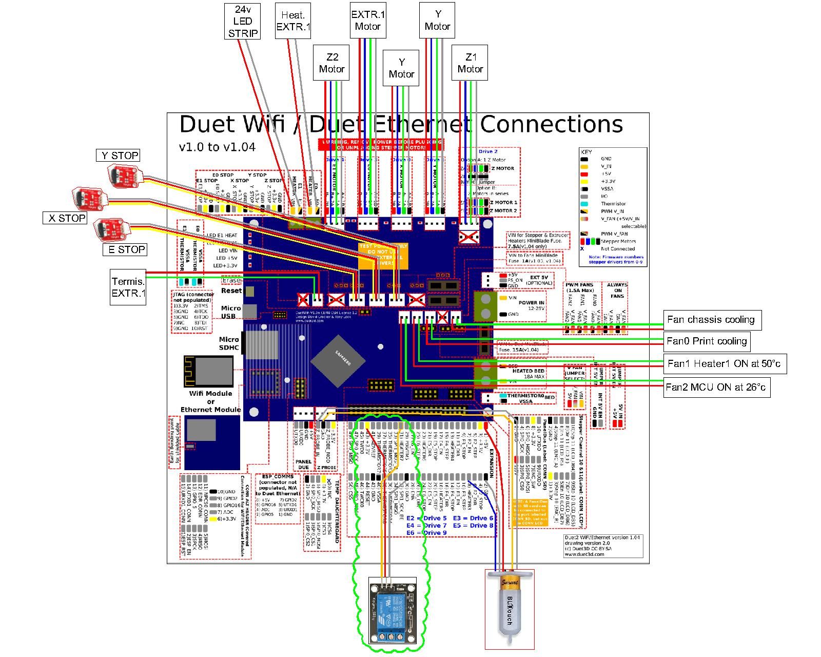
I connected the relay to the board, as shown in the figure, I added the command M950 F4 C "exp.heater7" Q500 in config.g and I wanted to switch the relay on and off through M42 P7 S1 and M42 P7 S0.
However, it is currently not working ...my wiring board :
Relay data sheet:
KEYES 5V Relay Module KY-019.pdfMy config.g:
; Configuration file for LONGER LK4 Pro - Duet2 Wi-Fi
; RepRap Firmware 3.3.0 RC1 - Duet Web Control 3.3.0 RC1
; Duet WiFi Server Version: 1.26 -  WiFi/Ethernet 3.3.0 RC1

; General preferences
G90                                            	; send absolute coordinates...
M83                                            	; ...but relative extruder moves
M550 P"LK4 DUET2 Wi-Fi 3.3.0 RC1"               ; set printer name

; Network
M552 S1                                        	; enable network

; Drives direction
M569 P0 S1                                     	; (ASSE X) 			physical drive 0 goes backwards
M569 P1 S1                                     	; (ASSE Y) 			physical drive 1 goes backwards
M569 P2 S1                                     	; (ASSE Z1)			physical drive 2 goes forwards
M569 P3 S0                                     	; (ESTRUSORE_E0) 	physical drive 3 goes backwards
M569 P4 S1										; (ASSE Z2)			physical drive 2 goes forwards
M584 X0 Y1 Z2:4 E3                              ; set drive mapping

; STEP/mm Interpolation (I1=WITH interpolation I0=WITHOUT interpolation)
M350 X16 I1										; Set Drive X to 16 microstepping WITH interpolation
M92 X160										; Set Drive X to 160 step/mm MOTORE (0.9 DEG)
M350 Y16 I1										; Set Drive Y to 16 microstepping WITH interpolation
M92 Y160										; Set Drive Y to 160 step/mm MOTORE (0.9 DEG)
M350 Z16 I1										; Set Drive Z to 16 microstepping WITH interpolation
M92 Z800										; Set Drive Z to 800 step/mm MOTORE (1.8 DEG)
M350 E16 I1										; Set Drive E to 16 microstepping WITH interpolation
M92 E92.60										; Set Drive E to 92.60 step/mm MOTORE (1.8 DEG)

; Drives Speed, Acceleration, Jerk
M205 X18 Y18 Z1 E15        	        			; JERK M205=>(mm/s^3) = M566=>(mm/min^3) per compatibilità con Marlin
M203 X12000.00 Y12000.00 Z960.00 E1800.00       ; Max SPEED (mm/min) X=200mm/S Y=200mm/S Z=16mm/S E=30mm/S
M201 X1000.00 Y1000.00 Z120.00 E3000.00         ; IN TEST - ACCELERATION (mm/s^2)
M906 X1500 Y1500 Z800 E1200 I30                 ; set motor currents (mA) il parametro I30 alla fine imposta al 30% il consuuno in St-By
M84 S25                                        	; S25= dopo 25secondi i motori entrano in modalità a basso consumo (St-By)

; Axis Limits
M208 X0 Y0 Z0 S1                               	; set axis minima
M208 X232 Y280 Z270 S0                         	; set axis maxima

; Endstops
M574 X1 S1 P"!xstop"                            ; configure active-high endstop for low end on X via pin xstop
M574 Y1 S1 P"!ystop"                            ; configure active-high endstop for low end on Y via pin ystop
M574 Z2 S1 P"!zstop"                            ; IN TEST ENSTOP Z HIGH Z2=endstop alto S1=interruttore normale P"!zstop"=nome della porta "!"=invertita
M591 D0 P2 C"e0stop" S1							; filament monitor connected to E0_stop
;M574 Z1 S1 P"!zstop"                           ; DISABILITATO PER PRESENZA BL-TOUCH
;M574 Z0										; No Z endstop

; Z-Probe
M950 S0 C"exp.heater3" 							; create servo pin 0 for BLTouch
M558 P9 C"^zprobe.in" H5 F400 T6000 			; set Z probe type to bltouch and the dive height +
G31 P500 X-7 Y-30 Z2.90							; set Z probe trigger value, (più alto è il valore Z più il nozzle è vicino al piatto)
M557 X5:230 Y0:280 S50							; define mesh grid (GRIGLIA 5x6)

; SETTING LETTO RISCALDATO
M308 S10 Y"mcu-temp" A"MAINBOARD"				; Abilità il monitoraggio temperatura della MCU
M308 S0 P"bedtemp" Y"thermistor" T100000 B4092 	; configure sensor 0 as thermistor on pin bedtemp "thermistor"
M950 H0 C"bedheat" T0                          	; create bed heater output on bedheat and map it to sensor 0
M307 H0 A149.0 C639.9 D1.4 V24.2 B0				; VALORE inserito DOPO AUTOTARATURA DEL LETTO
M140 H0                                        	; map heated bed to heater 0
M143 H0 S111                                   	; set temperature limit for heater 0 to 111C

;**** TEST COMANDO RELE' SU HEATER 7 E PORTA 7 ****
M950 F4 C"exp.heater7" Q500  					; allocate GPIO port 0 to heater3 on expansion connector, 500Hz
;M42 P7 S1  									; set 100% PWM on GPIO port 0 ( ON )
;M42 P7 S0  									; set 0% PWM on GPIO port 0 ( OFF )

; SETTING RISCALDATORE HOTEND
M308 S1 P"e0temp" Y"thermistor" T100000 B4092  	; configure sensor 1 as thermistor on pin e0temp
M950 H1 C"e0heat" T1                           	; create nozzle heater output on e0heat and map it to sensor 1
; M307 H1 R2.633 C164.3 D2.04 S1.00 V24.1		; (S1.00=PWM 100%) - VALORE inserito DOPO AUTOTARATURA DELL'ESTRUSORE (M303 H1 P1 S240)
M143 H1 S355                                   	; set temperature limit for heater 1 to 355°C

;LUCE LED su RISCALDATORE N°2 ("e1heat")
M950 F3 C"E1_HEAT" Q1000						;Fan 3 is connected to HEAT E1, si può inserire la frequanza PWM. Es. Q1000 è 1000Hz
M106 P3 S0.10            						;LED ON AL 10%
;M106 P3 S0.00									;PER SPEGNERE LED

; VENTOLA RAFFREDDAMENTO STAMPA
M950 F0 C"fan0" Q500                           	; create fan 0 on pin fan0 and set its frequency
M106 P0 C"FAN0 (Filo)" S0 H-1                  	; set fan 0 name and value. Thermostatic control is turned off

; VENTOLA RAFFR. ESTRUSORE SI ACCENDE A 50°C
M950 F1 C"fan1" Q500                           	; create fan 1 on pin fan1 and set its frequency
M106 P1 C"FAN1 (Estrusore)" S0.5 H1 T50         ; set fan 1 name and value. S1=100% S0.5=50% Thermostatic control is turned ON

; VENTOLA RAFFREDDAMENTO SCHEDA CON SENSORE TEMPERATURA
M308 S2 Y"drivers" A"DRIVERS"  					; configure sensor 2 as temperature warning and overheat flags on the TMC2660 on Duet
M308 S3 Y"mcu-temp" A"MCU" 						; configure sensor 3 as thermistor on pin e1temp for left stepper
M950 F2 C"fan2" Q100 							; create fan 2 on pin fan2 and set its frequency
M106 P2 H2:3 L0.5 X1 B0.3 T26:50 				; set fan 2 value  T26:50  velocità ventola L1=100% L0.50=50%

; VENTOLA TUNNEL ATTACCATA A USCITA NON PWM
;M950 F2 C"fan2" Q500                           ; create fan 2 on pin fan2 and set its frequency
;M106 P2 C"FAN2 (Tunnel)" S0.5 H-1              ; set fan 2 name and value. Thermostatic control is turned off

; Tools
M563 P0 D0 H1 F0                               	; define tool 0
G10 P0 X0 Y0 Z0                                	; set tool 0 axis offsets
G10 P0 R0 S0                                   	; set initial tool 0 active and standby temperatures to 0C

; Custom settings Ressurrect mode
M911 S21.5 R23.5 P"M913 X0 Y0 G91 M83 G1 Z5 E-3 F1000"  ;Autosalvataggio stampa per mancanza di corrente, sospende a 21v e riparte a 23.5v

; Miscellaneous
M912 P0 S-5.2									; parametro per tatare la temperatura della MCU (-5.2°C)
M575 P1 S1 B57600                              	; enable support for PanelDue (Necessario su RRF 3.0)
T0                                             	; select first tool ACTIVE
; END SCRIPT
thank you for the advice.
-
@gianluca
are you sure that you can switch this relays with 3.3VOk i have overlooked the datasheet from the relays and this is working between 5 and 12 V not with 3.3VHypercube-Evolution-Hybrid, Piezo Orion, Orbiter
Duet WiFi 1.02 or later + DueX5
RepRapFirmware for Duet 2 WiFi/Ethernet 3.4.0beta4 (2021-09-27 11:30:36)
Duet WiFi Server: 1.26
Duet Web Control 3.4.0beta4 (2021-09-27) -
@gianluca said in DUET 2 WIFI, RELAY CONTROL VIA GPIO:
I added the command M950 F4 C "exp.heater7" Q500 in config.g and I wanted to switch the relay on and off through M42 P7 S1 and M42 P7 S0.
With M950 F4 you have created a fan#4.
So you have to use M42 P4 S1 afterwards, for switching on the relay.Mankati FSXT+, DeltaTowerV2, E3D MS/TC
-
@gianluca
You can control that typ of relay with the PS_ON pin.(UTC+1)
-
@siam I tested the relay with the raspberry PI 4 and it works perfectly powered at 3v
-
@diy-o-sphere said in DUET 2 WIFI, RELAY CONTROL VIA GPIO:
@gianluca
You can control that typ of relay with the PS_ON pin.Interesting... could you give me some additional information on this solution?
I found the PS_ON pin, but what configuration could I use men config.g? -
@cosmowave said in DUET 2 WIFI, RELAY CONTROL VIA GPIO:
@gianluca said in DUET 2 WIFI, RELAY CONTROL VIA GPIO:
I added the command M950 F4 C "exp.heater7" Q500 in config.g and I wanted to switch the relay on and off through M42 P7 S1 and M42 P7 S0.
With M950 F4 you have created a fan#4.
So you have to use M42 P4 S1 afterwards, for switching on the relay.Correct, I try this evening...
-
@gianluca said in DUET 2 WIFI, RELAY CONTROL VIA GPIO:
could you give me some additional information on this solution
You can switch the pin with M80/M81.
Check the option for M81 maybe it is useful in your case.In RRF3 "pson" is available as a pin name for the 6HC . So configurable with M950.
But for the other boards the pin is not listed here.
I would have expected that this is uniform in RRF3, maybe @dc42 can confirm that.
I can't get why for those boards PS-ON is hard wired in the firmware.(UTC+1)
-
@gianluca that relay should work if you connect the relay connection labelled +5V to +5V on the Duet, instead of to +3.3V.
Duet WiFi hardware designer and firmware engineer
Please do not ask me for Duet support via PM or email, use the forum
http://www.escher3d.com, https://miscsolutions.wordpress.com -
@dc42
So the gpio pin is cappable to take 5V?
I thought since the logic runs on 3.3v no higher voltage should be applied. What is the limit?Edit:
Talking about expansion port.... -
@diy-o-sphere said in DUET 2 WIFI, RELAY CONTROL VIA GPIO:
So the gpio pin is cappable to take 5V?
No, it isn't. However, the schematic for that relay module shows that the SIGNAL input is used to feed a transistor and LED, and the 5V input provides the power to the relay, which is switched by the transistor.
Duet WiFi hardware designer and firmware engineer
Please do not ask me for Duet support via PM or email, use the forum
http://www.escher3d.com, https://miscsolutions.wordpress.com -
@dc42
Ok. That makes sense.... -
@cosmowave said in DUET 2 WIFI, RELAY CONTROL VIA GPIO:
@gianluca said in DUET 2 WIFI, RELAY CONTROL VIA GPIO:
I added the command M950 F4 C "exp.heater7" Q500 in config.g and I wanted to switch the relay on and off through M42 P7 S1 and M42 P7 S0.
With M950 F4 you have created a fan#4.
So you have to use M42 P4 S1 afterwards, for switching on the relay.I have tryed with:
M950 F4 C"exp.heater7" Q500 in config.g
and M42 P4 S1 to turn ON on console.
But pin 31 (heater7) is always on 0,0Volt.I also powered the relay at 5v (not at 3.3V as in the picture ) but nothing changes...
-
@diy-o-sphere said in DUET 2 WIFI, RELAY CONTROL VIA GPIO:
@gianluca said in DUET 2 WIFI, RELAY CONTROL VIA GPIO:
could you give me some additional information on this solution
You can switch the pin with M80/M81.
Check the option for M81 maybe it is useful in your case.In RRF3 "pson" is available as a pin name for the 6HC . So configurable with M950.
But for the other boards the pin is not listed here.
I would have expected that this is uniform in RRF3, maybe @dc42 can confirm that.
I can't get why for those boards PS-ON is hard wired in the firmware.Tested, all working good ... thanks.
Now I just have to work the relay with the GPIO on heater7 -
Note, the solution for correct run of relay is:
M950 F4 C"exp.heater7" Q500 (create a fan4)
M4106 P4 S1 (to turn ON the fan or relay).