Duet3D Logo Duet3D
    • Tags
    • Documentation
    • Order
    • Register
    • Login

    DuetWifi 2 and LIS3DH wiring

    Scheduled Pinned Locked Moved
    Duet Hardware and wiring
    10
    28
    4.4k
    Loading More Posts
    • Oldest to Newest
    • Newest to Oldest
    • Most Votes
    Reply
    • Reply as topic
    Log in to reply
    This topic has been deleted. Only users with topic management privileges can see it.
    • dc42undefined
      dc42 administrators
      last edited by

      @jay_s_uk said in DuetWifi 2 and LIS3DH wiring:

      @dc42 why is 3.3v needed when the adafruit LIS3DH has an onboard voltage regulator?
      The one I have here works fine with 5v

      So that the i2C signals have 3.3V signal levels.

      Duet WiFi hardware designer and firmware engineer
      Please do not ask me for Duet support via PM or email, use the forum
      http://www.escher3d.com, https://miscsolutions.wordpress.com

      nick9one1undefined 1 Reply Last reply Reply Quote 0
      • nick9one1undefined
        nick9one1 @dc42
        last edited by nick9one1

        93e2d09e-f3da-410b-89aa-e77fccf582de-image.png
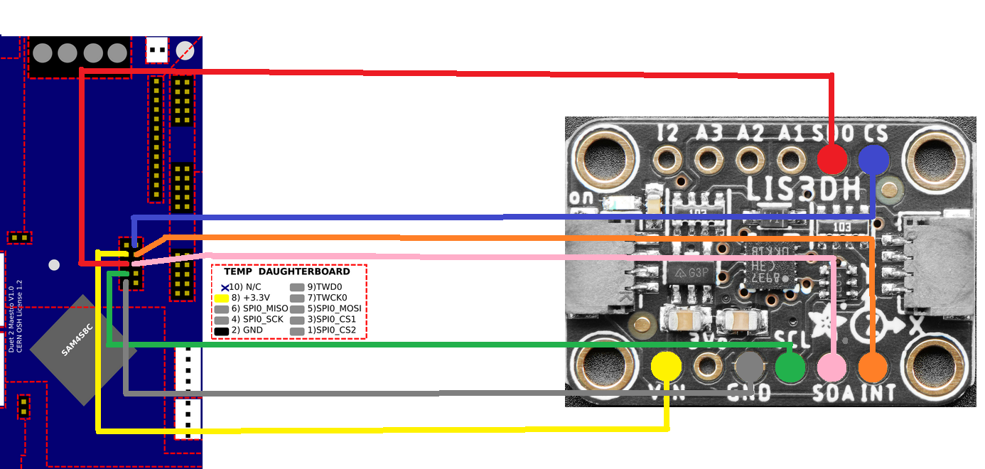
        I've wired it as per this diagram;

        fd4f77a7-bc53-47c4-af60-4db39f748043-image.png

        added this to config.g

        M955 P0 C"spi.cs3+spi.cs4"
        

        enabled the accelerometer plugin and have run the gcode;

        G1 X-50 G4 S2 M956 P124.0 S1000 A0 G4 P10 G1 X50 F20000
        

        but get this error;
        b7135c00-a532-4f73-ba21-d28e340dabe2-image.png

        If I try

        G1 X-50 G4 S2 M956 P0 S1000 A0 G4 P10 G1 X50 F20000


        (P0 instead of P124.0) it reports "Error: M956: Accelerometer not found"

        DIY-O-Sphereundefined SIamundefined 2 Replies Last reply Reply Quote 0
        • DIY-O-Sphereundefined
          DIY-O-Sphere @nick9one1
          last edited by

          @nick9one1
          In your wiring diagram +3.3V is connected to the wrong Vin pin of LIS3DH.
          And spi.cs3 + spi.cs4 are swapped.

          (UTC+1)

          sebkritikelundefined 1 Reply Last reply Reply Quote 1
          • sebkritikelundefined
            sebkritikel @DIY-O-Sphere
            last edited by

            @nick9one1 @diy-o-sphere said in DuetWifi 2 and LIS3DH wiring:

            @nick9one1
            In your wiring diagram +3.3V is connected to the wrong Vin pin of LIS3DH.
            And spi.cs3 + spi.cs4 are swapped.

            Yup, that looks to be the case (checked my crappy wiring diagram)
            https://forum.duet3d.com/topic/22878/software-package-3-3beta3-released/33?_=1621606715168

            Large(ish?) IDEX - 6HC, 1HCL
            Stratasys Dimension 1200es to 6HC Conversion

            nick9one1undefined 1 Reply Last reply Reply Quote 0
            • SIamundefined
              SIam @nick9one1
              last edited by

              @nick9one1

              @sebkritikel
              Your test code is wrong

              G1 X-50 G4 S2 M956 P124.0 S1000 A0 G4 P10 G1 X50 F20000
              

              must be

              G1 X-50 G4 S2 M956 P0 S1000 A0 G4 P10 G1 X50 F20000
              

              Hypercube-Evolution-Hybrid, Piezo Orion, Orbiter
              Duet WiFi 1.02 or later + DueX5
              RepRapFirmware for Duet 2 WiFi/Ethernet 3.4.0beta4 (2021-09-27 11:30:36)
              Duet WiFi Server: 1.26
              Duet Web Control 3.4.0beta4 (2021-09-27)

              1 Reply Last reply Reply Quote 0
              • nick9one1undefined
                nick9one1 @sebkritikel
                last edited by nick9one1

                @sebkritikel

                thanks, swapped those pins and got further ๐Ÿ™‚
                this is the wiring diagram now
                117dd8e1-1f83-46cb-a271-13a6b299c33a-image.png

                G1 X-50 G4 S2 M956 P0 S1000 A0 G4 P10 G1 X50 F20000
                

                now generates a csv, but also gives an error..

                e7d63713-fac8-48d9-9362-930d2c4ba149-image.png

                csv here:
                https://1drv.ms/u/s!AgN3RlWvEHCokZAkg_o_XZeWuFRT7Q?e=i2IFTZ

                sebkritikelundefined dc42undefined 2 Replies Last reply Reply Quote 0
                • sebkritikelundefined
                  sebkritikel @nick9one1
                  last edited by

                  @nick9one1 said in DuetWifi 2 and LIS3DH wiring:

                  @sebkritikel

                  thanks, swapped those pins and got further ๐Ÿ™‚
                  this is the wiring diagram now
                  117dd8e1-1f83-46cb-a271-13a6b299c33a-image.png

                  G1 X-50 G4 S2 M956 P0 S1000 A0 G4 P10 G1 X50 F20000
                  

                  now generates a csv, but also gives an error..

                  e7d63713-fac8-48d9-9362-930d2c4ba149-image.png

                  csv here:
                  https://1drv.ms/u/s!AgN3RlWvEHCokZAkg_o_XZeWuFRT7Q?e=i2IFTZ

                  May be some useful info in these threads regarding your latest error (and the associated โ€˜garbageโ€™ in the csv)

                  https://forum.duet3d.com/topic/23021/duet3-6hc-gcode-inside-accelerometer-results/7?_=1621647165826

                  https://forum.duet3d.com/topic/23013/is-there-a-way-to-debug-accelerometer-connection-issues/22?_=1621647372962

                  Large(ish?) IDEX - 6HC, 1HCL
                  Stratasys Dimension 1200es to 6HC Conversion

                  1 Reply Last reply Reply Quote 0
                  • dc42undefined
                    dc42 administrators @nick9one1
                    last edited by

                    @nick9one1 see the five bullet points at the end of https://duet3d.dozuki.com/Wiki/Accelerometers#Section_Retrieving_the_data.

                    Duet WiFi hardware designer and firmware engineer
                    Please do not ask me for Duet support via PM or email, use the forum
                    http://www.escher3d.com, https://miscsolutions.wordpress.com

                    nick9one1undefined 1 Reply Last reply Reply Quote 0
                    • nick9one1undefined
                      nick9one1 @dc42
                      last edited by nick9one1

                      @dc42
                      thanks. I've tried a coupe of different cards with the same result.

                      The card I'm using is 100MB/s UHS class 1.

                      I've dropped the sample rate down to 100, and only for the X axis so the gcode looks like this;

                      G1 X-50 G4 S2 M956 X P0 S100 A0 G4 P10 G1 X50 F20000
                      

                      the csv contains;
                      could it still be a wiring issue?

                      a6194c08-0e2d-484c-ad29-342b2b5486eb-image.png

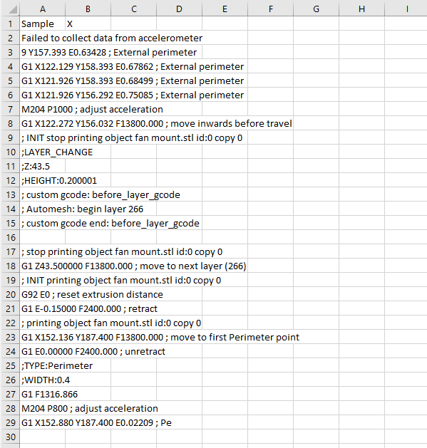
                      this is how its currently wired
                      2f9f8d1b-7c74-4e2f-987a-78749dd511c7-image.png

                      dc42undefined 1 Reply Last reply Reply Quote 1
                      • dc42undefined
                        dc42 administrators @nick9one1
                        last edited by

                        @nick9one1 your post at 02:20 UK time in which you posted a link the the .csv file shows that it has successfully collected the first 39 samples. That suggests that the wiring was at least working some of the time.

                        I suggest you install RRF 3.3RC2 and reduce the SPI frequency to 2MHz or 1MHz. There is a M955 parameter to do that in RC2.

                        Duet WiFi hardware designer and firmware engineer
                        Please do not ask me for Duet support via PM or email, use the forum
                        http://www.escher3d.com, https://miscsolutions.wordpress.com

                        nick9one1undefined 2 Replies Last reply Reply Quote 1
                        • nick9one1undefined
                          nick9one1 @dc42
                          last edited by

                          @dc42 thanks I'll try that next.

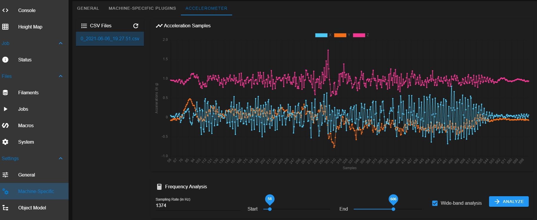
                          Earlier I did manage to run it again and get what looks like a complete csv of 100 samples with no errors.

                          https://1drv.ms/x/s!AgN3RlWvEHCokZAlu3J5zuYliA661w?e=bRuxIp

                          but it seems very temperamental. Sometimes giving me some results with errors, sometimes none.

                          1 Reply Last reply Reply Quote 0
                          • nick9one1undefined
                            nick9one1 @dc42
                            last edited by

                            @dc42

                            I've installed RC2 but cant see any documentation on how to set the new Q parameter?

                            dc42undefined 1 Reply Last reply Reply Quote 0
                            • dc42undefined
                              dc42 administrators @nick9one1
                              last edited by

                              @nick9one1 see https://duet3d.dozuki.com/Wiki/Gcode#Section_M955_Configure_Accelerometer. The default SPI frequency used to be 4MHz in 3.3beta3 but is 2MHz in 3.3RC2.

                              Duet WiFi hardware designer and firmware engineer
                              Please do not ask me for Duet support via PM or email, use the forum
                              http://www.escher3d.com, https://miscsolutions.wordpress.com

                              1 Reply Last reply Reply Quote 0
                              • nurooundefined
                                nuroo
                                last edited by

                                @nick9one1
                                Thank you for posting your questions and asking for help interpreting the instruction for using this sensor with duet2 board. Some pinout diagrams differ in pin names then instructions. This made the instructions confusing to me.

                                "On Duet WiFi, Duet Ethernet and Duet Maestro all the SPI CS pins have interrupt capability, so you can use any two spare CS pins on the daughter board connector. For example, on a Duet WiFi or Duet Ethernet you could connect the accelerometer CS pin to SPI.CS3, and the INT1 pin to SPI.CS4. [Note: if you already have one daughter board plugged into the main board and you wish to connect to SPI.CS3 and SPI.CS4 on the top of that daughter board, the daughter board passes SPI.CS3 and SPI.CS4 to the pin positions directly above the SPI.CS1 and SPI.CS2 pins on the main board. This is so that a second daughter board stacked on top automatically uses SPI.CS3 and SPI.CS4 instead of SPI.CS1 and SPI.CS2.] Use this command to tell RRF about the accelerometer:"

                                Anyway your updated diagram is gold. Something like it should really be included in the instructions.
                                Until reprap has something as informative - these two videos using it with klipper helped me understand the concepts and practical uses of using an accelerometer on your 3d printer:
                                https://youtu.be/OoWQUcFimX8
                                https://youtu.be/IezqWVZZ_iI

                                Hopefully I can get this specific sensor by the time 3.4 is released.

                                1 Reply Last reply Reply Quote 0
                                • nurooundefined
                                  nuroo
                                  last edited by nuroo

                                  This post got me up and running on a railcore. Had to change some pins in config setup to use daughter board spi. Im getting data thru the plugin as well. Looking forward to rrf 3.4
                                  accelALL.jpg

                                  1 Reply Last reply Reply Quote 0
                                  • muleundefined
                                    mule
                                    last edited by

                                    Just a quick info:
                                    The picture of the adafruit LIS3DH on https://duet3d.dozuki.com/Wiki/Accelerometers is misleading because the V3.3 from the duet is connected to 3Vo (Output) instead of the VIN (Input) pin. Maybe it is better to remove it.

                                    droftartsundefined 2 Replies Last reply Reply Quote 1
                                    • droftartsundefined
                                      droftarts administrators @mule
                                      last edited by

                                      @mule Thanks. Do you mean this one? https://d17kynu4zpq5hy.cloudfront.net/igi/duet3d/Y1YiEWyeIEP5qi4Q
                                      I see what you mean. I'll try and get @dc42 to take another picture. For now I'll put a note on the page.

                                      Ian

                                      Bed-slinger - Mini5+ WiFi/1LC | RRP Fisher v1 - D2 WiFi | Polargraph - D2 WiFi | TronXY X5S - 6HC/Roto | CNC router - 6HC | Tractus3D T1250 - D2 Eth

                                      1 Reply Last reply Reply Quote 0
                                      • droftartsundefined
                                        droftarts administrators @mule
                                        last edited by

                                        @mule From @dc42:

                                        connecting +3.3V from Duet to 3V0 is correct. In practice, connecting it to Vcc works too.
                                        Connecting to Vcc would be necessary if we were using 5V supply

                                        So I'll leave as is.

                                        Ian

                                        Bed-slinger - Mini5+ WiFi/1LC | RRP Fisher v1 - D2 WiFi | Polargraph - D2 WiFi | TronXY X5S - 6HC/Roto | CNC router - 6HC | Tractus3D T1250 - D2 Eth

                                        1 Reply Last reply Reply Quote 0
                                        • muleundefined
                                          mule
                                          last edited by

                                          For me it did not work to connect +3.3V from duet to the output of the adafruit board. Maybe there are different boards with different layouts being sold by adafruit?

                                          nick9one1undefined 1 Reply Last reply Reply Quote 0
                                          • nick9one1undefined
                                            nick9one1 @mule
                                            last edited by

                                            Glad my diagram helped!

                                            I never got it working on the Duet2 WiFi, but have recently upgraded to a 3 Mini 5+ and trying again...

                                            https://forum.duet3d.com/topic/25904/mini-3-5-and-lis3dh-wiring/2

                                            1 Reply Last reply Reply Quote 0
                                            • First post
                                              Last post
                                            Unless otherwise noted, all forum content is licensed under CC-BY-SA