Tinkering of building HD Voron
-
@paulhew i have built a printer using this kind of design. You can build it without being overconstraint. But you need to think about each z axis as independant axis. My 2 y axis are fixed in the back and they are just put on the front z axis.
You can't really make 4 identical z axis.
But it's somerhing you can make.
For my printer, it was easier to keep the bed stationary. 7kilos is enough...
-
Exactly, I do not want a heavy bed with 240VAC moving around.
-
@tecno said in Tinkering of building HD Voron:
Did consider 3 screws but I don´t think 4 will give any problems and certainly not noise as Z moves layer by layer
Just watched this Teaching Tech about the Rat Rig he builds. Very interesting Z design, with 3 leadscrews and delta like magnetic couplers to avoid over constraining.
-
If you're set on a raising gantry+screws, switch to 3 screws and couple them very carefully to make sure that they're allowed to move. Voron uses belts which allows some compliance when raising/lowering.
I suspend 11kg bed (622x622 print area, 3/8" thick mic6) on 3 screws+3mgn12's. Works great without issue. just need to use thrust washers to keep the load off the Belleville spring in the z motors, and kinematic coupling (I chose maxwell) for the bed joints. It allows for live tramming.
-
@luke-slaboratory said in Tinkering of building HD Voron:
I suspend 11kg bed (622x622 print area, 3/8" thick mic6) on 3 screws+3mgn12's. Works great without issue. just need to use thrust washers to keep the load off the Belleville spring in the z motors, and kinematic coupling (I chose maxwell) for the bed joints. It allows for live tramming.
Did you ever post a picture of this monster and if so do you have a link to it/them?
-
https://github.com/lukeslaboratory/Stablebot-Core <- rep with picture, me for scale. Will be re-liscensing to remove the "NC" to make it fit better with rest of the OS community.
I have significant updates I need to post - I went through and gave it quite a few QOL touches (gantry harnessing!) as I've built a smaller version (400x400x450) and am planning to build a 500x500x550 version as well, so stay tuned.
https://imgur.com/xWmedaV <- the 400mm version that has the updated wire routing+other QOL, but the CPAP cooling hasn't been tamed yet. Its currently printing a brain box to hide some of the nasty wiring that still hangs out on this demo unit, which is running a Duet3 mini with Klipper.
Will be toolchanging sometime this summer, but testing single-tool speed runs including getting a magnum+ from slice in a few weeks.
-
@luke-slaboratory, thank you !
-
@zapta
I like the idea behind the magnetic couplers, but why do they secure the mags with bolt & nuts, when they later use dowel pins?
There are stronger solid magnets they could place in there and simply secure them with the pins.
Plus, do they have at least one corner fixed and the others floating? (Video doesn't show)It's funny how the constraint-discussion blossoms up every now and then, but be forgotten too soon...
-
@o_lampe interesting comment re one corner being fixed. I've been wondering how the jubilee gets away without apparently fixing anything. There are springs between the kinetic coupling and the bed but from what I can see there is no fixed point.
-
@jens55
Do you have a link to the jubilee? The vid was about RatRig -
@o_lampe, don't know how much you can gleen from the documentation but here you go:
https://www.jubilee3d.com/index.php?title=Main_Page
I have not installed a build plate on mine yet but it is supported by 3 points that are balls beneath the build plate and dowel pins on the z rails. The only thing that seems to hold things together is gravity and some tiny springs.
-
@jens55
Thanks, interesting build, too. Although I don't like the single-side supported belt idlers....In the top view you can see that the axis of the dowel pins of the front towers are not parallel but 120° aligned. That way there's only one drag-free position for all three balls to drop in.
-
@o_lampe, while I realize that the dowels are aligned in three positions that are 120 degrees off from each other, my gut wants to say that at least one point has to be fixed. It obviously doesn't need to have a fixed anchor and it supposedly works very well (the tool head and the individual tools join in a similar method that is supposedly repeatable to some ridiculous level of precision) .... but gut feeling says that there must be one fixed position. I just haven't sat down to facilitate a discussion between mind and gut yet.
-
@jens55 said in Tinkering of building HD Voron:
gut feeling says that there must be one fixed position
That's the trap many people fall in (as does the thread owner). And when one fix-point is good, many points are better
")
I checked the RatRig video again, and they also use the 120° method.
So I take back my question about a fix-point.//edit just digged out an old clip of mine, where a 'least' extrusion frame can be seen.
Only 3 vertical and 3 horizontal extrusions; a single linear rail for the cantilevered bed. But it all worked out, because of the dual roller constraint. It was just a demo, but a few solutions could be used for a real printer build. -
The 3 point bed support is intended to be a kinematic mount that allows the bed to expand without it putting any lateral force on the supports. The bed plate literally sits on top of the balls. There's theoretically no need to hold it down but if you transport the machine and tilt it the plate may fall. So adding springs prevents that (and maybe some rattling when the Z axis is being slewed). Of course, you don't want the bed moving around when you are prying prints off it.
As the plate heats up it expands in all directions. The kinematic mount, if it is to work properly, has to have the "rails" that the balls contact lined up so they point to the center of the bed. If they are accurately aimed, the center of the bed won't move as the plate expands around it. This is called a Maxwell kinematic coupling.
There is also a Kelvin kinematic coupling (which is what I use in my printer). It has a "fixed" reference point, one slot, and one flat slide. I used this type mount because the slot, which is aligned with the reference point, runs parallel to the milling machine X axis that is used to cut the slot (and the rest of the plate), so it's a no-brainer. The third point simply supports the smooth plate from the underside. As the plate expands, the reference point doesn't move, the bed expands toward the slot and is free to slide in that direction only, and can slide in X and Y on the third point. Hold down springs are used at each of the three support points.
Either one works fine, as the bed plate remains at a constant temperature while printing. Of course, if you lose power and the bed cools off during a print, the ability to resume printing depends on whether the Z axis has moved and whether the print has let go of the bed.
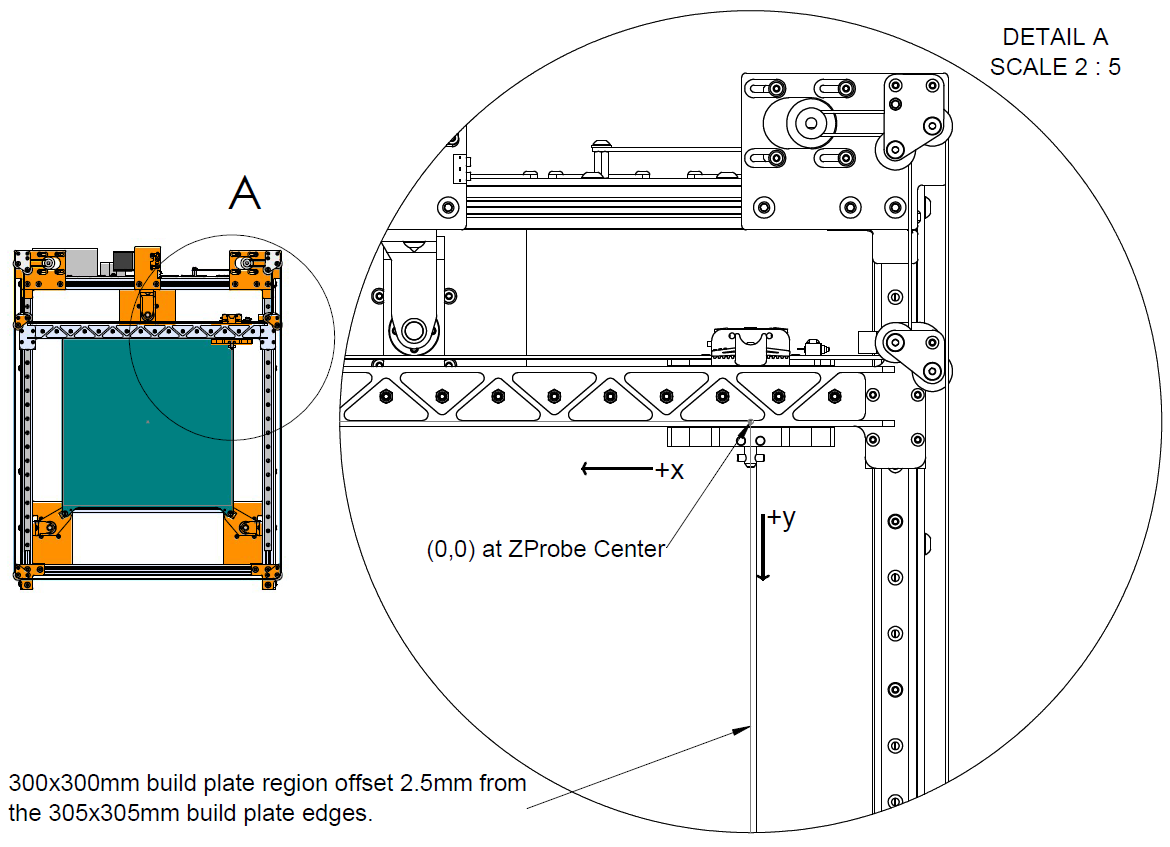
I like to use the dead center of the bed for both the printer's and bed's origins. It makes configuration, macro writing, and slicer setup super easy, and makes the gcode somewhat portable from one machine to another (that is set up with the origin at the center).
-
@mrehorstdmd, interesting! I did not know about the second type of kinematic coupling. Thanks for that explanation.