New heated enclosure printer
-
@t3p3tony Thanks! I understand about voiding the warranty. Are the driver warnings anything to be concerned with in terms of damage to the board or printing issues? I don't want to open a can of worms but being a little old school and given an equal choice, prefer a hardware solution to a software one.
-
@coseng The warnings will be the stepper drivers complaining the is an open circuit between the motor connector pins. This should not cause any damage but be aware those pins will be "live" when the stepper driver is enabled so shorts across them will probably damage the board.
I need to check with @dc42 if M569 R-1 can be used to disable the internal driver without disabling the step and direction signals.
-
@t3p3tony OK. I'll put empty connector housings on the stepper outputs to be sure nothing will contact them. 'M569 R-1' working would be nice but is not necessary. I'll place an order with Filastruder for all the parts. Thanks for the help.
-
@coseng if you leave the motor currents set at zero in RRF then you won't get any warnings about motors being disconnected.
Duet WiFi hardware designer and firmware engineer
Please do not ask me for Duet support via PM or email, use the forum
http://www.escher3d.com, https://miscsolutions.wordpress.com -
@dc42 OK, thanks. That seems to about cover it. I have all the hardware on order and will start to draw up the mechanicals and post some progress as it goes. I'm sure there will be more questions along the way!
-
@t3p3tony Can you give me a hand confirming which pins on the Duet2 expansion board 50 pin connector get connected to the enable, step, and direction pads on the Duet 6HC? From the Duet2 pinout, I think it is DX_STEP on 6HC to EX_STEP on EBB, DX_DIR on 6HC to EX_DIR on EBB, DX_DIAGO on 6HC to EX_EN on EBB, but what about the EX_STOP pin on the EBB?
Thanks,
Chris -
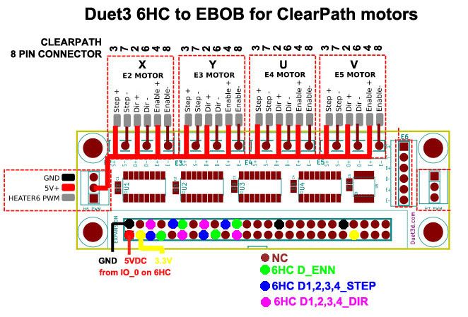
6HC DxSTEP - > EBOB EySTEP
6HC DxDIR - > EBOB EyDIR
6HC DRIVER_ENN -> EBOB EzENThere is only one Enable line on the 6HC as the individual onboard drivers are controlled over SPI so your external drivers will be enabled en masse.
Diag0 is an output from the onboard driver to the main processor so do not connect to that,
the EBOB does not break out the endstop pins from the 50 way connector.
Sources:
-
@t3p3tony OK, I will split the single 6HC enable signal to the 4 external stepper drivers. I am OK with using the onboard endstop connectors unless I am not understanding you. the motors with integrated drivers do not have endstop functionality.
One more question. For the EBOB wiki: The Duet Expansion Breakout Board uses a differential output signal of -3.6V to +3.6V.........for those few drivers that really do need 5V........
Do I need to do this? The inputs on the motor driver are 5-24VDC.
'5V differential outputs are not directly compatible with ClearPath inputs because differential drivers' guaranteed output voltage swing is typically not guaranteed to meet the ClearPath input minimum input voltage requirements. While differential drivers may work initially, they may fail over time as the environment changes, i.e. the motor heats up, components age, and so forth. This can result in erratic operation that is difficult to debug.'
https://www.teknic.com/files/downloads/clearpath_user_manual.pdf P.43-47.
-
@coseng regarding the 5V signal level question, yes as the notes say if the driver needs 5V then connect +5V to the 5V supply on the EBOB and connect the STEP(-), DIR(-) etc signals to the corresponding terminals on the clearpath as shown on page 47 of the datasheet.
-
@t3p3tony OK, so I think this is what you mean:
-
@coseng, just to make yo aware: using the DRIVERS_ENN line to feed to the EBOB Enable inputs, the drivers will get enabled as soon as VIN power is stable and the on-board drivers have been initialised. They will be disabled only when VIN power to the 6HC is removed.
You will need to select the polarity of the Enable outputs to be correct for your servos. DRIVERS_ENN will go low to enable the drivers. If you are using single ended 5V drive, then connect ENA+ of your servo to +5V, and ENA- to either Enable+ or Enable- on the EBOB, whichever gives the correct polarity.
Duet WiFi hardware designer and firmware engineer
Please do not ask me for Duet support via PM or email, use the forum
http://www.escher3d.com, https://miscsolutions.wordpress.com -
@dc42 Thanks for pointing that out. In that case, I may want to feed the EBOB +5V from IO_0's io0.out instead of 5V_EXT so that the enable signal to the external drivers is activated at a predetermined and repeatable time.
The DRIVERS_ENN line will go low quickly after power on, but the EBOB board won't be powered, so can't convert the enable signal to the output connector pins until io0.out is told to go high.
The motors seem to want the 75VDC connected first, then the enable signal. The motor 75VDC power supply could be switched on by a contactor from the main power switch, then after the 6HC boots up it can set io0.out to +5v. Or maybe that is only done when about to start printing.
-
I have all the hardware and mechanicals here and am starting the teardown of the temp chamber. The heater/fans were a cool design with a motor using an extended shaft to pass though the insulated wall. there was a small fan on the motor side to cool it and on the hot side there were two heater elements at the intake of the squirrel cage rotor. It is a pretty clean design and could be easily DIY duplicated with a simple motor shaft and a couple of elements from a heat gun.

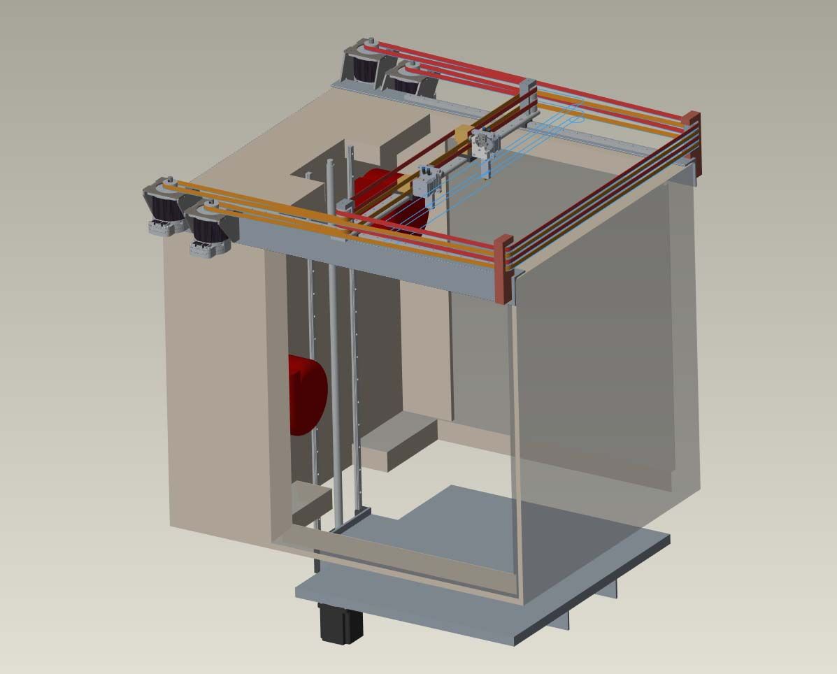
Starting on the mechanical details next. Did a bunch of internet browsing so not to reinvent the wheel and ended up with something similar to the a stacked version of the Digital Dentist's recommendations, which are pretty damn good.
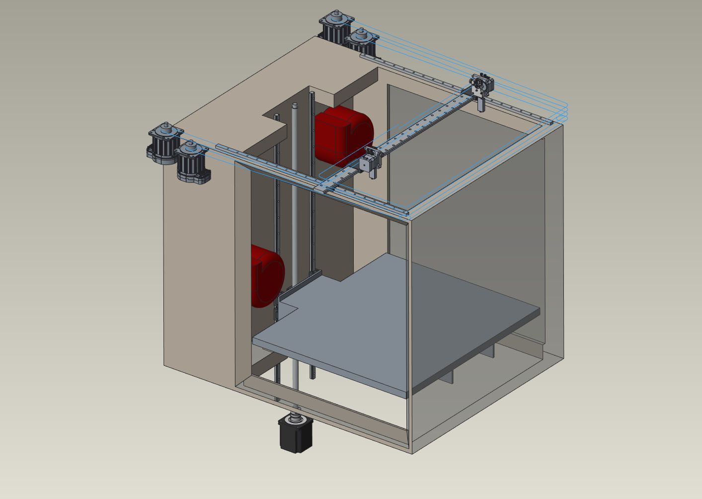
The overall rail and carriage layout is done, now to draw up a few brackets and mounting plates to ensure it is all easily align-able and rigid when tightened down. All of the mechanicals are outside of the heated chamber to keep their thermal expansion minimized. The carriage and table support inside the chamber will be made from high temp carbon fiber sheet to minimize thermal growth of the moving mechanism and the aluminum/Keenovo heated build plate assembly will float on a support system to allow it to freely expand without binding. CF has a low CTE and a really high modulus so the cantilever carriage should be plenty rigid and very stable.
-
@jens55 I run a custom built chilled liquid cooled core-xy machine in a heated chamber with a BL-touch in 100-150C all the time with no issues. I recently upgraded to a 6mm ceramic glass bed from borosilicate, and the ceramic glass has a near perfect uniformity I don’t bother with the mesh bed leveling anymore. I started using feeler gauges between the nozzle and glass on the 4 bed adjusters and it’s been incredibly consistent first layers/line widths. So depending on how you setup your machine it might now be worth the 40 dollars for a fancy end stop.
-
@jps0284 Sounds like an interesting machine. What material do you print with it? Since bed levelling and a BL are pretty simple and already part of the design it is not a hassle to include.
What exactly does a fancy end stop entail?
-
@coseng @coseng I mostly print Polycarbonate, CFPC, High temp CF nylon, CF PEI. Im constantly tweaking my machine and after I switched from dual z lead screws to 1204 ball screws with more ridged build plate and a ceramic glass bed, once I leveled it with the feeler gauges the bl touch really doesn't offer much other than act as a fancy end stop. It also seemed like there was some
Inconsistencies with the measurement read outs at times, when I relied on the accuracy of the bl touch is when I seemed to have more time diagnosing layer height issues than doing it manually. -
@jps0284 BL Touch do say that it is only good to around 65C, so I am not surprised you were having measurement inconsistency at higher temps.
-
@3dpmicro Thanks for the info, Centro was the low quote from a few places for the bellows and now is on order.
-
Making some progress with the build. It is all stripped down, the lower section is newly insulated, and the top section has the pass-through hole in the bottom cut. That hole makes it one big chamber for almost 1m of Z travel, 0.68m and 0.72m for XY.

We'll flip it and cut the same hole in the top which the motion subassembly will drop down into and be closed off with a y-axis bellows.
Each motor pair/y axis rail/belt pulley assembly base will be a rigid steel 2x3" angle that will be milled flat and mounted along the top of the housing. Each of these will be carefully aligned to keep everything parallel. The Z axis stage will be a separate assembly that bolts to the back wall of the chamber.
-
@coseng looking good. Not sure what chamber temp you're shooting for but consider mineral wool board if the fiberglass is insufficient. In my testing A 1" thick piece with foil backing reduced 210c on the foil side to 55c on the outside. Consider also that thermal expansion will have an effect on your motion system. May require realignment once it is up to temp.
Can you give us an idea on the cost of the bellows for the sizes you ordered?