Sensorless Homing not Working on Custom Built Printer
-
@gloomyandy Did that this morning, they are in the correct mode.
-
@3dmakerkid said in Sensorless Homing not Working on Custom Built Printer:
@gloomyandy Did that this morning, they are in the correct mode.
Yes but you have changed things since then (you added the V100), running M569 P0 will show you the speed at which the switchover takes place and will confirm that the v100 is correct (seems a little high to me, you really want to either stay in stealthchop all of the time or switch at a low velocity, switching modes at a high speed is usually not a good idea).
Probably worth reposting your current config.g and your modified x and y homing files if you are still having problems.
-
@gloomyandy You're right, I ran it again and got a good response back, said that it stayed enabled until 75mm/s, I changed the V value to 50 and it's now reporting 150mm/s switchover speed, which I think is acceptable. Anyways, here are my updated files.
@3dmakerkid said in Sensorless Homing not Working on Custom Built Printer:
@phaedrux I got X to home, so moved on to Y, got Y to home successfully, and now X won't home correctly, I didn't change anything.
Also not sure what is happening here.
config.g
; executed by the firmware on start-up ; ; generated by RepRapFirmware Configuration Tool v3.2.3 on Wed Jun 30 2021 18:28:51 GMT-0400 (Eastern Daylight Time) ; General preferences G90 ; send absolute coordinates... M83 ; ...but relative extruder moves M550 P"3DPrinter" ; set printer name ; Network M552 S1 ; enable network M586 P0 S1 ; enable HTTP M586 P1 S0 ; disable FTP M586 P2 S0 ; disable Telnet ; Drives M569 P0.0 S0 V50 ; physical drive 0.0 goes forwards M569 P0.1 S1 V50 ; physical drive 0.1 goes forwards M569 P0.2 S0 V50 ; physical drive 0.2 goes forwards M569 P0.3 S1 V50 ; physical drive 0.3 goes forwards M569 P0.4 S0 V50 M584 X0 Y1 Z2:4 E3 ; two Z motors connected to driver outputs Z and E1 M350 X16 Y16 Z16 E16 I1 ; configure microstepping with interpolation M92 X100.00 Y100.00 Z1600.00 E409.00 ; set steps per mm M566 X900.00 Y900.00 Z60.00 E120.00 ; set maximum instantaneous speed changes (mm/min) M203 X6000.00 Y6000.00 Z180.00 E1200.00 ; set maximum speeds (mm/min) M201 X500.00 Y500.00 Z20.00 E250.00 ; set accelerations (mm/s^2) M906 X400 Y800 Z800 E800 I30 ; set motor currents (mA) and motor idle factor in per cent M84 S30 ; Set idle timeout ; Axis Limits M208 X0 Y0 Z0 S1 ; set axis minima M208 X250 Y210 Z210 S0 ; set axis maxima ; Endstops M574 X1 S3 ; configure sensorless endstop for low end on X M574 Y1 S3 ; configure sensorless endstop for low end on Y M915 X S50 R1 F0 ; M915 Y S3 R1 F0 ; ; Z-Probe M671 X0:125:250 Y0:105:210 S10 ; Locations left, center, right M558 P8 C"121.io2.in" H0.7 F1000 T6000 A20 S0.005 ; PINDA set Z probe type to switch and the dive height + speeds M308 S2 P"121.temp2" A"PINDA" Y"thermistor" T100000 B3950 G31 P500 X-3.20 Y0 Z2.5 ; set Z probe trigger value, offset and trigger height M557 X15:4215 Y15:195 S20 ; define mesh grid ; Heaters M308 S0 P"temp0" Y"thermistor" T100000 B4138 ; configure sensor 0 as thermistor on pin temp0 M950 H0 C"out0" T0 ; create bed heater output on out0 and map it to sensor 0 M307 H0 B1 S1.00 ; enable bang-bang mode for the bed heater and set PWM limit M140 H0 ; map heated bed to heater 0 M143 H0 S120 ; set temperature limit for heater 0 to 120C M307 H0 R0.295 C369.7 D10.32 S1.00 V23.8 ; control parameters for H0 M308 S1 P"temp1" Y"thermistor" T100000 B4138 ; configure sensor 1 as thermistor on pin temp1 M950 H1 C"out1" T1 ; create nozzle heater output on out1 and map it to sensor 1 M307 H1 B0 S1.00 ; disable bang-bang mode for heater and set PWM limit M143 H1 S280 ; set temperature limit for heater 1 to 280C ; Fans M950 F0 C"out5" Q500 ; create fan 0 on pin out5 and set its frequency M106 P0 S1 H1 T45 ; set fan 0 value. Thermostatic control is turned on M950 F1 C"out6" Q500 ; create fan 1 on pin out6 and set its frequency M106 P1 S1 H-1 ; set fan 1 value. Thermostatic control is turned off ; Tools M563 P0 D0 H1 F0:1 ; define tool 0 G10 P0 X0 Y0 Z0 ; set tool 0 axis offsets G10 P0 R0 S0 ; set initial tool 0 active and standby temperatures to 0C ; Dual Z steppers M671 X-20:220 Y0:0 S0.5 ; leadscrews at left (connected to Z) and right (connected to E1) of X axis M208 X-5:205 Y0:200 ; X carriage moves from -5 to 205, Y bed goes from 0 to 200 ; Custom settings are not defined``` homex.g ``` M400 M913 X70 Y70 ; drop motor current to 70% M400 G91; relative positioning G1 H2 Z10 F3800 ; lift Z realtive to current position G1 H1 X-320.5 F3800; move quickly to X axis endstop and stop there G1 H2 Z-10 F3800 ; lower Z again G90 ; absolute positioning M400 M913 X100 Y100 ; return current to 100% M400``` homey.g ``` ; homey.g ; called to home the Y axis ; ; generated by RepRapFirmware Configuration Tool v3.2.3 on Wed Jun 30 2021 18:28:51 GMT-0400 (Eastern Daylight Time) M400 M913 X70 Y70 ; drop motor current to 70% M400 G91; relative positioning G1 H2 Z10 F3800 ; lift Z realtive to current position G1 H1 Y-320.5 F3800; move quickly to X axis endstop and stop there G1 H2 Z-10 F3800 ; lower Z again G90 ; absolute positioning M400 M913 X100 Y100 ; return current to 100% M400``' -
@3dmakerkid said in Sensorless Homing not Working on Custom Built Printer:
M915 X S50 R1 F0 ;
M915 Y S3 R1 F0 ;Are these correct? Seems a little odd to have such a big difference in the stall sensitivity for X and Y?
-
@gloomyandy Oops yeah, that's me trying different numbers to try and get X to home correctly again, it did work at the default (3), and both extremes, -50 and +50.
-
If these are 0.9 motors you may need to use a higher M915 H value, and/or a higher speed during the homing move.
Hnnn (optional) Minimum motor full steps per second for stall detection to be considered reliable, default 200 (try 400 for 0.9deg motors)
Have you done the calculations to find your optimal H value?
Minimum recommended speed for stall detection
A rough figure for the minimum speed in full steps per second (M915 H parameter) for which you should be able to get reliable stall detection is given by this formula:Hmin = full_steps_per_rev * rated_current * actual_current/(sqrt(2) * pi * rated_holding_torque)
where full_steps_per_rev is 200 or 400 (for 1.8 or 0.9deg motors), currents are in amps, and holding torque is in Nm. From this it can be seen that stall detection at low speeds is easier at lower motor currents. This is one reason why motor current is often reduced during stall-detect homing,Attempt to keep the speed above 40mm/s.
-
@phaedrux I got 36 for the calculation, not sure if that's correct, I'm using LDO Motors 1.8 degree steppers with 0.5NM of holding torque and running at .4 amps. I tried turning the speed up to 5000mm/min from 3800mm/min, but that did not help. The Y axis is still homing successfully with the exact same settings. Here's a video of my X-axis attempting to home, apologies for the awful video quality. https://www.youtube.com/watch?v=61zpuZgwNH0
-
If you provide me with these values I can calculate it for you in my spreadsheet.
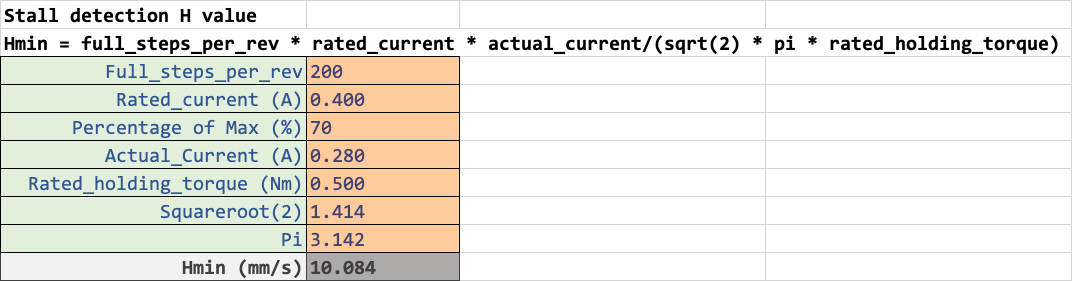 Stall detection H value
Hmin = full_steps_per_rev * rated_current * actual_current/(sqrt(2) * pi * rated_holding_torque)
Full_steps_per_rev 200
Rated_current (A) 0.400
Percentage of Max (%) 70
Actual_Current (A) 0.280
Rated_holding_torque (Nm) 0.500
Squareroot(2) 1.414
Pi 3.142
Hmin (mm/s) 10.084Guessing at some of your values I get this. What is the actual rated current of your motor? And you're running it at only 400ma and then reducing further by 70%.
-
@phaedrux I got all axis homing, ended up having to change the amount of current used for X homing to 90% of 400mA instead of 70%. Now I have another issue, I can not move the axis to their limits. If I home all, then tell X to go to +250, it stops at 205, it also correctly reports what position it's at. Same story with Y, it is supposed to go to 210 but only ends up going to 200. My axis limits are correct, not sure what could be causing this. If this issue needs to be put into a different topic I'll happily move it.
-
@3dmakerkid said in Sensorless Homing not Working on Custom Built Printer:
M92 X100.00 Y100.00 Z1600.00 E409.00 ; set steps per mm
Are you sure your steps per mm are correct?
If you command it to move 50mm, does it actually move 50mm when you measure it?
-
@phaedrux said in Sensorless Homing not Working on Custom Built Printer:
I got it figured out, I appreciate all of the help with this stuff!