Verifying mesh levelling
-
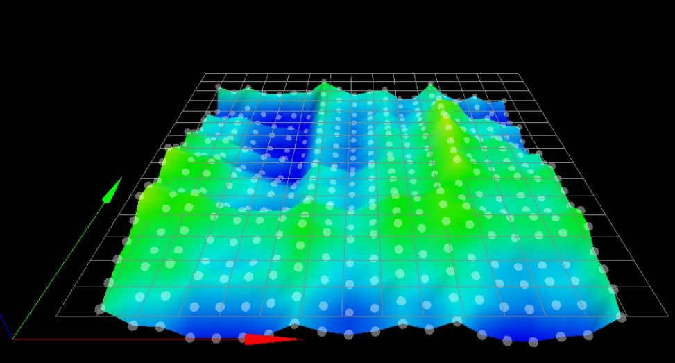
it's a 400 point mesh
; Configuration file for Duet WiFi (firmware version 3)
; executed by the firmware on start-up
;
; generated by RepRapFirmware Configuration Tool v3.2.3 on Thu Jun 24 2021 09:31:20 GMT-0600 (Central Standard Time)

; General preferences
G90                                                      ; send absolute coordinates...
M83                                                      ; ...but relative extruder moves
M550 P"modix_big_meter"                                  ; set printer name

; Network
M552 P0.0.0.0 S1                                         ; enable network and acquire dynamic address via DHCP
M586 P0 S1                                               ; enable HTTP
M586 P1 S0                                               ; disable FTP
M586 P2 S0                                               ; disable Telnet

; Drives
M569 P0 S0                                               ; physical drive 0	X1				reverse
M569 P1 S1                                               ; physical drive 1	X2				forward
M569 P2 R-1                                              ; Physical drive 2	not used
M569 P3 S1                                               ; physical drive 3	E0				forward
M569 P4 S0                                               ; physical drive 4	E1				reverse
; additional drives on duex5 expansion board
M569 P5 S0                                               ; Physical drive 5	Y				reverse
M569 P6 S0                                               ; Physical drive 6	Z1 (0,1000)		reverse
M569 P7 S0                                               ; Physical drive 7	Z2 (0,0) 		reverse
M569 P8 S0                                               ; Physical drive 8	Z3 (1000,0)		reverse
M569 P9 S0                                               ; Physical drive 9	Z4 (1000,1000)	reverse


;M584 X0 Y1 Z7 E3:4                                      ; set drive mapping
M584 X0:1 Y5 Z6:7:8:9 U1 E3:4 P3						 ; map motors to axis
M671 X-181:-181:1049:1049 Y1066:-58:-58:1066 S10	  	 ; CCW positions of Z motors

;~ M350 X16 Y16 Z16 E16:16 I1                            ; configure microstepping with interpolation
;~ M92 X100.00 Y100.00 Z2000.00 E412.00:412.00           ; set steps per mm
;~ M566 X240.00 Y360.00 Z30.00 E120.00:120.00            ; set maximum instantaneous speed changes (mm/min)
;~ M203 X9000.00 Y9000.00 Z199.80 E1200.00:1200.00       ; set maximum speeds (mm/min)
;~ M201 X1000.00 Y1000.00 Z120.00 E250.00:250.00         ; set accelerations (mm/s^2)
;~ M906 X1800 Y1800 Z1800 E1000:1000 I30                 ; set motor currents (mA) and motor idle factor in per cent
;~ M84 S30                                               ; Set idle timeout

M350 X16 Y16 Z16 E16 U16 I1								 ; Configure microstepping with interpolation
M92 X100.00 Y100.00 Z2000.00 E412.32 U100.00			 ; Set steps per mm
M566 X240 Y360 Z30.00 E120.00 U240 P1					 ; Set maximum instantaneous speed changes (mm/min)
M203 X9000.00 Y9000.00 Z200.00 E1200.00 U9000.00		 ; Set maximum speeds (mm/min)
M201 X1000 Y1000 Z120.00 E250.00 U1000					 ; Set accelerations (mm/s^2)
M204 P500 T1000											 ; Set print and travel accelerations  (mm/s^2)
M906 X1800 Y1800.00 E1000.00 U1800 I30 					 ; Set motor currents (mA) and motor idle factor in per cent
M906 Z1800.00 I50 										 ; Set motor currents (mA) and motor idle factor in per cent
M84 S60 X Y U E0 E1										 ; Set idle timeout - one minute

; Axis Limits
M208 X0 Y0 Z0 U0 S1										 ; set axis minima
M208 X1000 Y1000 Z1000 U1000 S0						     ; set axis maxima

; Endstops
;~ M574 X1 S1 P"xstop"                                   ; configure active-high endstop for low end on X via pin xstop
;~ M574 Y2 S1 P"ystop"                                   ; configure active-high endstop for high end on Y via pin ystop
; X1 = X end stop low end
; Y2 = Y end stop high end
; U1 = U end stop low end (U is second X)
; S1 = all active high
; M574 X1 Y2 U1 S1										 ; Set active low and disabled endstops
; Z end stop is actually a probe, high limit
; M574 Z2 S2
M574 X1 S1 P"xstop"
M574 Y2 S1 P"ystop"
M574 U1 S1 P"e0stop"
; Z-Probe

M950 S0 C"duex.e6heat"                                  ; create servo pin 0 for BLTouch
;~ M558 P9 C"^zprobe.in" H5 F120 T6000                  ; set Z probe type to bltouch and the dive height + speeds
M558 P9 C"^zprobe.in" H5 F120 T9000 R0.7                ; set Z probe type to bltouch and the dive height + speeds
;~ G31 P500 X-14 Y21 Z1.081                             ; set Z probe trigger value, offset and trigger height
;~ M557 X0:974 Y21:1000 S52                             ; define mesh grid

                                                     	; Set endstops controlled by probe
; heater 7 output used for PWM of BL touch (e6 heat)
;~ M307 H7 A-1 C-1 D-1                                  ; Disable heater on PWM channel for BLTouch
;~ M558 P9 H5 F120 T9000 A1 R0.7            			; Set Z probe type to bltouch and the dive height + speeds
G31 P500 X-14 Y21 Z1.000                    		    ; Set Z probe trigger value, offset and trigger height(Z-offset)
;M557 X-14:974 Y21:1009 S52 		                    ; Define mesh grid. 400 Points - no longer works with v3, no offset outside of maxima
;
;
                                                        ; Choose one of these mesh methodas and comment out the other
;M557 X30:970 Y30:970 S104 		                        ; Define mesh grid. 100 points
M557 X-14:974 Y21:1009 S52 		                        ; Define mesh grid. 400 Points
;M557 X-15:973 Y22:1008 S34 		                    ; Define mesh grid. 900 Points
;
;
;
M376 H10			                    				; Height (mm) over which to taper off the bed compensation

; Heaters
M140 H-1                                                ; disable heated bed (overrides default heater mapping)
;~ M308 S0 P"e0temp" Y"thermistor" T100000 B4138        ; configure sensor 0 as thermistor on pin e0temp
;~ M950 H0 C"e0heat" T0                                 ; create nozzle heater output on e0heat and map it to sensor 0
;~ M308 S0 P"e0temp" Y"pt1000"
;~ M950 H0 C"e0heat" T0                                 ; create nozzle heater output on e0heat and map it to sensor 0

M308 S0 P"spi.cs1" Y"rtd-max31865" R395 F60
M950 H1 C"e0heat" T0          							; heater 0 uses the e0_heat pin and sensor 1
M307 H1 B0 S1.00                                        ; disable bang-bang mode for heater  and set PWM limit
M143 H1 S285                                            ; set temperature limit for heater 0 to 285C


M308 S1 P"e1temp" Y"thermistor" T100000 B4725 C7.06e-8  ; configure sensor 1 as thermistor on pin e1temp
M950 H2 C"e1heat" T1                                    ; create nozzle heater output on e1heat and map it to sensor 1
M307 H2 B0 S1.00                                        ; disable bang-bang mode for heater  and set PWM limit
M143 H2 S285                                            ; set temperature limit for heater 1 to 285C

; Fans
M950 F0 C"fan0" Q500      ; T0                          ; create fan 0 on pin fan0 and set its frequency
M106 P0 S0 H-1                                          ; set fan 0 value. Thermostatic control is turned off
M950 F1 C"fan1" Q500      ; T1                          ; create fan 1 on pin fan1 and set its frequency
M106 P1 S0 H-1                                          ; set fan 1 value. Thermostatic control is turned off
M950 F2 C"fan2" Q500                                    ; create fan 2 on pin fan2 and set its frequency
M106 P2 S0 H-1                                          ; set fan 2 value. Thermostatic control is turned off
M950 F3 C"duex.fan3" Q500                               ; create fan 3 on pin duex.fan3 and set its frequency
M106 P3 I-1                                             ; set fan 3 value. Thermostatic control is turned off
M950 F4 C"duex.fan4" Q500                               ; create fan 4 on pin duex.fan4 and set its frequency
M106 P4 I-1                                             ; set fan 4 value. Thermostatic control is turned off
M950 F5 C"duex.fan5" Q500                               ; create fan 5 on pin duex.fan5 and set its frequency
M106 P5 S1 H0 T46                                       ; extruder 0           ; set fan 5 value. Thermostatic control is turned on
M950 F6 C"duex.fan6" Q500                               ; create fan 6 on pin duex.fan6 and set its frequency
M106 P6 S1 H1 T46                                       ; extruder 1           ; set fan 6 value. Thermostatic control is turned on
; apparently these disabled defines still seize the IO; don't define so we can use for LED later
;M950 F7 C"duex.fan7" Q500                              ; create fan 7 on pin duex.fan7 and set its frequency
;M106 P7 I-1                                            ; set fan 7 value. Thermostatic control is turned off
M950 F8 C"duex.fan8" Q500                               ; create fan 8 on pin duex.fan8 and set its frequency
M106 P8 I-1                                             ; set fan 8 value. Thermostatic control is turned off

; Tools
M563 P0 S"E0 Primary" D0 H1 F0                          ; define tool 0, E0 drive, heater 1, fan 0
G10 P0 X0 Y0 Z0                                         ; set tool 0 axis offsets
G10 P0 R0 S0                                            ; set initial tool 0 active and standby temperatures to 0C
M563 P1 S"E1 SEcondary" D1 H2 F1                        ; define tool 1
G10 P1 X-0.2 Y52.5 Z0                                   ; set tool 1 axis offsets
G10 P1 R0 S0                                            ; set initial tool 1 active and standby temperatures to 0C

; Custom settings are not defined

; Miscellaneous
M575 P1 S1 B57600                                       ; enable support for PanelDue
M501                                                    ; load saved parameters from non-volatile memory


; Automatic power saving____________________________________________
M911 S22.5 R29.0 P"M913 X0 Y0 G91 M83 G1 Z3 E-5 F1000"   ; Set voltage thresholds and actions to run on power loss. Power Failure Pause

; Custom settings___________________________________________________
;M591 D0:1 P1 C4 S1		   			       	    		 ; Regular filament sensor for E0 and E1
; disabled, fixme


; _______________GPIOs____________________
; LED strip on GPIO 'P1', duex fan7 output
M950 P1 C"duex.fan7" Q500
I just had to rewrite config.g to allow the new firmware, maybe I missed some things. That call to deploy probe might be redundant (I think deployprobe.g and should be called automatically?) Initially I was having conflicts with the probe pin output and a GPIO for LEDs conflicting, since it seems the probe pin is treated as a GPIO as well and they can't both be logical 'P0'. It is a bl-touch probe. Making the LED GPIO 'P1' resolved that, anyway. It's a 400 point map currently. Mechanical adjustment of the bed could be somewhat better.
these macros aren't my creation so I'm not positive
tilt macro
M42 P0 S1 					                            ; Main LED on
G90                                                     ;Absolute Positioning
G10 P0 S0
G10 P1 S0
if !move.axes[0].homed || !move.axes[1].homed	        ; If the printer hasn't been homed, home it
	G28 XY	                                            ; home y and x
;
G28 Z			                                        ; home z
;
M561	                                                ; clear any bed transform
echo "Starting Bed Tilt Calibration"
M98 P"bed_screws.g"		                                ; perform bed tramming
echo "BTC: 1 - Difference was " ^ move.calibration.initial.deviation ^ "mm"
;
;
                                                        ; Select one or the other of the two types of while loops, commenting out the inactive loop
; while move.calibration.initial.deviation >= 0.01		  ; perform additional bed tilt calibrations if previous deviation was over 0.01mm
while iterations < 6		                            ; perform additional based on number of cycles
  echo "Cycle " ^ iterations + 1
  if iterations = 6
    abort "Too many tilt calibration attempts"
  ;                                                      ; the following moveds the bed up and down before each calibration cycle to test if the bed z-steppers are slipping
  ;G91                                                   ; relative Positioning
  ;G1 Z100 F200                                          ; move bed down 100mm
  ;G1 Z-100 F200                                         ; move bed up 100mm
  ;G90                                                   ; absolute Positioning
  ;                                                      ; end stepper slip moves
  M98 P"bed_screws.g"		                            ; perform bed tilt calibration
  echo "BTC: " ^ iterations + 2 ^ " - Difference was " ^ move.calibration.initial.deviation ^ "mm"
  continue
;
G28 Z
echo "Bed Tilt Calibration complete"
mesh probing macro
M561
G28			                                                          ; home all
M561                                                                  ; clear any bed transform
M42 P0 S1 					                                          ; Main LED on
M98 P"0:/macros/Calibration/03_Automatic_Bed_Tilt_Calibration_ABTC"   ; perform bed tilt calculations
M400
;
; Mesh Grid Defined in config.g
;
G28			                                                          ; home all
M561						                                          ; clear any bed transform
echo "Performing Bed Mesh Compensation Mapping"
G29 S0  					                                          ; probe the bed and enable compensation
G4 P999
G28 						                                          ; home all
echo "Bed Mesh Compensation Mapping complete"
M291 S2 P"The bed plate is calibrated and the 400 point heightmap is loaded"
Do you think there will be large error from doing G30 at home (~0,1000) instead of the middle of the bed?
-
@marp said in Verifying mesh levelling:
M376 H10
You may want to disable the taper off as a test. 10mm isn't a lot and it will reduce the amount of compensation being applied.
-
> @marp
>
> With the recent firmware the **G29** command calls **mesh.g** if it exists. All of the commands for creating the height map should be there.
>
> The **G32** command calls **bed.g**. All of the commands for leveling the bed should be there.
>
> A single **G30** to probe the center of the bed and set the **Z=0 datum** should always be called:
> - after leveling the bed
> - before creating a height map
> - before loading a height map
>
> I have code in **mesh.g** and **bed.g** that insures that happens.
>
> Frederick
Can you share your bed.g and mesh.g
-
see https://forum.duet3d.com/topic/23848/automatic-bed-tilt-calibration-g30-s4-and-g30-s-2/44 for a rel;ated converastion prior to this one
-
The equivalent of the bed.g is the macro "0:/macros/Calibration/03_Automatic_Bed_Tilt_Calibration_ABTC" running:
M42 P0 S1 					                            ; Main LED on
G90                                                     ;Absolute Positioning
G10 P0 S0
G10 P1 S0
if !move.axes[0].homed || !move.axes[1].homed	        ; If the printer hasn't been homed, home it
	G28 XY	                                            ; home y and x
;
G28 Z			                                        ; home z
;
M561	                                                ; clear any bed transform
echo "Starting Bed Tilt Calibration"
M98 P"bed_screws.g"		                                ; perform bed tramming
echo "BTC: 1 - Difference was " ^ move.calibration.initial.deviation ^ "mm"
;
;
                                                        ; Select one or the other of the two types of while loops, commenting out the inactive loop
; while move.calibration.initial.deviation >= 0.01		  ; perform additional bed tilt calibrations if previous deviation was over 0.01mm
while iterations < 6		                            ; perform additional based on number of cycles
  echo "Cycle " ^ iterations + 1
  if iterations = 6
    abort "Too many tilt calibration attempts"
  ;                                                      ; the following moveds the bed up and down before each calibration cycle to test if the bed z-steppers are slipping
  ;G91                                                   ; relative Positioning
  ;G1 Z100 F200                                          ; move bed down 100mm
  ;G1 Z-100 F200                                         ; move bed up 100mm
  ;G90                                                   ; absolute Positioning
  ;                                                      ; end stepper slip moves
  M98 P"bed_screws.g"		                            ; perform bed tilt calibration
  echo "BTC: " ^ iterations + 2 ^ " - Difference was " ^ move.calibration.initial.deviation ^ "mm"
  continue
;
G28 Z
echo "Bed Tilt Calibration complete"
The equivalent of mesh.g is the macro "0:/macros/Calibration/04_ABTC + Bed Compensation" with in turn runs the above macro:
M561
G28			                                                          ; home all
M561                                                                  ; clear any bed transform
M42 P0 S1 					                                          ; Main LED on
M98 P"0:/macros/Calibration/03_Automatic_Bed_Tilt_Calibration_ABTC"   ; perform bed tilt calculations
M400
;
; Mesh Grid Defined in config.g
;
G28			                                                          ; home all
M561						                                          ; clear any bed transform
echo "Performing Bed Mesh Compensation Mapping"
G29 S0  					                                          ; probe the bed and enable compensation
G4 P999
G28 						                                          ; home all
echo "Bed Mesh Compensation Mapping complete"
M291 S2 P"The bed plate is calibrated and the 400 point heightmap is loaded"
The "0:/sys/bed_screws.g" macro is called as part of the tilt cal above:
; bed_screws.g
G30 P0 X10 Y10 Z-99999 ; Probe near a leadscrew
G30 P1 X980 Y10 Z-99999 ; Probe near a leadscrew
G30 P2 X980 Y980 Z-99999 ; Probe near a leadscrew
G30 P3 X10 Y980 Z-99999 S4 ; Probe near a leadscrew
These can easily be cleaned up into separate bed.g and mesh.g macros calling with the G32 and G29.
But the concern is that we are unsure that the mesh bed compensation is being taken into account correctly.
-
@phaedrux said in Verifying mesh levelling:
@marp said in Verifying mesh levelling:
M376 H10
You may want to disable the taper off as a test. 10mm isn't a lot and it will reduce the amount of compensation being applied.
You think the 10mm of taper could be causing the issue in it nor properly applying the bed mesh compensation? Please explain more.
-
@phaedrux said in Verifying mesh levelling:
@marp said in Verifying mesh levelling:
the tilt macro calls bedscrews.g which just checks the four corners with G30 and adjusts it.
This macro is basically taking the place of bed.g and G32.
@marp said in Verifying mesh levelling:
M280 P0 S60 ; deploy probe
What kind of probe are you using? Can you post your config.g as well please?
Before doing the G29 you should do a single G30 near the center of the bed, preferably at the same position that acts as a point in the mesh. That ensures that the Z0 point set by G30 also matches a point in the mesh.
How many points are you using in your mesh? For such a large bed you should be using as many as possible which is up to 441.
How many times are you doing the tilt correction?
What does the heightmap actually look like?
it is a BLTouch
-
@bstump said in Verifying mesh levelling:
Please explain more.
Please read about how the taper works.
https://duet3d.dozuki.com/Wiki/Gcode?revisionid=HEAD#Section_M376_Set_bed_compensation_taper
It reduces the amount of compensation applied over the range of distance given, so that by 10mm above Z0, there is no more compensation applied. At 5mm above Z0, only 50% of the compensation is applied.
-
@phaedrux said in Verifying mesh levelling:
@marp said in Verifying mesh levelling:
the tilt macro calls bedscrews.g which just checks the four corners with G30 and adjusts it.
How many points are you using in your mesh? For such a large bed you should be using as many as possible which is up to 441.
How many times are you doing the tilt correction?
We typically do a 400 point mesh.
The bed tilt calibrations runs up to 6 times to dial in.
-
@bstump said in Verifying mesh levelling:
Frederick
Can you share your bed.g and mesh.g
Both of my files are more complicated then they need to be to perform their basic functions - I have included features primarily of use when getting the printer initially dialed in.
Here is my bed.g - it references a number of .G files to perform needed actions - the names indicate what is done.
M98 P"homeALL_verify.g"

M98 P"probe_config.g"

; --- prepare to level bed ---

; M671: Define positions pf manual bed levelling screws or Z leadscrews

; Xnn:nn:nn... list of between 2 and 4 X coordinates of the leadscrews that drive the Z axis or the bed levelling screws
; Ynn:nn:nn... list of between 2 and 4 Y coordinates of the leadscrews that drive the Z axis or the bed levelling screws
; Snn          maximum correction allowed for each leadscrew in mm (optional, default 1.0)
; Pnnn         pitch of the bed levelling screws (not used when bed levelling using independently-driven leadscrews). Defaults to 0.5mm which is correct for M3 bed levelling screws
; Fnn          fudge factor, default 1.0

M671 X-180:0:180 Y-65:130:-65 S3 ; positions of ball studs

M291 R"Leveling bed" P"Please wait..." T0

; --- level bed leveling ---

while true
  ; run leveling pass

  ; determine where to probe

if {global.g_level_mode} != "4PT"
  ; --- probe near ball studs ---

  G30 P0 X-145 Y-65 Z-99999    ; probe near ball stud #1
  G30 P1 X0    Y100 Z-99999    ; probe near ball stud #2
  G30 P2 X145  Y-65 Z-99999 S3 ; probe near ball stud #3

else
  ; --- probe near bed corners ---

  G30 P0 X-140 Y-90 Z-99999    ; LF
  G30 P1 X-140 Y90  Z-99999    ; LR
  G30 P2 X140  Y90  Z-99999    ; RR
  G30 P2 X140  Y-90 Z-99999 S3 ; RF

  ; check results - exit loop if results are good

  if move.calibration.initial.deviation < 0.02
    break

  ; check pass limit - abort if pass limit reached

  if iterations = 5
    M291 P"Bed Leveling Aborted" R"Pass Limit Reached"
    abort "Bed Leveling Aborted - Pass Limit Reached"

; --- finish up ---

; --- set Z=0 datum which can be affected by leveling ---

M98 P"center_probe.g" ; position for probing
G30                   ; do single probe which sets Z to trigger height of Z probe

M291 R"Bed leveling complete" P"OK" T0
Here is my mesh.g:
if {global.g_map_mode} = "NONE" M291 R"Cannot create height map - Map Mode is set to NONE" P"Cannot continue" S2 T0 abort "Map Mode is set to NONE" M98 P"homeALL_query.g" M98 P"probe_set_z.g" ; set Z=0 datum G32 ; level bed to be safe M208 Y-115:100 ; adjust axis min/max to allow for probe offset if {global.g_map_mode} = "FAST4" M291 R"Creating FAST4 Height Map" P"Please wait..." T0 M557 X-140:140 Y-90:90 P2:2 ; define 4 point mesh for G29 G29 S0 ; do probing G29 S3 P"heightmap_FAST4.csv" ; save file with unique name M291 R"FAST4 Height Map Created" P"OK" T1 elif {global.g_map_mode} = "FAST9" M291 R"Creating FAST9 Height Map" P"Please wait..." T0 M557 X-140:140 Y-90:90 P3:3 ; define 9 point mesh for G29 G29 S0 ; do probing G29 S3 P"heightmap_FAST9.csv" ; save file with unique name M291 R"FAST9 Height Map Created" P"OK" T1 else M291 R"Creating FULL Height Map" P"Please wait..." T0 M557 X-140:140 Y-90:90 P20 ; define FULL mesh for G29 (400 points) G29 S0 ; do probing G29 S3 P"heightmap_FULL.csv" ; save file with unique name M291 R"FULL Height Map Created" P"OK" T1 M208 Y-100:100 ; restore axis min/max to normal G29 S2 ; cancel mesh bed compensation M290 R0 S0 ; cancel baby stepping -
@fcwilt I am wondering if the offset between the probe and the nozzle is correctly compensated for in the bed tilt and mesh compensation. with our duel head extruder the probe sits half way between the tow nozzles in the direction for one axis and the aligned for the other axis . I think the nozzle to probe distance is in the range of 50-75mm. In looking at two side by side probe points in the mesh the probing distance is around 5mm and the difference in mesh height can be 0.1 to 0.16mm. I am thinking our bed adhesion issue may be related to the probe to nozzle distance not being fully adjusted for and the mesh compensation being for a real surface point around 5 mm from where the nozzle is. Depending on where on the bed the nozzle is the adjusted mesh may be up or down from what the mesh says because the mesh is effectively pushed back/front by around 50 mm.
-
If I read the following correctly we say the two nozzles are 52.5mm apart and the probe is X-14 Y21 from the first nozzle. I am having this verified.
; Z-Probe
M950 S0 C"duex.e6heat"                                  ; create servo pin 0 for BLTouch
M558 P9 C"^zprobe.in" H5 F120 T9000 R0.7                ; set Z probe type to bltouch and the dive height + speeds
; heater 7 output used for PWM of BL touch (e6 heat)
G31 P500 X-14 Y21 Z1.000                    		    ; Set Z probe trigger value, offset and trigger height(Z-offset)
M557 X-14:974 Y21:1009 S52 		                        ; Define mesh grid. 400 Points
;M376 H10			                    				; Height (mm) over which to taper off the bed compensation
M376 H0			                    					; compensation taper disabled TEST
; Tools M563 P0 S"E0 Primary" D0 H1 F0 ; define tool 0, E0 drive, heater 1, fan 0 G10 P0 X0 Y0 Z0 ; set tool 0 axis offsets G10 P0 R0 S0 ; set initial tool 0 active and standby temperatures to 0C M563 P1 S"E1 SEcondary" D1 H2 F1 ; define tool 1 G10 P1 X-0.2 Y52.5 Z0 ; set tool 1 axis offsets G10 P1 R0 S0 ; set initial tool 1 active and standby temperatures to 0C -
I think the method to do the offsets is correct, but how can we tell if the mesh compensation take these offsets into account correctly? We are still verifying the numbers.
-
@bstump said in Verifying mesh levelling:
@fcwilt I am wondering if the offset between the probe and the nozzle is correctly compensated for in the bed tilt and mesh compensation
I don't actually understand what you are asking.
Frederick
Printers: a E3D MS/TC setup and a RatRig Hybrid. Using Duet 3 hardware running 3.4.6
-
I've never worked with a multi-tool printer.
And I don't find the documentation of G31 very clear in regards to multi-tool printers.
In the absence of any additional information I would set the offsets of the probe to X=0 Y=0 and offsets of each tool relative to the probe.
Testing would reveal if that actually worked.
Frederick
-
@fcwilt said in Verifying mesh levelling:
In the absence of any additional information I would set the offsets of the probe to X=0 Y=0 and offsets of each tool relative to the probe.
You could do that for testing, but I think the default method is to have tool0 be at x0 y0, and the probe for tool 0 offset from that. Tool1 would then have it's offset defined in relation to tool0.
-
@phaedrux said in Verifying mesh levelling:
@fcwilt said in Verifying mesh levelling:
In the absence of any additional information I would set the offsets of the probe to X=0 Y=0 and offsets of each tool relative to the probe.
You could do that for testing, but I think the default method is to have tool0 be at x0 y0, and the probe for tool 0 offset from that. Tool1 would then have it's offset defined in relation to tool0.
That makes sense but I could not find where that is stated.
There is this in the Gode Dictionary for G31:
1X and Y offsets of the Z probe relative to the print head (i.e. the position when the empty tool is selected) can be specified. This allows you to calculate your probe coordinates based on the geometry of the bed, without having to correct them for Z probe X and Y offset.
but I don't know what it is trying to say.
Frederick
Printers: a E3D MS/TC setup and a RatRig Hybrid. Using Duet 3 hardware running 3.4.6
-
@fcwilt said in Verifying mesh levelling:
I don't actually understand what you are asking.
There is an offset between the probe and the nozzle. Assuming our offsets are correct, how can we verify that the mesh compensation take this offset correctly into account when applying the mesh compensation? Basically the probe mesh is offset in two directions to the primary nozzle.
If it takes the offset correctly into account then I would expect the nozzle to follow the mesh contour almost perfectly (given whatever extrapolation method it uses). However if it does not take the offset into account correctly or at all then the applied mesh would be offset from the nozzle and the nozzle would follow an offset contour.
We have a test spiral that covers the bed twice and he pair of lines is 25mm away from the other pair of lines. We see some spots that are nice and some a bit tight and squished, and others that do not adhere and were not proper layer thickness. This leans me to think the whole mesh is offset.
If we compare side by side points (given the large bed that is not easy to level manually) we see between 0.1 and 0.16mm difference in mesh pint heights. If this translates to the nozzle contour that would be great, but It does not. The first pair of points is beside a seam in the plates (three bead plates with 3 separate pieces of PEI. The second pair of points is along one plate.
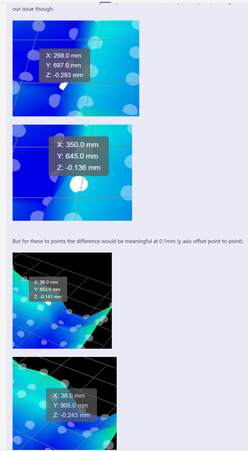
As I said, I am questioning if the probe to nozzle offsets are correctly applied when the bed mesh is applied and questioning how to check that.
-
I've always assumed they are but it's easy to check.
Here is the text of a height map for testing:
RepRapFirmware height map file v2 generated at 2021-01-01 00:00, min error 0.000, max error 0.00, mean 0.000, deviation 0.000
xmin,xmax,ymin,ymax,radius,xspacing,yspacing,xnum,ynum
0.00,150.00,0.00,150.00,-1.00,15.00,150.00,11,2
0, 1, 2, 3, 4, 5, 6, 7, 8, 9, 10
0, 1, 2, 3, 4, 5, 6, 7, 8, 9, 10It greatly exaggerates Z errors so you can jog along the X axis and verify the Z adjustments.
Adjust these values as needed to match your printer:
xmin, xmax, ymin, ymax, radius, xspacing, yspacing, xnum, ynum
Create a file heightmap.csv in your system folder with the data above adjusted for your printer.
Enable mesh compensation using this file.
Frederick
-
@fcwilt said in Verifying mesh levelling:
That makes sense but I could not find where that is stated.
I think it's just convention, since you can set whatever you want as the origin and offset anything from anywhere if you want. It really depends on the setup what makes the most sense.
@fcwilt said in Verifying mesh levelling:
1X and Y offsets of the Z probe relative to the print head (i.e. the position when the empty tool is selected) can be specified. This allows you to calculate your probe coordinates based on the geometry of the bed, without having to correct them for Z probe X and Y offset.
but I don't know what it is trying to say.I think it might be talking about tool changer situations where you may have a probe attached to the head itself rather than a tool. I think the E3D tool changer is an example of that. There is a switch on the carriage itself that is used to probe. The tools are all offset from that.