Triple Z Ballscrew G32 Leveling Wrong Direction
-
So the triple Z leveling seems to act a bit wonky. When the build plate is angled towards the front of the printer (video angle is from the left side) and I run a G32 command it ends up angling more. (Video)
It levels well left to right (looking at front of the printer). So I am a bit confused.
Hopefully, it is something simple I am missing.
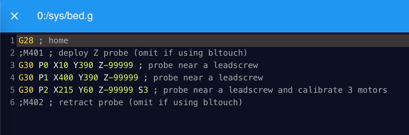
Attached are the Config.g and bed.g screenshots of what I have.

-
Your M584 has this: M584 X0 Y1 Z3:4:5 E4.
Let's assume that is correct - for now.
Then in the M671 the first X/Y values must refer to Z3.
Likewise the second X/Y values must refer to Z4 and the third X/Y values must refer to Z5.
And, of course, each stepper in Z3:4:5 must actually be connected to the stepper that is near those X/Y values.
And the G30 X/Y values in bed.g don't really seem to match up well with the values in M671.
If things are not in sync the process can make the bed less level.
Now back to your M584:
You have Z4 and E4 - one of them must be wrong.
Frederick
Printers: a E3D MS/TC setup and a RatRig Hybrid. Using Duet 3 hardware running 3.4.6
-
@fcwilt Ok I will work on changing/verifying those things.
On a bit of a side note, how do you "switch" can axis?
Right now my X minimum is on my left side, and my Y maximum is at the very front of the printer, Y minimum is at the back. See picture.

How can I switch my Y-Axis direction to be Y0 at the front?
Thanks.
- Jordan
-
@jordan_miller41 can you share your entire config.g file?
Where are your endstops located?
-
@jordan_miller41 said in Triple Z Ballscrew G32 Leveling Wrong Direction:
How can I switch my Y-Axis direction to be Y0 at the front?
M208 X0:100 Y0:100 Z0:100 ; a imaginary printer X=0 to 100 Y=0 to 100 Z=0 to 100

M574 Y1 S1 P"ystop"       ; this would configure an active-high endstop for low end of Y

M574 Y2 S1 P"ystop"       ; this would configure an active-high endstop for high end of Y
The following command would move in the positive direction on Y until it moved 199 mm or the endstop is triggered.
G91
G1 H1 Y199The following command would move in the negative direction on Y until it moved 199 mm or the endstop is triggered
G91
G1 H1 Y-199In either case when the endstop is triggered the Y position is set to according to the settings in M208 and M574
If the M574 specifies the endstop is at the low end of Y then the Y position is set to Y min as specified in M208.
If the M574 specifies the endstop is at the high end of Y then the Y position is set to Y max as specified in M208.
These settings much be "in sync". Things are not going to work as expected if:
-
the endstop is located near Y max but the M574 says it is at Y min.
-
the endstop is located near Y min but the M574 says it is at Y max.
Also the endstop may not actually trigger at exactly Y min or Y max but the Y position is set by the G1 H1 command as if it is.
When this is the case you can use a G1 and/or G92 commands to get the actual Y position to match the firmware Y position.
My guess is you have got M208 and/or M574 wrong.
Of course you have to have the M569 command set so the axis moves in the proper direction for + or - moves.
Printers: a E3D MS/TC setup and a RatRig Hybrid. Using Duet 3 hardware running 3.4.6
-
-
It gets a little more complicated with coreXY. When in doubt, use this motor direction test.
https://duet3d.dozuki.com/Wiki/ConfiguringRepRapFirmwareCoreXYPrinter#Section_Testing_motor_movement
-
@nuramori said in Triple Z Ballscrew G32 Leveling Wrong Direction:
@jordan_miller41 can you share your entire config.g file?
Where are your endstops located?
End stops are located left side for X and Front Left for Y. I do remember having the Y setup to where the homing is at the maximum and I think it was because it went the wrong way initially, I could be remembering wrong as this was 6+ months ago when I first started.
@fcwilt
Here is my current config.g:; Configuration file for Duet 3 (firmware version 3)
; executed by the firmware on start-up
;
; generated by RepRapFirmware Configuration Tool v3.2.3 on Sat Jul 10 2021 12:06:00 GMT-0400 (EDT); General preferences
G90 ; send absolute coordinates...
M83 ; ...but relative extruder moves
M550 P"Duet 3" ; set printer name
M669 K1 ; select CoreXY mode; Drives
M569 P0.0 S1 ; physical drive 0.0 goes forwards
M569 P0.1 S1 ; physical drive 0.1 goes forwards
M569 P0.2 S0 ; physical drive 0.2 goes forwards
M569 P0.3 S1 ; physical drive 0.3 goes forwards
M569 P0.4 S1 ; physical drive 0.4 goes forwards
M584 X0.0 Y0.1 Z0.2 C0.2 E0.3:0.4 ; set drive mapping
M350 X16 Y16 Z16 C16 E16:16 I1 ; configure microstepping with interpolation
M350 C16 I10 ; Configure microstepping without interpolation (toolchange motor)
M92 X80.00 Y80.00 Z800.00 C91.022 E145.51:145.51 ; set steps per mm
M566 X400.00 Y400.00 Z60.00 C2 E120.00:120.00 ; set maximum instantaneous speed changes (mm/min)
M203 X20000 Y20000 Z4000 C8000 E1200.00:1200.00 ; set maximum speeds (mm/min)
M201 X2000.00 Y2000.00 Z750.00 C500 E250.00:250.00 ; set accelerations (mm/s^2)
M906 X800 Y800 Z800 C600 E800:800 I30 ; set motor currents (mA) and motor idle factor in per cent
M84 S30 ; Set idle timeout; Axis Limits
M208 X0 Y0 Z0 C-45 S1 ; set axis minima
M208 X400 Y400 Z440 C360 S0 ; set axis maxima; Endstops
M574 X1 S1 P"io1.in" ; configure active-high endstop for low end on X via pin io1.in
M574 Y2 S1 P"io0.in" ; configure active-high endstop for high end on Y via pin io0.in
M574 Z1 S2 ; configure Z-probe endstop for low end on Z
M574 C0 ; no C endstop; Z-Probe
M558 P5 C"^io3.in" H15 F1200 T60000 ; set Z probe type to switch and the dive height + speeds
G31 P500 X0 Y0 Z2.5 ; set Z probe trigger value, offset and trigger height
M557 X15:400 Y50:400 S50 ; define mesh grid; Heaters
M308 S0 P"temp3" Y"thermistor" T100000 B3950 ; configure sensor 0 as thermistor on pin temp3
M950 H0 C"out3" T0 ; create bed heater output on out3 and map it to sensor 0
M307 H0 B0 S1.00 ; disable bang-bang mode for the bed heater and set PWM limit
M140 H0 ; map heated bed to heater 0
M143 H0 S120 ; set temperature limit for heater 0 to 120C
M308 S1 P"temp0" Y"thermistor" T500000 B4723 C1.19622e-7 ; configure sensor 1 as thermistor on pin temp0
M950 H1 C"out1" T1 ; create nozzle heater output on out1 and map it to sensor 1
M307 H1 B0 S1.00 ; disable bang-bang mode for heater and set PWM limit
M143 H1 S455 ; set temperature limit for heater 1 to 455C
M308 S2 P"temp1" Y"thermistor" T100000 B4725 C7.06e-8 ; configure sensor 2 as thermistor on pin temp1
M950 H2 C"out2" T2 ; create nozzle heater output on out2 and map it to sensor 2
M307 H2 B0 S1.00 ; disable bang-bang mode for heater and set PWM limit
M143 H2 S280 ; set temperature limit for heater 2 to 280C
M308 S3 P"1.temp1" Y"thermistor" T10000 B1504 ; configure sensor 3 as thermistor on pin 1.temp1
M950 H3 C"1.out0" T3 ; create chamber heater output on 1.out0 and map it to sensor 3
M307 H3 B0 S1.00 ; disable bang-bang mode for the chamber heater and set PWM limit
M141 H3 ; map chamber to heater 3
M143 H3 S90 ; set temperature limit for heater 3 to 90C; Fans
M950 F0 C"!out4" Q25000 ; create fan 0 on pin !out4 and set its frequency
M106 P0 C"FRONT PANEL" S1 H-1 ; set fan 0 name and value. Thermostatic control is turned off
M950 F1 C"!out5" Q25000 ; create fan 1 on pin !out5 and set its frequency
M106 P1 C"RAD 1 (TOP)" S1 H1 T45 ; set fan 1 name and value. Thermostatic control is turned on
M950 F2 C"!out6" Q25000 ; create fan 2 on pin !out6 and set its frequency
M106 P2 C"RAD 2 (BOTTOM)" S1 H1 T45 ; set fan 2 name and value. Thermostatic control is turned on
M950 F3 C"1.out6" Q500 ; create fan 3 on pin 1.out6 and set its frequency
M106 P3 C"Water Pump" S1 H-1 ; set fan 3 name and value. Thermostatic control is turned off
M950 F4 C"out7" Q500 ; create fan 4 on pin out7 and set its frequency
M106 P4 C"E3D V6 Hotend" S0.5 H2 T45 ; set fan 4 name and value. Thermostatic control is turned on; Tools
M563 P0 S"Mosquito Liquid" D0 H1 F-1 ; define tool 0
G10 P0 X0 Y0 Z0 ; set tool 0 axis offsets
G10 P0 R0 S0 ; set initial tool 0 active and standby temperatures to 0C
M563 P1 S"E3D V6" D1 H2 F-1 ; define tool 1
G10 P1 X0 Y0 Z0 ; set tool 1 axis offsets
G10 P1 R0 S0 ; set initial tool 1 active and standby temperatures to 0C; Custom settings
M584 X0 Y1 Z3:4:5 E4 ; three Z motors connected to driver outputs 2, 5 and 6
M671 X-25.298:200.199:427.12 Y2.021:430.231:20.21 S10 ; ball screws at front left, back middle and front rightM308 S10 P"temp2" Y"thermistor" T10000 B3988 A"Coolant Cold" ; Configure coolant sensor cold side
M308 S11 P"1.temp2" Y"thermistor" T10000 B3988 A"Coolant Hot" ; Configure coolant sensor hot side on toolboard 1 temp2; Miscellaneous
M501 ; load saved parameters from non-volatile memory
M911 S10 R11 P"M913 X0 Y0 G91 M83 G1 Z3 E-5 F1000" ; set voltage thresholds and actions to run on power lossThank you for your help, I will start to implement your suggestions here in an hour or so.
-
@fcwilt Ok.... I followed @Phaedrux 's article he tagged and have my motors flipped, when I move with the G92 command I get my proper +Y to the back of the printer and +X to the right of the printer. Origin being at the front left corner of the build plate.
The next issue I had to deal with was flipping my pins for X&Y endstops, I have X working as it should, but no matter what I change, the Y-axis goes to the back of the printer (Ymax) and not to the front. I changed the M574 Y1 S1 and it still wants to move to the Ymax. So I am kind of at a loss here. Not sure what is happening, I am sure it is something simple I am missing.
Updated config.g:
; Configuration file for Duet 3 (firmware version 3)
; executed by the firmware on start-up
;
; generated by RepRapFirmware Configuration Tool v3.2.3 on Sat Jul 10 2021 12:06:00 GMT-0400 (EDT); General preferences
G90 ; send absolute coordinates...
M83 ; ...but relative extruder moves
M550 P"Duet 3" ; set printer name
M669 K1 ; select CoreXY mode; Drives
M569 P0.0 S1 ; physical drive 0.0 goes forwards
M569 P0.1 S1 ; physical drive 0.1 goes forwards
M569 P0.2 S0 ; physical drive 0.2 goes forwards
M569 P0.3 S1 ; physical drive 0.3 goes forwards
M569 P0.4 S1 ; physical drive 0.4 goes forwards
M584 X0.0 Y0.1 Z0.2 C0.2 E0.3:0.4 ; set drive mapping
M350 X16 Y16 Z16 C16 E16:16 I1 ; configure microstepping with interpolation
M350 C16 I10 ; Configure microstepping without interpolation (toolchange motor)
M92 X80.00 Y80.00 Z800.00 C91.022 E145.51:145.51 ; set steps per mm
M566 X400.00 Y400.00 Z60.00 C2 E120.00:120.00 ; set maximum instantaneous speed changes (mm/min)
M203 X20000 Y20000 Z4000 C8000 E1200.00:1200.00 ; set maximum speeds (mm/min)
M201 X2000.00 Y2000.00 Z750.00 C500 E250.00:250.00 ; set accelerations (mm/s^2)
M906 X800 Y800 Z800 C600 E800:800 I30 ; set motor currents (mA) and motor idle factor in per cent
M84 S30 ; Set idle timeout; Axis Limits
M208 X0 Y0 Z0 C-45 S1 ; set axis minima
M208 X400 Y400 Z440 C360 S0 ; set axis maxima; Endstops
M574 X1 S1 P"io1.in" ; configure active-high endstop for high end on X via pin io1.in
M574 Y1 S1 P"io0.in" ; configure active-high endstop for low end on Y via pin io0.in
M574 Z1 S2 ; configure Z-probe endstop for low end on Z
M574 C0 ; no C endstop; Z-Probe
M558 P5 C"^io3.in" H15 F1200 T60000 ; set Z probe type to switch and the dive height + speeds
G31 P500 X0 Y0 Z2.5 ; set Z probe trigger value, offset and trigger height
M557 X15:400 Y50:400 S50 ; define mesh grid; Heaters
M308 S0 P"temp3" Y"thermistor" T100000 B3950 ; configure sensor 0 as thermistor on pin temp3
M950 H0 C"out3" T0 ; create bed heater output on out3 and map it to sensor 0
M307 H0 B0 S1.00 ; disable bang-bang mode for the bed heater and set PWM limit
M140 H0 ; map heated bed to heater 0
M143 H0 S120 ; set temperature limit for heater 0 to 120C
M308 S1 P"temp0" Y"thermistor" T500000 B4723 C1.19622e-7 ; configure sensor 1 as thermistor on pin temp0
M950 H1 C"out1" T1 ; create nozzle heater output on out1 and map it to sensor 1
M307 H1 B0 S1.00 ; disable bang-bang mode for heater and set PWM limit
M143 H1 S455 ; set temperature limit for heater 1 to 455C
M308 S2 P"temp1" Y"thermistor" T100000 B4725 C7.06e-8 ; configure sensor 2 as thermistor on pin temp1
M950 H2 C"out2" T2 ; create nozzle heater output on out2 and map it to sensor 2
M307 H2 B0 S1.00 ; disable bang-bang mode for heater and set PWM limit
M143 H2 S280 ; set temperature limit for heater 2 to 280C
M308 S3 P"1.temp1" Y"thermistor" T10000 B1504 ; configure sensor 3 as thermistor on pin 1.temp1
M950 H3 C"1.out0" T3 ; create chamber heater output on 1.out0 and map it to sensor 3
M307 H3 B0 S1.00 ; disable bang-bang mode for the chamber heater and set PWM limit
M141 H3 ; map chamber to heater 3
M143 H3 S90 ; set temperature limit for heater 3 to 90C; Fans
M950 F0 C"!out4" Q25000 ; create fan 0 on pin !out4 and set its frequency
M106 P0 C"FRONT PANEL" S1 H-1 ; set fan 0 name and value. Thermostatic control is turned off
M950 F1 C"!out5" Q25000 ; create fan 1 on pin !out5 and set its frequency
M106 P1 C"RAD 1 (TOP)" S1 H1 T45 ; set fan 1 name and value. Thermostatic control is turned on
M950 F2 C"!out6" Q25000 ; create fan 2 on pin !out6 and set its frequency
M106 P2 C"RAD 2 (BOTTOM)" S1 H1 T45 ; set fan 2 name and value. Thermostatic control is turned on
M950 F3 C"1.out6" Q500 ; create fan 3 on pin 1.out6 and set its frequency
M106 P3 C"Water Pump" S1 H-1 ; set fan 3 name and value. Thermostatic control is turned off
M950 F4 C"out7" Q500 ; create fan 4 on pin out7 and set its frequency
M106 P4 C"E3D V6 Hotend" S0.5 H2 T45 ; set fan 4 name and value. Thermostatic control is turned on; Tools
M563 P0 S"Mosquito Liquid" D0 H1 F-1 ; define tool 0
G10 P0 X0 Y0 Z0 ; set tool 0 axis offsets
G10 P0 R0 S0 ; set initial tool 0 active and standby temperatures to 0C
M563 P1 S"E3D V6" D1 H2 F-1 ; define tool 1
G10 P1 X0 Y0 Z0 ; set tool 1 axis offsets
G10 P1 R0 S0 ; set initial tool 1 active and standby temperatures to 0C; Custom settings
M584 X0 Y1 Z3:4:5 E4 ; three Z motors connected to driver outputs 2, 5 and 6
M671 X-25.298:200.199:427.12 Y2.021:430.231:20.21 S10 ; ball screws at front left, back middle and front rightM308 S10 P"temp2" Y"thermistor" T10000 B3988 A"Coolant Cold" ; Configure coolant sensor cold side
M308 S11 P"1.temp2" Y"thermistor" T10000 B3988 A"Coolant Hot" ; Configure coolant sensor hot side on toolboard 1 temp2; Miscellaneous
M501 ; load saved parameters from non-volatile memory
M911 S10 R11 P"M913 X0 Y0 G91 M83 G1 Z3 E-5 F1000" ; set voltage thresholds and actions to run on power loss -
@jordan_miller41 the config.g just tells the machine where the endstops are. You want to edit the homing files (homey.g and homell.g in your case) to change what it does when you click the home buttons
-
@engikeneer that would make sense now wouldn't it. Thank you for pointing out my blindspot.
-
@fcwilt @engikeneer @Nuramori works great now and levels great, thank you, stuff was massively screwed up. Thank you for your help I appreciate it.
- Jordan
-
@fcwilt said in Triple Z Ballscrew G32 Leveling Wrong Direction:
Your M584 has this: M584 X0 Y1 Z3:4:5 E4.
Let's assume that is correct - for now.
Then in the M671 the first X/Y values must refer to Z3.
Likewise the second X/Y values must refer to Z4 and the third X/Y values must refer to Z5.
And, of course, each stepper in Z3:4:5 must actually be connected to the stepper that is near those X/Y values.
And the G30 X/Y values in bed.g don't really seem to match up well with the values in M671.
If things are not in sync the process can make the bed less level.
Now back to your M584:
You have Z4 and E4 - one of them must be wrong.
Frederick
Can you explain to me what the E4 vs Z4 thing you are talking about is? Is E4 even needed, I am kinda confused.
- Jordan
-
@jordan_miller41 said in Triple Z Ballscrew G32 Leveling Wrong Direction:
@fcwilt @engikeneer @Nuramori works great now and levels great, thank you, stuff was massively screwed up. Thank you for your help I appreciate it.
Always glad to try and help.
We also try to avoid making things worse.
")
Frederick
-
@jordan_miller41 said in Triple Z Ballscrew G32 Leveling Wrong Direction:
Your M584 has this: M584 X0 Y1 Z3:4:5 E4.
Can you explain to me what the E4 vs Z4 thing you are talking about is? Is E4 even needed, I am kinda confused.
Your board has driver connections for 5 steppers.
In your M569 they are P0.0 to P0.4.
Just FYI, since the 0. prefix is the default you can use the short form of P0 to P4.
The first M584 you posted had X0 Y1 Z3:4:5 E4 which says:
X is connected to driver 0
Y is connected to driver 1
Z is connected to drivers 3, 4, 5 (meaning 3 steppers for auto leveling)
E is connected to drive 4.So the Z seemed wrong since you didn't seem to have 6 drivers.
The E seemed wrong since the Z was already specified as using drive 4 so E could not also use drive 4.
Your last M584 has X0.0 Y0.1 Z0.2 C0.2 E0.3:0.4 or in the simplified form X0 Y1 Z2 C2 E3:4
I have no idea what the point of C0.2 is.
The E makes sense if you have two extruders.
So what is C?
And do you have two extruders?
Thanks.
Frederick
-
@fcwilt Ok, that's kind of what I was thinking. Here is my layout. Btw I have Duet 3 6ch MB and Duet 3Ch daughterboard with SBC Raspi 4.
I also am using E3D's toolchanger, therefore the C-Axis.
Mainboard:
Drive 0: X
Drive 1: Y
Drive 2,3,4: Triple Z
Drive 5: C axis (toolchanger)Expansion Board:
1.Drive 0: E0
1.Drive1: E1Does this clear things up? I think we were getting some wires crossed haha.
So would this be correct to correctly map what I have above?
M569 P0.0 S1 ; physical drive 0.0 goes forwards
M569 P0.1 S1 ; physical drive 0.1 goes forwards
M569 P0.2 S0 ; physical drive 0.2 goes forwards
M569 P0.3 S1 ; physical drive 0.3 goes forwards
M569 P0.4 S1 ; physical drive 0.4 goes forwards
M569 P0.5 S1 ; physical drive 0.5 goes forwards
M569 P1.0 S1 ; physical drive 1.0 goes forwards
M569 P1.1 S1 ; physical drive 1.1 goes forwards
M584 X0.0 Y0.1 Z0.2 C0.5 E1.0:1.1 ; set drive mapping -
@jordan_miller41 said in Triple Z Ballscrew G32 Leveling Wrong Direction:
@fcwilt Ok, that's kind of what I was thinking. Here is my layout. Btw I have Duet 3 6ch MB and Duet 3Ch daughterboard with SBC Raspi 4.
I also am using E3D's toolchanger, therefore the C-Axis.
Mainboard:
Drive 0: X
Drive 1: Y
Drive 2,3,4: Triple Z
Drive 5: C axis (toolchanger)Expansion Board:
1.Drive 0: E0
1.Drive1: E1Does this clear things up? I think we were getting some wires crossed haha.
So would this be correct to correctly map what I have above?
M569 P0.0 S1 ; physical drive 0.0 goes forwards
M569 P0.1 S1 ; physical drive 0.1 goes forwards
M569 P0.2 S0 ; physical drive 0.2 goes forwards
M569 P0.3 S1 ; physical drive 0.3 goes forwards
M569 P0.4 S1 ; physical drive 0.4 goes forwards
M569 P0.5 S1 ; physical drive 0.5 goes forwards
M569 P1.0 S1 ; physical drive 1.0 goes forwards
M569 P1.1 S1 ; physical drive 1.1 goes forwards
M584 X0.0 Y0.1 Z0.2 C0.5 E1.0:1.1 ; set drive mappingClose.
M584 X0.0 Y0.1 Z0.2:0.3:0.4 C0.5 E1.0:1.1
-
@jordan_miller41 lol, I didn't add anything - that was all the other guys.