Seeking a source for milling
-
Any competent machinist with a high quality manual mill should be able to achieve .025mm flatness. CNC with flood coolant will usually provide a better overall finish and probably better than .025. Try your local machine shop but plan on an hour or 2 labor for 1 plate
-
I think the challenge is a bit greater than you are all being led on to believe.
The cast tooling plates are already milled flat. The flatness tolerance specification is likely derived from their experience of how much the material can move when it is cut.
The metal has what I have heard referred to as internal stress. When you mill something flat, even if your machine is within 0.001 mm flat, the piece will move when you unclamp it.
How much it moves is a function of how thick the plate is, how much internal stress there is, and in which manner that stress manifests itself as strain (strain being the displacement of material, whereas stress is the force which causes it).
Basically. You won't be able to machine it flat without a lot of trial and error and headache.
I've tried to lap aluminum parts flat. Once you think you have it flat, you measure it along a new axis and realize it has merely warped in the other direction.
-
@bot Regarding stresses in materials - anecdotally, when I started my apprenticeship back in 1969, we had to make some of our own tools. Some items such as slip gauges and parallels had to be made to extremely fine tolerances. The process involved making the parts slightly larger, then they were simply left outside for at least a year before final machining. The reason is that, when metals are formed into ingots or billets from heated or molten materials, stresses are set up as they cool but those stresses are in equilibrium so the ingots or billets maintain their shape. When material is removed, the stresses are no longer in equilibrium, so the part will distort. Heat treatment can sometimes help but the best thing to do is simply to leave the part to buckle and twist (which can take a year or more), then do the final light machining.
The same applies to wood, even if it has been seasoned and is dry. (Woodturning was another of my past hobbies). If you want to make a large fruit or salad bowl, then you have to rough it out oversized, then leave it for 6 months at least to buckle and twist, then do the final light machining.
My final anecdote is related to F1 engines. In the 80s, BMW produced a 1.5 litre turbo engine which produced around 1400 BHP. It was based on their old 1960s M10 engine and one of the reasons for choosing it was that they had a large stock of old blocks which had simply been left outside for years. So all the initial stresses had equalised and they were able to do the final light machining in the knowledge that the new blocks would maintain their very tight tolerances.
How much a part will buckle and twist after machining depends on many factors but as a general rule, the more material is removed, the more the internal stresses become unbalanced so the more it will distort.
-
To say I do it every day would be a bit of an overstatement but I do work within these tolerances regularly. It's my vocation. A primary attribute of the cast tooling plate is its lack of internal or sometimes referred to residual stress with other processing methods. There is machine induced stress from localized heat or cold working but it's unlikely especially when taking skim cuts with the appropriate tooling. If I where to true up a piece like this I would tape it down with double sided tape. The main concern would be what actually happens to it at 100c. Probably loose some of the flatness. I have tried hand lapping too. The problem is a humans cant control downward force ( or the lack there of) accurately enough. A pure lateral force is required.
-
@fcwilt What do you put on top of the aluminum plate for print adhesion? If you're having problems with flatness, maybe it's that surface (or underlying adhesive) that isn't flat enough, or maybe the XY positioning mechanism is sagging, which can make the plate look like it's bowed. Or maybe whatever the plate is mounted on is deforming when the plate is heated- are you using a kinematic mount for the plate?
-
Depending how distorted the plate is to start with, lapping is certainly an option, and inexpensive, if you have access to a sufficiently large known flat surface. The "right way" is to use a granite slab or surface plate, but that's usually not available unless you can "rent" one for a weekend from a shop. That, some sheets of wet/dry sandpaper, water, and a few hours should get you there if it not too far off. It also has the benefit of clearly showing progress as the high points are ground down, and when you're done.
Given the goal though, a variation of the above may be in order. That is, since you support the bed on three points, to make it really flat means that it should be ground when mounted to the same supports. That way, any sagging is accounted for. It also means making a 3-point jig and moving the grinding surface, not the bed.
Zooming out a bit, why is it necessary to reach such perfection for the surface? I understand wanting to make the printer as good as it can be, but at some point, the costs may outweigh the gains. Do you have an estimation of its current distortion? Also, since you're applying a 400-point bed compensation, what does the error end up being then?
-
@kb58 said in Seeking a source for milling:
Zooming out a bit, why is it necessary to reach such perfection for the surface?
Because I am somewhat OC and it is satisfying to have a nice flat bed.
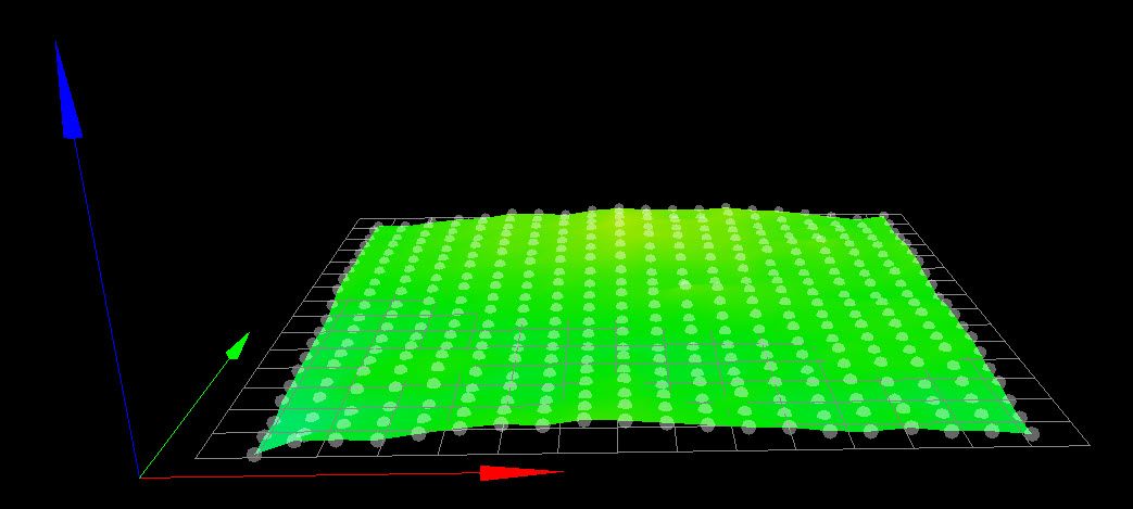
Here is one I am satisfied with:
Here is the one that I am not satisfied with:
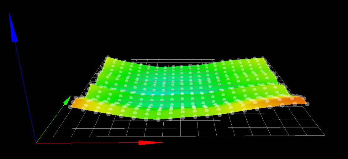
However it's possible that it is a gantry issue but my ability to measure for that is limited.
I'm still working on it.
Frederick
-
@fcwilt said in Seeking a source for milling:
Here is the one that I am not satisfied with:
I print with that one all the time. Nothing a little mesh can't fix.

-
@phaedrux said in Seeking a source for milling:
@fcwilt said in Seeking a source for milling:
Here is the one that I am not satisfied with:
I print with that one all the time. Nothing a little mesh can't fix.
I do understand that - it's just my somewhat OC nature makes it unsatisfying and thus I strive for flatter.
But you must admit that first image is pretty nice.
Frederick
-
@fcwilt, first image is obscene, second image is about as good as you can expect unless you won the bed plate lottery!
Unfortunately, my beds are nowhere near as nice .... but I can dream")
-
@jens55 said in Seeking a source for milling:
@fcwilt, first image is obscene, second image is about as good as you can expect unless you won the bed plate lottery!
You must be using "obscene" in a way I am not familiar with.
")
-
@fcwilt .... probably ..... from Merriam-Webster: so excessive as to be offensive
Or put another way ..... <sigh>, I wish I could come even half way close to that .... or "you dog" .... or just <sigh> -
@fcwilt said in Seeking a source for milling:
... However it's possible that it is a gantry issue but my ability to measure for that is limited.
Frederick <
It can be done with a known flat surface. It needs to be propped up at a level approximating the bed position, then do a profile sweep of that. Any deviations from perfection will be gantry deflection. It'll work even if it's not perfectly level, as the profile map might show a tilt, but it should be straight.