• Tags
  • Documentation
  • Order
  • Register
  • Login
Duet3D Logo Duet3D
  • Tags
  • Documentation
  • Order
  • Register
  • Login

4 endstops for 4 z stepper motor and 3D Touch possible?

Scheduled Pinned Locked Moved
Firmware installation
5
16
639
Loading More Posts
  • Oldest to Newest
  • Newest to Oldest
  • Most Votes
Reply
  • Reply as topic
Log in to reply
This topic has been deleted. Only users with topic management privileges can see it.
  • undefined
    Duncan
    last edited by 2 Aug 2021, 11:49

    Hello,

    I have Duet 3 MB6HC and 4 stepper motors for Z axis connected to the board... I read that it's not possible with Reprapfirmware to have two endstops for one motor (for negative and positive maximum positions)... but is it possible to have one endstop for max positive movement for example in each of them and one 3D Touch for homming Z to negative position and calibrate bed?

    Thanks

    undefined 1 Reply Last reply 2 Aug 2021, 11:53 Reply Quote 0
    • undefined
      chrishamm administrators @Duncan
      last edited by chrishamm 8 Feb 2021, 11:53 2 Aug 2021, 11:53

      @duncan Yes, that should be supported. When you set up the Z endstop , combine the different input ports with + like

      M574 P"^io2.in+^io3.in+^io4.in+^io5.in" Z1 S1
      

      Note that the order of endstops should match the order of configured drivers.

      Duet software engineer

      1 Reply Last reply Reply Quote 0
      • undefined
        Phaedrux Moderator
        last edited by 2 Aug 2021, 17:00

        Multiple endstops in RRF3 as described here: https://duet3d.dozuki.com/Wiki/Bed_levelling_using_multiple_independent_Z_motors#Section_In_RepRapFirmware_Num_3

        Using a probe as well is easy as well. The Endstops are used during G1 H1 homing moves and the probe is used when G30 is called. So you have control over how things are homed in your homing files.

        Z-Bot CoreXY Build | Thingiverse Profile

        1 Reply Last reply Reply Quote 0
        • undefined
          Duncan
          last edited by 6 Aug 2021, 07:44

          @phaedrux @chrishamm

          Thank you for the information, I opened other issue about endstops that I can only get them working on input 1 on the mainboard... because if I can't solve that I can't get this working anyway

          1 Reply Last reply Reply Quote 0
          • undefined
            Duncan
            last edited by 2 Sept 2021, 11:47

            Hello again, endstops are working now... but I have problems with the Z endstops, this is my config.g

            ; Network
            M552 P0.0.0.0 S1                                        ; enable network and acquire dynamic address via DHCP
            M586 P0 S1                                              ; enable HTTP
            M586 P1 S0                                              ; disable FTP
            M586 P2 S0                                              ; disable Telnet
            
            ; Drives
            
            M584 X40.0 Y41.0 Z1:2:4:5 E20.0				; J- configuramos los motores X, Y, Z y E en cada posición de la placa principal o placas externas.
            M671 X1115:1115:-15:-15 Y1360:-260:-260:1360 S0.5	; J- configuramos la posición de los husillos respecto el origen (0,0) de la cama (no de los finales de carrera)
            ;M584 X40.0						; set X driver
            ;M584 Y41.0 					; set Y driver
            ;M584 Z1:2:4:5 					; set Z driver
            ;M584 E20.0						; set E driver
            
            M569 P0 S0                                           ; physical drive 0.0 goes forwards
            M569 P1 S0                                           ; physical drive 0.1 goes forwards
            M569 P2 S0                                           ; physical drive 0.2 goes forwards
            M569 P3 S0                                           ; physical drive 0.3 goes forwards
            M569 P4 S0                                           ; physical drive 0.4 goes forwards
            M569 P5 S0										; physical drive 0.5 goes forwards
            G4 S1 													;wait for expansion boards to start
            M569 P40.0 S1 R0 T2.7										; change enable polarity, active = disable drive
            M569 P41.0 S0 R0 T2.7
            M569 P20.0 S1 
            										
                              				; set drive mapping
            M350 X16 Y16 Z32 E16 I1                           			; configure microstepping with interpolation
            M92 X133.333 Y133.333 Z1280 E420.00	         			; set steps per mm
            M566 X900.00 Y900.00 Z12 E120.00			       		; set maximum instantaneous speed changes (mm/min)
            M203 X6000.00 Y6000.00 Z180 E1200.00					; set maximum speeds (mm/min)
            M201 X500.00 Y500.00 Z100.00 E250.00		    			; set accelerations (mm/s^2)
            M906 X1000 Y1000 Z3000 E800 I30		                    		; set motor currents (mA) and motor idle factor in per cent
            G21 									; TRABAJO EN MM
            G90 									; TRABAJO EN CORDENADAS ABSOLUTAS
            M84 S30                                                 		; Set idle timeout
            
            ; Axis Limits
            M208 X-50 Y-27 Z0 S1                                       		; set axis minima
            M208 X1100 Y1100 Z1000 S0                                  		; set axis maxima
            
            ; Endstops
            M574 X1 S1 P"io0.in"                                ; configure active-high endstop for low end on X via pin io0.in
            M574 Y1 S1 P"io1.in"                                ; configure active-high endstop for low end on Y via pin io1.in
            M574 Z1 S1 P"io3.in+io4.in+io5.in+io6.in" 		    ; configuramos finales de carrera eje Z según orden de motores
            
            ; Z-Probe
            M950 S0 C"20.io0.out"                           ; create servo pin 0 for BLTouch
            M558 P9 C"^20.io0.in" H10 F120 T6000             ; set Z probe type to bltouch and the dive height + speeds
            G31 P500 X20 Y40 Z0                          ; set Z probe trigger value, offset and trigger height
            M557 X50:1100 Y70:1100 S500                     ; define mesh grid
            
            ; Heaters
            ;M308 S0 P"temp0" Y"thermistor" B4725 C7.06e-8            ; configure sensor 0 as thermistor on pin temp0
            ;M950 H0 C"out0" T0                                      ; create bed heater output on out0 and map it to sensor 0
            ;M307 H0 B1 S1.00                                        ; enable bang-bang mode for the bed heater and set PWM limit
            ;M140 H0                                                 ; map heated bed to heater 0
            ;M143 H0 S120                                            ; set temperature limit for heater 0 to 120C
            M308 S0 P"20.temp0" Y"thermistor" B4725 C7.06e-8             ; configure sensor 1 as thermistor on pin temp1
            M950 H1 C"20.out0" T0                                      ; create nozzle heater output on out1 and map it to sensor 1
            M307 H0 B0 S1.00                                        ; disable bang-bang mode for heater  and set PWM limit
            M143 H0 S120                                           ; set temperature limit for heater 0 to 120C
            
            
            ; Fans
            M950 F0 C"20.out1" Q500                                    ; create fan 0 on pin out7 and set its frequency
              
            M106 P0 S255 H0 T50	 
            M106 P0 S0; Herramienta 2 PCF                                      
            
            ; Tools
            M563 P0 D0 H1 F0                                        ; define tool 0
            G10 P0 X0 Y0 Z0                                         ; set tool 0 axis offsets
            ;G10 P0 R0 S0                                            ; set initial tool 0 active and standby temperatures to 0C


            ; Custom settings are not defined
            ;M556 S100 X0 Y0 Z0 ; Put your axis compensation here
            ;M912 P9 S0 ; Put your CPU temperature sensor correction here
            ;M501 ; Run config-override.g
            ;T0 ; Select the first head
            
            ; Miscellaneous
            M575 P1 S1 B57600                                       ; enable support for PanelDue
            M564 H0
            M302 P1
            

            My bed.g

            ; bed.g
            ; called to perform automatic bed compensation via G32
            ;
            ; generated by RepRapFirmware Configuration Tool v3.1.4 on Mon Aug 31 2020 15:45:57 GMT+0800 
            
            ;M561 ; clear any bed transform
            ;G28 XY
            ;G29  ; probe the bed and enable compensation
            
            G28
            G30 P0 X1100 Y1360 Z-99999 		; calibra junto motor (1)
            G30 P1 X1100 Y30 Z-99999		; calibra junto motor (2)
            G30 P2 X20 Y30 Z-99999			; calibra junto motor (4)
            G30 P3 X20 Y1360 Z-99999		; calibra junto motor (5)
            

            and home.z

            ; homez.g
            ; called to home the Z axis
            ;
            ; generated by RepRapFirmware Configuration Tool v3.1.4 on Fri Sep 04 2020 14:49:01 GMT+0800 (中国标准时间)
            G91              ; relative positioning
            G1 H2 Z10 F6000   ; lift Z relative to current position
            ;G1 H2 X510 Y510 F6000 ; go to first probe point
            G1 H1 Z-99999
            G90              ; absolute positioning
            G30              ; home Z by probing the bed - activar 3D Touch
            

            The problem I have now is that I can't see endstops 3, 4, 5 and 6 in Object Model, but io2.in appears to be activated somehow... and always true... so when I try to home z the motor in position 4 is not moving... and I really have no clue why is happening that.
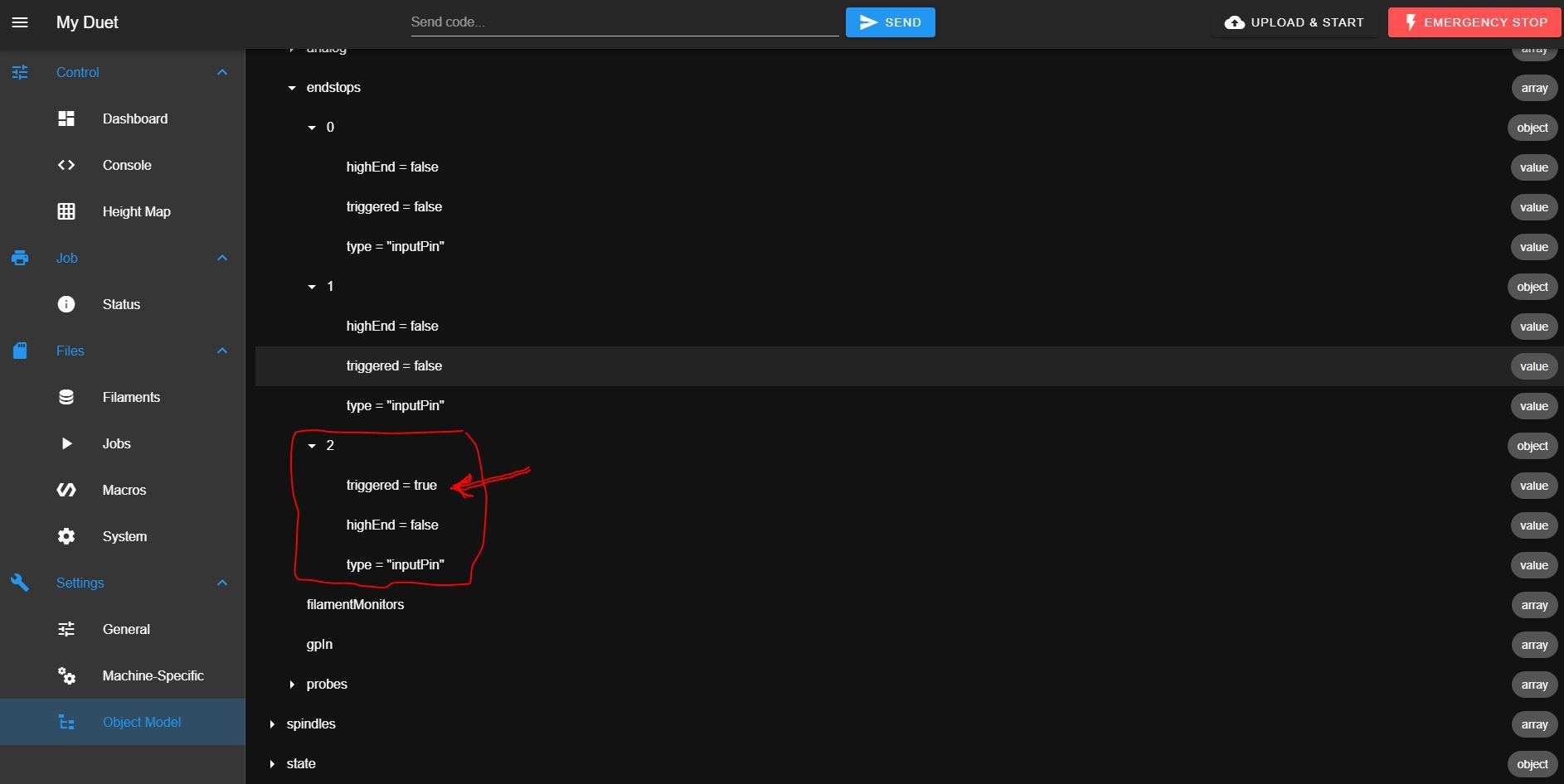
            io2true.JPG

            Any ideas? Thanks!

            1 Reply Last reply Reply Quote 0
            • undefined
              Phaedrux Moderator
              last edited by 2 Sept 2021, 15:31

              Are you perhaps getting some interference with the wiring for that endstop?

              How can you tell that io2.in is always activated?

              Z-Bot CoreXY Build | Thingiverse Profile

              undefined 1 Reply Last reply 3 Sept 2021, 05:37 Reply Quote 0
              • undefined
                Duncan @Phaedrux
                last edited by 3 Sept 2021, 05:37

                @phaedrux because triggered is = true always and I have nothing connected to io2.in or any line in configuration with io2.in...

                That's why I don't understand why appears the 2 port on endstops if I'm setting the Z with io3, io4, io5, and io6 inputs for the 4 stepper motors.

                jay_s_ukundefined 1 Reply Last reply 3 Sept 2021, 05:44 Reply Quote 0
                • jay_s_ukundefined
                  jay_s_uk @Duncan
                  last edited by 3 Sept 2021, 05:44

                  @duncan the number 2 doesn't correspond to IO2, it corresponds to the 3 endstop created for the system (when the numbering starts at 0). In this instance, thats your endstop(s) for z

                  Owns various duet boards and is the main wiki maintainer for the Teamgloomy LPC/STM32 port of RRF. Assume I'm running whatever the latest beta/stable build is

                  undefined 1 Reply Last reply 3 Sept 2021, 06:24 Reply Quote 0
                  • undefined
                    Duncan @jay_s_uk
                    last edited by 3 Sept 2021, 06:24

                    @jay_s_uk but I have 4 endstops defined

                    M574 Z1 S1 P"io3.in+io4.in+io5.in+io6.in"
                    

                    So it's not possible to see the status of each endstop when we use more than one for one axis?

                    Then I think the problem is that the one on io5.in that is the motor number 4

                    M584 X40.0 Y41.0 Z1:2:4:5 E20.0
                    

                    appears to be always triggered...

                    jay_s_ukundefined 1 Reply Last reply 3 Sept 2021, 06:26 Reply Quote 0
                    • jay_s_ukundefined
                      jay_s_uk @Duncan
                      last edited by 3 Sept 2021, 06:26

                      @duncan they are for a global axis though, not 4 individual axes.
                      If you unplug the endstop on IO5 does it no longer show as triggered?
                      Does it then show as triggered when pressing each endstop?
                      If it does show as not triggered when IO5 is connected then I would be investigating the wiring on that endstop

                      Owns various duet boards and is the main wiki maintainer for the Teamgloomy LPC/STM32 port of RRF. Assume I'm running whatever the latest beta/stable build is

                      undefined 1 Reply Last reply 3 Sept 2021, 06:55 Reply Quote 0
                      • undefined
                        Duncan @jay_s_uk
                        last edited by 3 Sept 2021, 06:55

                        @jay_s_uk when I disconnect one endstop from the board is always triggered to true in normal case.

                        I tried disconnecting io5 and remains true, and disconnected all other 3 endstops and is true (that's normal), it was supposed to be false if they're connected and all working good.

                        So I really don't know where is the error, because the config file seems to be ok as far as I know...

                        jay_s_ukundefined 1 Reply Last reply 3 Sept 2021, 06:56 Reply Quote 0
                        • jay_s_ukundefined
                          jay_s_uk @Duncan
                          last edited by 3 Sept 2021, 06:56

                          @duncan what type of endstops are they?
                          How do you have the cables connected?
                          can you post a photo of the wiring at the endstop end?

                          Owns various duet boards and is the main wiki maintainer for the Teamgloomy LPC/STM32 port of RRF. Assume I'm running whatever the latest beta/stable build is

                          undefined 1 Reply Last reply 3 Sept 2021, 07:10 Reply Quote 0
                          • undefined
                            Duncan @jay_s_uk
                            last edited by Duncan 9 Mar 2021, 07:16 3 Sept 2021, 07:10

                            @jay_s_uk endstops are this https://www.digikey.es/product-detail/es/panasonic-industrial-automation-sales/PM-Y44/1110-2019-ND/3899551

                            the connection is this:
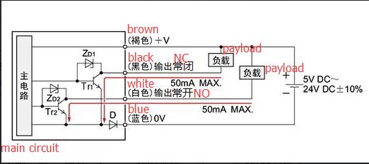
 ccm_sensor_en.jpg

                            brown +V -> 5V_EXT
                            blue 0V - > GND
                            black output 1 LIGHT ON -> ioX.in

                            Wiring should be ok because X and Y axis are working fine... problem seems to be on the use of 4 pcs of endstops for one axis...

                            jay_s_ukundefined 1 Reply Last reply 3 Sept 2021, 09:04 Reply Quote 0
                            • oliofundefined
                              oliof
                              last edited by 3 Sept 2021, 08:53

                              M584 X40.0 Y41.0 Z1:2:4:5 E20.0

                              Is this correct? Do you have X and Y on separate toolboards?

                              <>RatRig V-Minion Fly Super5Pro RRF<> V-Core 3.1 IDEX k*****r <> RatRig V-Minion SKR 2 Marlin<>

                              undefined 1 Reply Last reply 3 Sept 2021, 10:52 Reply Quote 0
                              • jay_s_ukundefined
                                jay_s_uk @Duncan
                                last edited by 3 Sept 2021, 09:04

                                @duncan are they all getting 5v and do the lights all go fully off (or on) when activated and not just dim?

                                Owns various duet boards and is the main wiki maintainer for the Teamgloomy LPC/STM32 port of RRF. Assume I'm running whatever the latest beta/stable build is

                                1 Reply Last reply Reply Quote 0
                                • undefined
                                  Duncan @oliof
                                  last edited by 3 Sept 2021, 10:52

                                  @oliof yes, I have two extension boards, those motors and endstops are working fine, they have their own external control drivers.

                                  @jay_s_uk yes, lights are working ok, now I have a differente situation I'm going to explain.

                                  I put a backup of the config files before using 4 endstops for Z axis and only the probe for Z that was working fine, so machine was working good. Then I updated only the config.g with the one defined with 4 endstops and still good... all motors of Z moving and homming with the probe...

                                  When I put the latest homez.g file the problem was again in the machine, so I made this change:

                                  This is the homez.g with the initial problems

                                  ; homez.g
                                  ; called to home the Z axis
                                  ;
                                  ; generated by RepRapFirmware Configuration Tool v3.1.4 on Fri Sep 04 2020 14:49:01 GMT+0800 (中国标准时间)
                                  G91              ; relative positioning
                                  G1 H2 Z10 F6000   ; lift Z relative to current position
                                  ;G1 H2 X510 Y510 F6000 ; go to first probe point
                                  G1 H1 Z-99999
                                  G90              ; absolute positioning
                                  G30              ; home Z by probing the bed - activar 3D Touch
                                  
                                  ; Uncomment the following lines to lift Z after probing
                                  ;G91             ; relative positioning
                                  ;G1 Z10 F100      ; lift Z relative to current positiond
                                  ;G90             ; absolute positioning
                                  

                                  This is the actual homez.g working somehow...

                                  ; homez.g
                                  ; called to home the Z axis
                                  ;
                                  ; generated by RepRapFirmware Configuration Tool v3.1.4 on Fri Sep 04 2020 14:49:01 GMT+0800 (中国标准时间)
                                  G91              ; relative positioning
                                  G1 H2 Z10 F300   ; lift Z relative to current position
                                  G90              ; absolute positioning
                                  G1 X510 Y510 F10000 ; go to first probe point
                                  G1 H1 Z-99999
                                  ;G1 X510 Y510 F3000 ; go to first probe point
                                  G30              ; home Z by probing the bed
                                  
                                  ; Uncomment the following lines to lift Z after probing
                                  ;G91             ; relative positioning
                                  ;G1 Z10 F300      ; lift Z relative to current positiond
                                  ;G90             ; absolute positioning
                                  

                                  So the only main change is that I put G90 before the first probe point movement and Z axis moving down looking for endstops... (but not for the probe touching).

                                  So I'm going to test now if once the machine hits the 4 endstops then go for the probe to touch the bed, that it's my objective, because I want to use the 4 endstops to calibrate the machine at the same heigh and then the probe for fine compensation of the bed.

                                  But I don't know if that will work if all the movement on Z is on negative direction or I should put the 4 endstops on Z positive and probe for Z negative...

                                  1 Reply Last reply Reply Quote 0
                                  • First post
                                    Last post
                                  Unless otherwise noted, all forum content is licensed under CC-BY-SA