Problems with endstops only working in one input
-
I think it may be some problem with the configuration of the board or some problem with the board... I explain the problem.
My setup is:
- DUET 3 MB6HC with 4 Nema 23 for Z axis connected and endstops photoelectric switch PM-Y44 (5-24V working)
- DUET 3 Expansion 1XD with 1 Nema 23 with external driver for X axis (endstop to mainboard directly)
- DUET 3 Expansion 1XD with 1 Nema 23 with external driver for Y axis (endstop to mainboard directly)
- DUET 3 Toolboard for extruder (Titan Aero with Volcano).
My config.g
; Network
M552 P0.0.0.0 S1                                        ; enable network and acquire dynamic address via DHCP
M586 P0 S1                                              ; enable HTTP
M586 P1 S0                                              ; disable FTP
M586 P2 S0                                              ; disable Telnet

; Drives

M584 X40.0 Y41.0 Z1:2:4:5 E20.0				; J- configuramos los motores X, Y, Z y E en cada posición de la placa principal o placas externas.
M671 X1115:1115:-15:-15 Y1360:-260:-260:1360 S0.5	; J- configuramos la posición de los husillos respecto el origen (0,0) de la cama (no de los finales de carrera)
;M584 X40.0						; set X driver
;M584 Y41.0 						; set Y driver
;M584 Z1:2:4:5 						; set Z driver
;M584 E20.0						; set E driver

M569 P0 S0                                           ; physical drive 0.0 goes forwards
M569 P1 S0                                           ; physical drive 0.1 goes forwards
M569 P2 S0                                           ; physical drive 0.2 goes forwards
M569 P3 S0                                           ; physical drive 0.3 goes forwards
M569 P4 S0                                           ; physical drive 0.4 goes forwards
M569 P5 S0										; physical drive 0.5 goes forwards
G4 S1 													;wait for expansion boards to start
M569 P40.0 S1 R0 T2.7										; change enable polarity, active = disable drive
M569 P41.0 S0 R0 T2.7
M569 P20.0 S1

                  				; set drive mapping
M350 X16 Y16 Z32 E16 I1                           			; configure microstepping with interpolation
M92 X133.333 Y133.333 Z1280 E420.00	         			; set steps per mm
M566 X900.00 Y900.00 Z12 E120.00			       		; set maximum instantaneous speed changes (mm/min)
M203 X6000.00 Y6000.00 Z180 E1200.00					; set maximum speeds (mm/min)
M201 X500.00 Y500.00 Z100.00 E250.00		    			; set accelerations (mm/s^2)
M906 X1000 Y1000 Z3000 E800 I30		                    		; set motor currents (mA) and motor idle factor in per cent
G21 									; TRABAJO EN MM
G90 									; TRABAHO EN CORDENADAS ABSOLUTAS
M84 S30                                                 		; Set idle timeout

; Axis Limits
M208 X-50 Y-27 Z0 S1                                        		; set axis minima
M208 X1100 Y1100 Z1000 S0                                  		; set axis maxima

; Endstops
M574 X1 S1 P"io0.in"                                    ; configure active-high endstop for low end on X via pin io1.in
M574 Y1 S1 P"io1.in"                                        ; configure active-high endstop for low end on Y via pin io2.in
;M574 P"^io3.in+^io4.in+^io5.in+^io6.in" Z1 S1		    ; configuramos finales de carrera eje Z según orden de motores

; Z-Probe
;M950 S0 C"20.io0.out"                           ; create servo pin 0 for BLTouch
;M558 P9 C"^20.io0.in" H10 F120 T6000             ; set Z probe type to bltouch and the dive height + speeds
;G31 P500 X20 Y40 Z0                          ; set Z probe trigger value, offset and trigger height
;M557 X50:1100 Y70:1100 S500                     ; define mesh grid

; Heaters
;M308 S0 P"temp0" Y"thermistor" B4725 C7.06e-8            ; configure sensor 0 as thermistor on pin temp0
;M950 H0 C"out0" T0                                      ; create bed heater output on out0 and map it to sensor 0
;M307 H0 B1 S1.00                                        ; enable bang-bang mode for the bed heater and set PWM limit
;M140 H0                                                 ; map heated bed to heater 0
;M143 H0 S120                                            ; set temperature limit for heater 0 to 120C
M308 S0 P"20.temp0" Y"thermistor" B4725 C7.06e-8             ; configure sensor 1 as thermistor on pin temp1
M950 H1 C"20.out0" T0                                      ; create nozzle heater output on out1 and map it to sensor 1
M307 H0 B0 S1.00                                        ; disable bang-bang mode for heater  and set PWM limit
M143 H0 S120                                           ; set temperature limit for heater 0 to 120C


; Fans
M950 F0 C"20.out1" Q500                                    ; create fan 0 on pin out7 and set its frequency

M106 P0 S255 H0 T50
M106 P0 S0; Herramienta 2 PCF

; Tools
M563 P0 D0 H1 F0                                        ; define tool 0
G10 P0 X0 Y0 Z0                                         ; set tool 0 axis offsets
;G10 P0 R0 S0                                            ; set initial tool 0 active and standby temperatures to 0C


; Custom settings are not defined
;M556 S100 X0 Y0 Z0 ; Put your axis compensation here
;M912 P9 S0 ; Put your CPU temperature sensor correction here
;M501 ; Run config-override.g
;T0 ; Select the first head

; Miscellaneous
M575 P1 S1 B57600                                       ; enable support for PanelDue
M564 H0
M302 P1
My home X
; homex.g
; called to home the X axis
;
; generated by RepRapFirmware Configuration Tool v3.1.4 on Fri Sep 04 2020 14:48:59 GMT+0800 (中国标准时间)
G91               ; relative positioning
G1 H2 Z5 F6000    ; lift Z relative to current position
G1 H1 X-1100 F6000 ; move quickly to X axis endstop and stop there (first pass)
G1 H2 X10 F6000    ; go back a few mm
G1 H1 X-1100 F200  ; move slowly to X axis endstop once more (second pass)
G1 H2 Z-5 F6000   ; lower Z again
G90               ; absolute positioning
My home Y
; homey.g
; called to home the Y axis
;
; generated by RepRapFirmware Configuration Tool v3.1.4 on Fri Sep 04 2020 14:49:01 GMT+0800 (中国标准时间)
G91               ; relative positioning
G1 H2 Z5 F3000    ; lift Z relative to current position
G1 H1 Y-1100 F3000 ; move quickly to Y axis endstop and stop there (first pass)
G1 H2 Y10 3000	; go back a few mm
G1 H1 Y-1100 F200  ; move slowly to Y axis endstop once more (second pass)
G1 H2 Z-5 F3000   ; lower Z again
G90               ; absolute positioning
My home Z
; homez.g
; called to home the Z axis
;
; generated by RepRapFirmware Configuration Tool v3.1.4 on Fri Sep 04 2020 14:49:01 GMT+0800 (中国标准时间)
G91              ; relative positioning
G1 H2 Z10 F6000   ; lift Z relative to current position
G1 H2 X510 Y510 F6000 ; go to first probe point
G1 H1 Z-99999
G90              ; absolute positioning
;G30              ; home Z by probing the bed

; Uncomment the following lines to lift Z after probing
;G91             ; relative positioning
;G1 Z10 F100      ; lift Z relative to current positiond
;G90             ; absolute positioning
My bed G
; bed.g
; called to perform automatic bed compensation via G32
;
; generated by RepRapFirmware Configuration Tool v3.1.4 on Mon Aug 31 2020 15:45:57 GMT+0800 (中国标准时间)

;M561 ; clear any bed transform
;G28 XY
;G29  ; probe the bed and enable compensation


G28
G30 P0 X1100 Y1360 Z-99999 		; calibra junto motor (1)
G30 P1 X1100 Y30 Z-99999		; calibra junto motor (2)
G30 P2 X20 Y30 Z-99999			; calibra junto motor (4)
G30 P3 X20 Y1360 Z-99999		; calibra junto motor (5)
The problem we have is that only "io1.in" on mainboard is seems to work.... we connect other endstops in other inputs (from 0 to 9) and endstop doesn't stop the axis.... we also try to use the inputs from Expansions boards and doesn't get them working also... (we config them as P"40.io0.in" because the expansion board 1 is with 40 address).
Do you know if we have some bad configuration or maybe some problem with the board?
Thank you
-
@duncan which firmware versions are you running, on the main board and on the expansion boards?Use M115 to check. Version 3.3 is current.
Have you tried testing the endstops? You can monitor them by opening the Object Model Browser in DWC, expanding sensors->endstops and then the endstop numbers, and watching the "triggered" value.
What type of endstops are they?
PS. in this line:
;M574 P"^io3.in+^io4.in+^io5.in+^io6.in" Z1 S1 ; configuramos finales de carrera eje Z según orden de motores
Remove the ^ characters. Internal pullup resistors should never be enabled on Duet 3 series electronics.
-
@dc42 firmware version is 3.3 in all boards, already updated it before setting up all the system.
I have 7 pcs of endstops, if I use them on io1.in they all work and stop the Y axis, if I put other io number on same axis and test the endstops they don't work... that's the strange thing that is getting me crazy.
Enstops are this: https://www.digikey.es/product-detail/es/panasonic-industrial-automation-sales/PM-Y44/1110-2019-ND/3899551
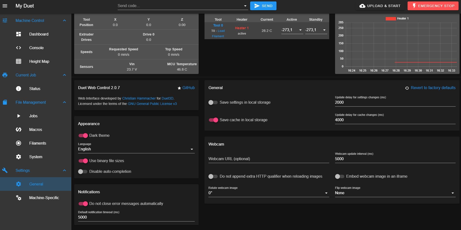
Sorry but I can't find the Object Model Browser... I'm a total newbie in this... only thing I can find is in settings - Machine properties and endstop hit.... that I have the only one connected on port 1 as No (because Y axis is on the middle) and other are YES because they don't have connected nothing at this momment, don't know if that helps
-
@duncan said in Problems with endstops only working in one input:
@dc42 firmware version is 3.3 in all boards, already updated it before setting up all the system.
Yes, but did you check using M115?
-
@duncan said in Problems with endstops only working in one input:
Sorry but I can't find the Object Model Browser...
You have to start it first. Go to Settings/General and click the Built-In Plugins tab. Then find Object model browser and start it.
-
-
@duncan you need to upgrade duet web control
https://github.com/Duet3D/RepRapFirmware/releases/download/3.3/DuetWebControl-SD.zip -
@jay_s_uk thank you, now I can see the plugins tabs.
@dc42 now I can see the triggered value and in port 0 for example even with the endstop pushed (with a metal) it's always false, if we disconnect the endstop it changes to true.
But in port 1, with endstop pushed it shows false but sometimes the value change some miliseconds to true and again false... and thats repeats every few seconds...
Other issue is that even I have defined the Z endstops for the 4 motors with M574 Z1 S1 P"io3.in+io4.in+io5.in+io6.in" I can't see those endstops on Object Model Browser but instead I see the port 2 that I'm not using...
-
@duncan said in Problems with endstops only working in one input:
now I can see the triggered value and in port 0 for example even with the endstop pushed (with a metal) it's always false, if we disconnect the endstop it changes to true.
That suggests to me that you have not connected that optical sensor correctly to the port, or that its leakage current is too high. How have you connected it to the I/O port? You may need to add an extra pullup resistor to control the leakage current.
-
@dc42 they're connected with no resistor. I read this DS (https://www.farnell.com/datasheets/2243844.pdf) and are connected in Light ON mode.
They're supposed to work between 5 and 24V, so I thought nothing more was needed.
-
@duncan said in Problems with endstops only working in one input:
@dc42 they're connected with no resistor. I read this DS (https://www.farnell.com/datasheets/2243844.pdf) and are connected in Light ON mode.
They're supposed to work between 5 and 24V, so I thought nothing more was needed.
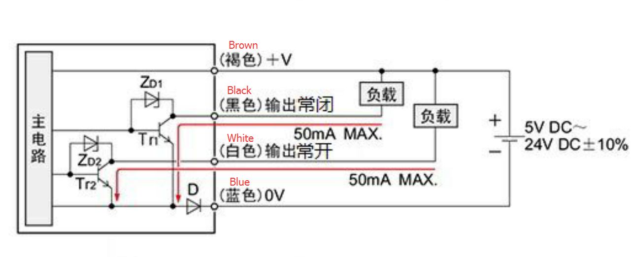
Which sensor wire have you connected to which pin on the Duet?
Those sensors are designed to handle up to 50mA current. It is entirely possible that they may leak too much for light loads, such as the input of a Duet. Depending on what amplifier circuit they contain, it may also be that a small amount of light leaking into the photodetector might cause them to sink enough current to trigger the Duet.
-
-
Hello again,
I've been out for vacations but I'm back now with this project.
CCM sent me other image of sensors with english information that was missing on previous one:
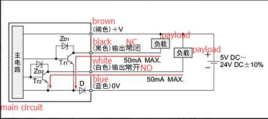
Any suggestions?
-
@duncan I think the problem may be the diode D that they have added, probably for reverse polarity detection. That is probably causing the output to be greater than 1V when the sensor is triggered. Can you measure that output voltage using a multimeter?
-
@dc42 the problem is solved... the issue was that my friend didn't put the wires in the right position after some changes and that was making all the malfunctions, sorry for all the mess created about that
 . Now they're working fine finally. Thanks for the help.