Problems with endstops only working in one input
-
@dc42 firmware version is 3.3 in all boards, already updated it before setting up all the system.
I have 7 pcs of endstops, if I use them on io1.in they all work and stop the Y axis, if I put other io number on same axis and test the endstops they don't work... that's the strange thing that is getting me crazy.
Enstops are this: https://www.digikey.es/product-detail/es/panasonic-industrial-automation-sales/PM-Y44/1110-2019-ND/3899551
Sorry but I can't find the Object Model Browser... I'm a total newbie in this... only thing I can find is in settings - Machine properties and endstop hit.... that I have the only one connected on port 1 as No (because Y axis is on the middle) and other are YES because they don't have connected nothing at this momment, don't know if that helps
-
@duncan said in Problems with endstops only working in one input:
@dc42 firmware version is 3.3 in all boards, already updated it before setting up all the system.
Yes, but did you check using M115?
Duet WiFi hardware designer and firmware engineer
Please do not ask me for Duet support via PM or email, use the forum
http://www.escher3d.com, https://miscsolutions.wordpress.com -
@duncan said in Problems with endstops only working in one input:
Sorry but I can't find the Object Model Browser...
You have to start it first. Go to Settings/General and click the Built-In Plugins tab. Then find Object model browser and start it.
-
-
@duncan you need to upgrade duet web control
https://github.com/Duet3D/RepRapFirmware/releases/download/3.3/DuetWebControl-SD.zip -
@jay_s_uk thank you, now I can see the plugins tabs.
@dc42 now I can see the triggered value and in port 0 for example even with the endstop pushed (with a metal) it's always false, if we disconnect the endstop it changes to true.
But in port 1, with endstop pushed it shows false but sometimes the value change some miliseconds to true and again false... and thats repeats every few seconds...
Other issue is that even I have defined the Z endstops for the 4 motors with M574 Z1 S1 P"io3.in+io4.in+io5.in+io6.in" I can't see those endstops on Object Model Browser but instead I see the port 2 that I'm not using...
-
@duncan said in Problems with endstops only working in one input:
now I can see the triggered value and in port 0 for example even with the endstop pushed (with a metal) it's always false, if we disconnect the endstop it changes to true.
That suggests to me that you have not connected that optical sensor correctly to the port, or that its leakage current is too high. How have you connected it to the I/O port? You may need to add an extra pullup resistor to control the leakage current.
Duet WiFi hardware designer and firmware engineer
Please do not ask me for Duet support via PM or email, use the forum
http://www.escher3d.com, https://miscsolutions.wordpress.com -
@dc42 they're connected with no resistor. I read this DS (https://www.farnell.com/datasheets/2243844.pdf) and are connected in Light ON mode.
They're supposed to work between 5 and 24V, so I thought nothing more was needed.
-
@duncan said in Problems with endstops only working in one input:
@dc42 they're connected with no resistor. I read this DS (https://www.farnell.com/datasheets/2243844.pdf) and are connected in Light ON mode.
They're supposed to work between 5 and 24V, so I thought nothing more was needed.
Which sensor wire have you connected to which pin on the Duet?
Those sensors are designed to handle up to 50mA current. It is entirely possible that they may leak too much for light loads, such as the input of a Duet. Depending on what amplifier circuit they contain, it may also be that a small amount of light leaking into the photodetector might cause them to sink enough current to trigger the Duet.
Duet WiFi hardware designer and firmware engineer
Please do not ask me for Duet support via PM or email, use the forum
http://www.escher3d.com, https://miscsolutions.wordpress.com -
-
Hello again,
I've been out for vacations but I'm back now with this project.
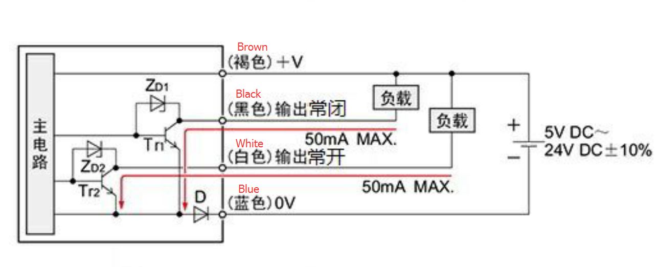
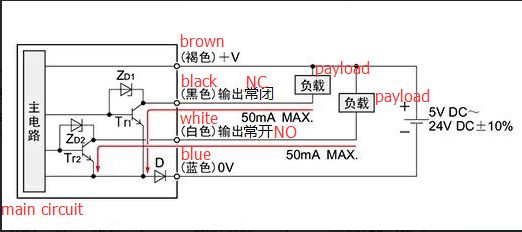
CCM sent me other image of sensors with english information that was missing on previous one:
Any suggestions?
-
@duncan I think the problem may be the diode D that they have added, probably for reverse polarity detection. That is probably causing the output to be greater than 1V when the sensor is triggered. Can you measure that output voltage using a multimeter?
Duet WiFi hardware designer and firmware engineer
Please do not ask me for Duet support via PM or email, use the forum
http://www.escher3d.com, https://miscsolutions.wordpress.com -
@dc42 the problem is solved... the issue was that my friend didn't put the wires in the right position after some changes and that was making all the malfunctions, sorry for all the mess created about that
 . Now they're working fine finally. Thanks for the help.