Tool board - no response
-
hey
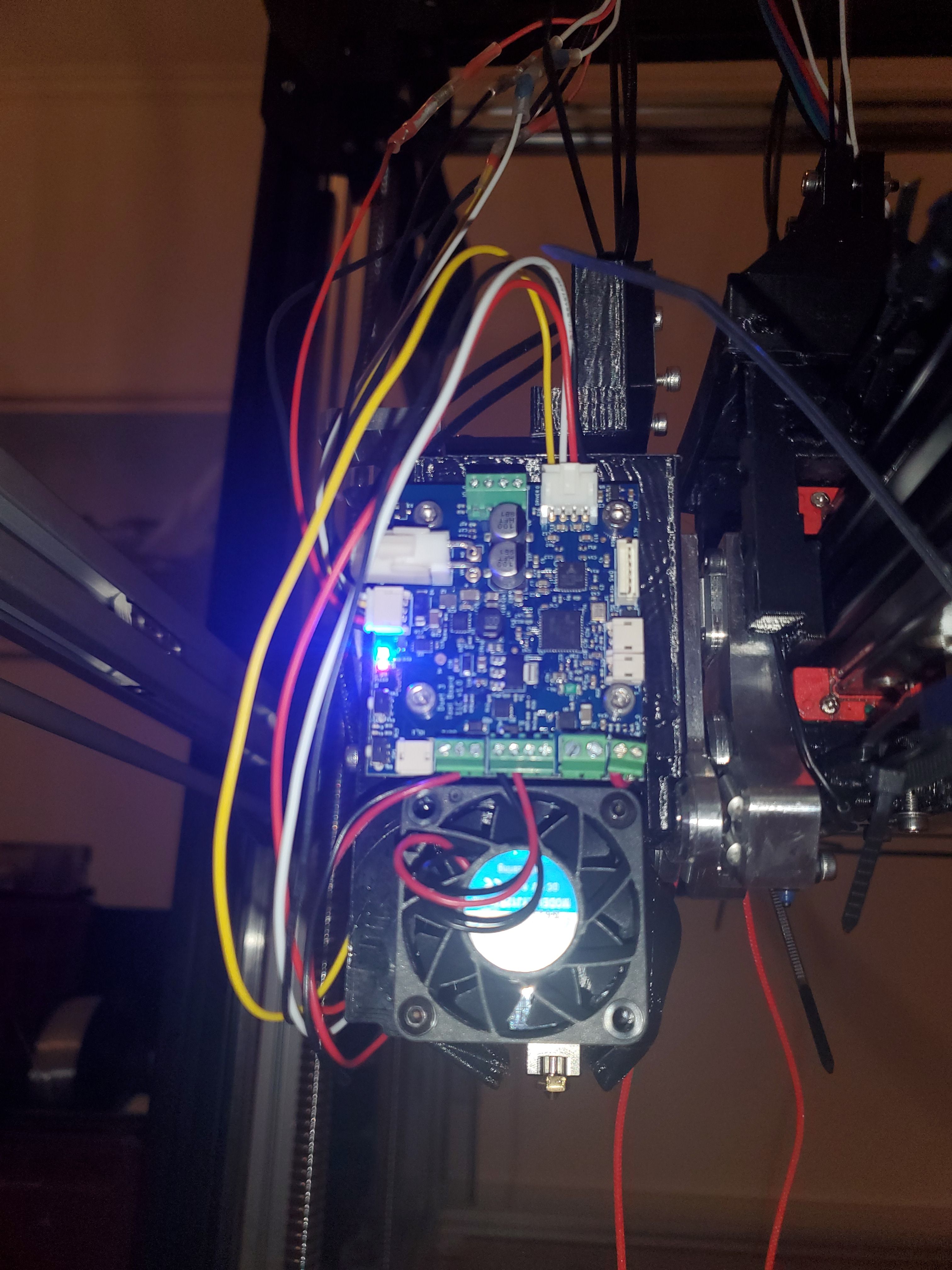
I try to connect my first toolboard via the tool distribution board and the expansion board... but no information from the toolboard is shwon in the dwc. I have connected tool distribution board and toolboard (can) with a thin cupper cable. I hope that's ok?
may you can help me.
thanks
R.G.

; Configuration file for Duet 3 (firmware version 3) ; executed by the firmware on start-up ; ; generated by RepRapFirmware Configuration Tool v3.2.3 on Mon Aug 02 2021 16:15:35 GMT+0200 (Mitteleuropäische Sommerzeit) ; General preferences G90 ; send absolute coordinates... M83 ; ...but relative extruder moves M550 P"Duet 3" ; set printer name M552 S1 P192.168.2.108 ; Wifi ; Drives M569 P0.0 S1 ; physical drive 0.0 goes forwards M569 P0.1 S1 ; physical drive 0.1 goes forwards M569 P0.2 S0 ; physical drive 0.2 goes forwards M569 P0.3 S0 ; physical drive 0.2 goes forwards M569 P0.4 S0 ; physical drive 0.2 goes forwards M569 P0.5 S0 ; physical drive 0.2 goes forwards M569 P121.0 S1 ; physical drive 121.0 goes forwards M569 P122.0 S1 ; physical drive 122.0 goes forwards M569 P123.0 S1 ; physical drive 123.0 goes forwards M584 M584 X1.1 Y0.0:0.1 Z0.2:0.3:0.4:0.5 E121.0:122.0:123.0 ; set drive mapping M350 X16 Y16 Z16 E16:16:16 I1 ; configure microstepping with interpolation M92 X160.00 Y160.00 Z640.00 E409.00:409.00:409.00 ; set steps per mm M566 X900.00 Y900.00 Z60.00 E3000.00:3000.00:3000.00 ; set maximum instantaneous speed changes (mm/min) M203 X12000.00 Y12000.00 Z6000.00 E6000.00:6000.00:6000.00 ; set maximum speeds (mm/min) M201 X500.00 Y500.00 Z300.00 E250.00:250.00:250.00 ; set accelerations (mm/s^2) M906 X1300 Y1300 Z2500 E1000:1000:1000 I30 ; set motor currents (mA) and motor idle factor in per cent M84 S30 ; Set idle timeout ; Axis Limits M208 X-10 Y-10 Z10 S1 ; set axis minima M208 X1030 Y1030 Z1030 S0 ; set axis maxima ; Endstops M574 X2 S1 P"^io3.in" ; configure active-high endstop for high end on X via pin ^io3.in M574 Y2 S1 P"^io1.in" ; configure active-high endstop for high end on Y via pin ^io1.in M574 Z1 S1 P"^io2.in" ; configure active-high endstop for low end on Z via pin ^io2.in ; Z-Probe M558 P0 H-5 F300 T300 ; disable Z probe but set dive height, probe speed and travel speed M556 S50 X0 Y0 Z70 ; set orthogonal axis compensation parameters M557 X10:10 Y10:10 S20 ; define mesh grid ; Heaters M308 S0 P"temp0" Y"thermistor" T100000 B4138 ; configure sensor 0 as thermistor on pin temp0 M950 H0 C"out0" T0 ; create bed heater output on out0 and map it to sensor 0 M307 H0 B0 R0.243 C586.2 D33.87 S1.00 V220.0 ; disable bang-bang mode for the bed heater and set PWM limit M140 H0 ; map heated bed to heater 0 M143 H0 S120 ; set temperature limit for heater 0 to 120C M308 S1 P"121.temp0" Y"pt1000" R2200 ; configure sensor 1 as PT1000 on pin 121.temp0 M950 H1 C"121.out0" T1 ; create nozzle heater output on 121.out0 and map it to sensor 1 M307 H1 B0 S1.00 ; disable bang-bang mode for heater and set PWM limit M143 H1 S250 ; set temperature limit for heater 1 to 250C M308 S2 P"122.temp0" Y"pt1000" R2200 ; configure sensor 2 as PT1000 on pin 122.temp0 M950 H2 C"122.out0" T2 ; create nozzle heater output on 122.out0 and map it to sensor 2 M307 H2 B0 S1.00 ; disable bang-bang mode for heater and set PWM limit M143 H2 S250 ; set temperature limit for heater 2 to 250C M308 S3 P"123.temp0" Y"pt1000" R2200 ; configure sensor 3 as PT1000 on pin 123.temp0 M950 H3 C"123.out0" T3 ; create nozzle heater output on 123.out0 and map it to sensor 3 M307 H3 B0 S1.00 ; disable bang-bang mode for heater and set PWM limit M143 H3 S250 ; set temperature limit for heater 3 to 250C ; Fans M950 F0 C"121.out1" Q500 ; create fan 0 on pin 121.out1 and set its frequency M106 P0 S0 H-1 ; set fan 0 value. Thermostatic control is turned off M950 F1 C"121.out2" Q500 ; create fan 1 on pin 121.out2 and set its frequency M106 P1 S1 H1 T45 ; set fan 1 value. Thermostatic control is turned on M950 F2 C"122.out1" Q500 ; create fan 2 on pin 122.out1 and set its frequency M106 P2 S1 H-1 ; set fan 2 value. Thermostatic control is turned off M950 F3 C"122.out2" Q500 ; create fan 3 on pin 122.out2 and set its frequency M106 P3 S1 H2 T45 ; set fan 3 value. Thermostatic control is turned on M950 F4 C"123.out1" Q500 ; create fan 4 on pin 123.out1 and set its frequency M106 P4 S1 H-1 ; set fan 4 value. Thermostatic control is turned off M950 F5 C"123.out2" Q500 ; create fan 5 on pin 123.out2 and set its frequency M106 P5 S1 H3 T45 ; set fan 5 value. Thermostatic control is turned on M950 F6 C"out4" Q500 ; create fan 6 on pin out4 and set its frequency M106 P6 S1 H-1 ; set fan 6 value. Thermostatic control is turned off M950 F7 C"out5" Q500 ; create fan 7 on pin out5 and set its frequency M106 P7 S1 H T45 ; set fan 7 value. Thermostatic control is turned on ; Tools M563 P0 D0 H1 F0 ; define tool 0 G10 P0 X30 Y28.25 Z45 ; set tool 0 axis offsets G10 P0 R0 S0 ; set initial tool 0 active and standby temperatures to 0C M563 P1 D1 H2 F2 ; define tool 1 G10 P1 X0 Y0 Z0 ; set tool 1 axis offsets G10 P1 R0 S0 ; set initial tool 1 active and standby temperatures to 0C M563 P2 D2 H3 F4 ; define tool 2 G10 P2 X0 Y0 Z0 ; set tool 2 axis offsets G10 P2 R0 S0 ; set initial tool 2 active and standby temperatures to 0C ; Custom settings are not defined ; Miscellaneous M911 S10 R11 P"M913 X0 Y0 G91 M83 G1 Z3 E-5 F1000" ; set voltage thresholds and actions to run on power loss -
@barbarossa-cologne you are running incompatible versions of main board and tool board firmware. I suggest you upgrade both to version 3.3.
-
@dc42 ok update done. thanks
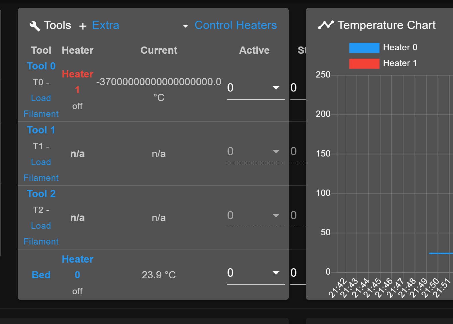
Now, I have very crazy number on thermistor for tool 0.

-
@barbarossa-cologne
-
M307 H0 B0 R0.243 C586.2 D33.87 S1.00 V220.0
Did you manually set V220?
Vnnn VIN supply voltage at which the A parameter was calibrated (RepRapFirmware 1.20 and later). This allows the PID controller to compensate for changes in supply voltage. A value of zero disables compensation for changes in supply voltage. Use V0 for AC mains powered heaters. (V0 is the default. Leaving off V is the same as V0)
V220 would mean your heater is mains powered? But if that is the case, it suggests using V0 instead.
-
I did it manually
I changed the number to 0.
Same problem....
-
No that's fine. And it's not related to your tool temperature anyway, it just stuck out to me.
Can you please try adding a G4 S4 to the start of your config.g to allow for the tool boards to power up before they are sent commands and see if that has any impact on the spurious reading.
Can you also check that your DWC version matches the firmware 3.3?
Can you send M122 and M122 B121 and post the results?
-
@phaedrux
After setting G4 S4 in front of the g.code --> same problemM122
=== Diagnostics ===
RepRapFirmware for Duet 3 MB6HC version 3.3 (2021-06-15 21:45:47) running on Duet 3 MB6HC v1.01 or later (standalone mode)
Board ID: 08DJM-956L2-G43S8-6J9D0-3S46R-9U2AD
Used output buffers: 3 of 40 (13 max)
=== RTOS ===
Static ram: 150904
Dynamic ram: 92748 of which 100 recycled
Never used RAM 110440, free system stack 200 words
Tasks: NETWORK(ready,12.0%,212) ETHERNET(notifyWait,0.1%,124) HEAT(delaying,0.0%,331) Move(notifyWait,0.0%,352) CanReceiv(notifyWait,0.1%,799) CanSender(notifyWait,0.0%,374) CanClock(delaying,0.0%,339) TMC(notifyWait,6.8%,93) MAIN(running,33.2%,1096) IDLE(ready,47.8%,29), total 100.0%
Owned mutexes:
=== Platform ===
Last reset 00:00:51 ago, cause: software
Last software reset at 2021-08-11 22:31, reason: User, GCodes spinning, available RAM 110464, slot 1
Software reset code 0x0003 HFSR 0x00000000 CFSR 0x00000000 ICSR 0x0044a000 BFAR 0x00000000 SP 0x00000000 Task MAIN Freestk 0 n/a
Error status: 0x00
Step timer max interval 127
MCU temperature: min 39.8, current 40.2, max 41.3
Supply voltage: min 24.0, current 24.0, max 24.0, under voltage events: 0, over voltage events: 0, power good: yes
12V rail voltage: min 12.1, current 12.2, max 12.2, under voltage events: 0
Heap OK, handles allocated/used 0/0, heap memory allocated/used/recyclable 0/0/0, gc cycles 0
Driver 0: position 0, standstill, reads 25598, writes 14 timeouts 0, SG min/max 0/0
Driver 1: position 0, standstill, reads 25598, writes 14 timeouts 0, SG min/max 0/0
Driver 2: position 0, standstill, reads 25598, writes 14 timeouts 0, SG min/max 0/0
Driver 3: position 0, standstill, reads 25599, writes 14 timeouts 0, SG min/max 0/0
Driver 4: position 0, standstill, reads 25599, writes 14 timeouts 0, SG min/max 0/0
Driver 5: position 0, standstill, reads 25599, writes 14 timeouts 0, SG min/max 0/0
Date/time: 2021-08-11 22:32:07
Slowest loop: 9.13ms; fastest: 0.05ms
=== Storage ===
Free file entries: 10
SD card 0 detected, interface speed: 25.0MBytes/sec
SD card longest read time 2.3ms, write time 0.0ms, max retries 0
=== Move ===
DMs created 125, maxWait 0ms, bed compensation in use: none, comp offset 0.000
=== MainDDARing ===
Scheduled moves 0, completed moves 0, hiccups 0, stepErrors 0, LaErrors 0, Underruns [0, 0, 0], CDDA state -1
=== AuxDDARing ===
Scheduled moves 0, completed moves 0, hiccups 0, stepErrors 0, LaErrors 0, Underruns [0, 0, 0], CDDA state -1
=== Heat ===
Bed heaters = 0 -1 -1 -1 -1 -1 -1 -1 -1 -1 -1 -1, chamberHeaters = -1 -1 -1 -1
=== GCodes ===
Segments left: 0
Movement lock held by null
HTTP is idle in state(s) 0
Telnet is idle in state(s) 0
File is idle in state(s) 0
USB is idle in state(s) 0
Aux is idle in state(s) 0
Trigger is idle in state(s) 0
Queue is idle in state(s) 0
LCD is idle in state(s) 0
SBC is idle in state(s) 0
Daemon is idle in state(s) 0
Aux2 is idle in state(s) 0
Autopause is idle in state(s) 0
Code queue is empty.
=== CAN ===
Messages queued 450, received 364, lost 67, longest wait 2ms for reply type 6049, peak Tx sync delay 6, free buffers 49 (min 48), ts 257/256/0
Tx timeouts 0,0,0,0,0,0
=== Network ===
Slowest loop: 17.57ms; fastest: 0.02ms
Responder states: HTTP(0) HTTP(0) HTTP(0) HTTP(0) HTTP(0) HTTP(0) FTP(0) Telnet(0), 0 sessions Telnet(0), 0 sessions
HTTP sessions: 1 of 8- Ethernet -
State: active
Error counts: 0 0 1 0 0
Socket states: 5 2 2 2 2 0 0 0
; Configuration file for Duet 3 (firmware version 3) ; executed by the firmware on start-up ; ; generated by RepRapFirmware Configuration Tool v3.2.3 on Mon Aug 02 2021 16:15:35 GMT+0200 (Mitteleuropäische Sommerzeit) ; General preferences G90 ; send absolute coordinates... M83 ; ...but relative extruder moves M550 P"Duet 3" ; set printer name M552 S1 P192.168.2.108 ; Wifi G4 S4 ; Drives M569 P0.0 S1 ; physical drive 0.0 goes forwards M569 P0.1 S1 ; physical drive 0.1 goes forwards M569 P0.2 S0 ; physical drive 0.2 goes forwards M569 P0.3 S0 ; physical drive 0.2 goes forwards M569 P0.4 S0 ; physical drive 0.2 goes forwards M569 P0.5 S0 ; physical drive 0.2 goes forwards M569 P121.0 S1 ; physical drive 121.0 goes forwards M569 P122.0 S1 ; physical drive 122.0 goes forwards M569 P123.0 S1 ; physical drive 123.0 goes forwards M584 M584 X1.1 Y0.0:0.1 Z0.2:0.3:0.4:0.5 E121.0:122.0:123.0 ; set drive mapping M350 X16 Y16 Z16 E16:16:16 I1 ; configure microstepping with interpolation M92 X160.00 Y160.00 Z640.00 E409.00:409.00:409.00 ; set steps per mm M566 X900.00 Y900.00 Z60.00 E3000.00:3000.00:3000.00 ; set maximum instantaneous speed changes (mm/min) M203 X12000.00 Y12000.00 Z6000.00 E6000.00:6000.00:6000.00 ; set maximum speeds (mm/min) M201 X500.00 Y500.00 Z300.00 E250.00:250.00:250.00 ; set accelerations (mm/s^2) M906 X1300 Y1300 Z2500 E1000:1000:1000 I30 ; set motor currents (mA) and motor idle factor in per cent M84 S30 ; Set idle timeout ; Axis Limits M208 X-10 Y-10 Z10 S1 ; set axis minima M208 X1030 Y1030 Z1030 S0 ; set axis maxima ; Endstops M574 X2 S1 P"^io3.in" ; configure active-high endstop for high end on X via pin ^io3.in M574 Y2 S1 P"^io1.in" ; configure active-high endstop for high end on Y via pin ^io1.in M574 Z1 S1 P"^io2.in" ; configure active-high endstop for low end on Z via pin ^io2.in ; Z-Probe M558 P0 H-5 F300 T300 ; disable Z probe but set dive height, probe speed and travel speed M556 S50 X0 Y0 Z70 ; set orthogonal axis compensation parameters M557 X10:10 Y10:10 S20 ; define mesh grid ; Heaters M308 S0 P"temp0" Y"thermistor" T100000 B4138 ; configure sensor 0 as thermistor on pin temp0 M950 H0 C"out0" T0 ; create bed heater output on out0 and map it to sensor 0 M307 H0 B0 R0.243 C586.2 D33.87 S1.00 V0 ; disable bang-bang mode for the bed heater and set PWM limit M140 H0 ; map heated bed to heater 0 M143 H0 S120 ; set temperature limit for heater 0 to 120C M308 S1 P"121.temp0" Y"pt1000" R2200 ; configure sensor 1 as PT1000 on pin 121.temp0 M950 H1 C"121.out0" T1 ; create nozzle heater output on 121.out0 and map it to sensor 1 M307 H1 B0 S1.00 ; disable bang-bang mode for heater and set PWM limit M143 H1 S250 ; set temperature limit for heater 1 to 250C M308 S2 P"122.temp0" Y"pt1000" R2200 ; configure sensor 2 as PT1000 on pin 122.temp0 M950 H2 C"122.out0" T2 ; create nozzle heater output on 122.out0 and map it to sensor 2 M307 H2 B0 S1.00 ; disable bang-bang mode for heater and set PWM limit M143 H2 S250 ; set temperature limit for heater 2 to 250C M308 S3 P"123.temp0" Y"pt1000" R2200 ; configure sensor 3 as PT1000 on pin 123.temp0 M950 H3 C"123.out0" T3 ; create nozzle heater output on 123.out0 and map it to sensor 3 M307 H3 B0 S1.00 ; disable bang-bang mode for heater and set PWM limit M143 H3 S250 ; set temperature limit for heater 3 to 250C ; Fans M950 F0 C"121.out1" Q500 ; create fan 0 on pin 121.out1 and set its frequency M106 P0 S0 H-1 ; set fan 0 value. Thermostatic control is turned off M950 F1 C"121.out2" Q500 ; create fan 1 on pin 121.out2 and set its frequency M106 P1 S1 H1 T45 ; set fan 1 value. Thermostatic control is turned on M950 F2 C"122.out1" Q500 ; create fan 2 on pin 122.out1 and set its frequency M106 P2 S1 H-1 ; set fan 2 value. Thermostatic control is turned off M950 F3 C"122.out2" Q500 ; create fan 3 on pin 122.out2 and set its frequency M106 P3 S1 H2 T45 ; set fan 3 value. Thermostatic control is turned on M950 F4 C"123.out1" Q500 ; create fan 4 on pin 123.out1 and set its frequency M106 P4 S1 H-1 ; set fan 4 value. Thermostatic control is turned off M950 F5 C"123.out2" Q500 ; create fan 5 on pin 123.out2 and set its frequency M106 P5 S1 H3 T45 ; set fan 5 value. Thermostatic control is turned on M950 F6 C"out4" Q500 ; create fan 6 on pin out4 and set its frequency M106 P6 S1 H-1 ; set fan 6 value. Thermostatic control is turned off M950 F7 C"out5" Q500 ; create fan 7 on pin out5 and set its frequency M106 P7 S1 H T45 ; set fan 7 value. Thermostatic control is turned on ; Tools M563 P0 D0 H1 F0 ; define tool 0 G10 P0 X30 Y28.25 Z45 ; set tool 0 axis offsets G10 P0 R0 S0 ; set initial tool 0 active and standby temperatures to 0C M563 P1 D1 H2 F2 ; define tool 1 G10 P1 X0 Y0 Z0 ; set tool 1 axis offsets G10 P1 R0 S0 ; set initial tool 1 active and standby temperatures to 0C M563 P2 D2 H3 F4 ; define tool 2 G10 P2 X0 Y0 Z0 ; set tool 2 axis offsets G10 P2 R0 S0 ; set initial tool 2 active and standby temperatures to 0C ; Custom settings are not defined ; Miscellaneous M911 S10 R11 P"M913 X0 Y0 G91 M83 G1 Z3 E-5 F1000" ; set voltage thresholds and actions to run on power loss - Ethernet -
-
@barbarossa-cologne M122 B121
Diagnostics for board 121:
Duet TOOL1LC firmware version 3.3 (2021-06-15 16:12:58)
Bootloader ID: not available
Never used RAM 3636, free system stack 2789 words
Tasks: Move(notifyWait,0.0%,153) HEAT(delaying,0.1%,117) CanAsync(notifyWait,0.0%,65) CanRecv(notifyWait,0.0%,76) CanClock(notifyWait,0.0%,65) TMC(delaying,2.9%,57) MAIN(running,92.1%,350) IDLE(ready,0.0%,41) AIN(delaying,4.9%,142), total 100.0%
Last reset 00:03:41 ago, cause: software
Last software reset data not available
Driver 0: position 0, 409.0 steps/mm, standstill, SG min/max 0/0, read errors 0, write errors 1, ifcnt 61, reads 45026, writes 13, timeouts 0, DMA errors 0, steps req 0 done 0
Moves scheduled 0, completed 0, in progress 0, hiccups 0, step errors 0, maxPrep 0, maxOverdue 0, maxInc 0, mcErrs 0, gcmErrs 0
Peak sync jitter 0/9, peak Rx sync delay 208, resyncs 0/0, no step interrupt scheduled
VIN: 24.1V
MCU temperature: min 38.4C, current 38.5C, max 38.8C
Ticks since heat task active 186, ADC conversions started 220384, completed 220383, timed out 0, errs 0
Last sensors broadcast 0x00000002 found 1 191 ticks ago, loop time 0
CAN messages queued 2487, send timeouts 0, received 1957, lost 0, free buffers 37, min 37, error reg 0
dup 0, oos 0/0/0/0, bm 0, wbm 0, rxMotionDelay 0
Accelerometer detected: no
I2C bus errors 4619, naks 4619, other errors 4619 -
Can you send m98 p"config.g" and post the results?
Do you have your other tool boards connected as well?
-
@phaedrux
I don´t have the other connected, yet.Error: Response timeout: CAN addr 123, req type 6027, RID=96
Error: Fan number 5 not found
Error: in file macro line 82 column 13: M106: expected number after 'H'
11.8.2021, 22:44:22 Error: Response timeout: CAN addr 123, req type 6027, RID=94
Error: Fan number 4 not found
11.8.2021, 22:44:20 Error: Response timeout: CAN addr 122, req type 6027, RID=90
Error: Fan number 2 not found
Error: Response timeout: CAN addr 122, req type 6027, RID=92
Error: Fan number 3 not found
11.8.2021, 22:44:16 Error: Response timeout: CAN addr 123, req type 6026, RID=82
Error: Heater 3 not found
Error: Heater 3 does not exist
11.8.2021, 22:44:14 Error: Response timeout: CAN addr 122, req type 6043, RID=68
Response timeout: CAN addr 123, req type 6043, RID=69
Error: bad grid definition: X range too small
Error: Response timeout: CAN addr 122, req type 6031, RID=76
Error: Response timeout: CAN addr 122, req type 6026, RID=78
Error: Heater 2 not found
Error: Heater 2 does not exist
Error: Response timeout: CAN addr 123, req type 6031, RID=80
11.8.2021, 22:44:06 Error: Response timeout: CAN addr 122, req type 6042, RID=64
Response timeout: CAN addr 123, req type 6042, RID=65
11.8.2021, 22:44:04 Error: Response timeout: CAN addr 122, req type 6042, RID=60
Response timeout: CAN addr 123, req type 6042, RID=61
11.8.2021, 22:44:02 Error: Response timeout: CAN addr 122, req type 6042, RID=56
Response timeout: CAN addr 123, req type 6042, RID=57
11.8.2021, 22:44:00 Error: Response timeout: CAN addr 123, req type 6018, RID=53
Driver assignments: X1.1 Y0.0:0.1 Z0.2:0.3:0.4:0.5 E121.0:122.0:123.0, 3 axes visible
11.8.2021, 22:43:59 m98 p"config.g"
Error: Response timeout: CAN addr 122, req type 6018, RID=52 -
@barbarossa-cologne
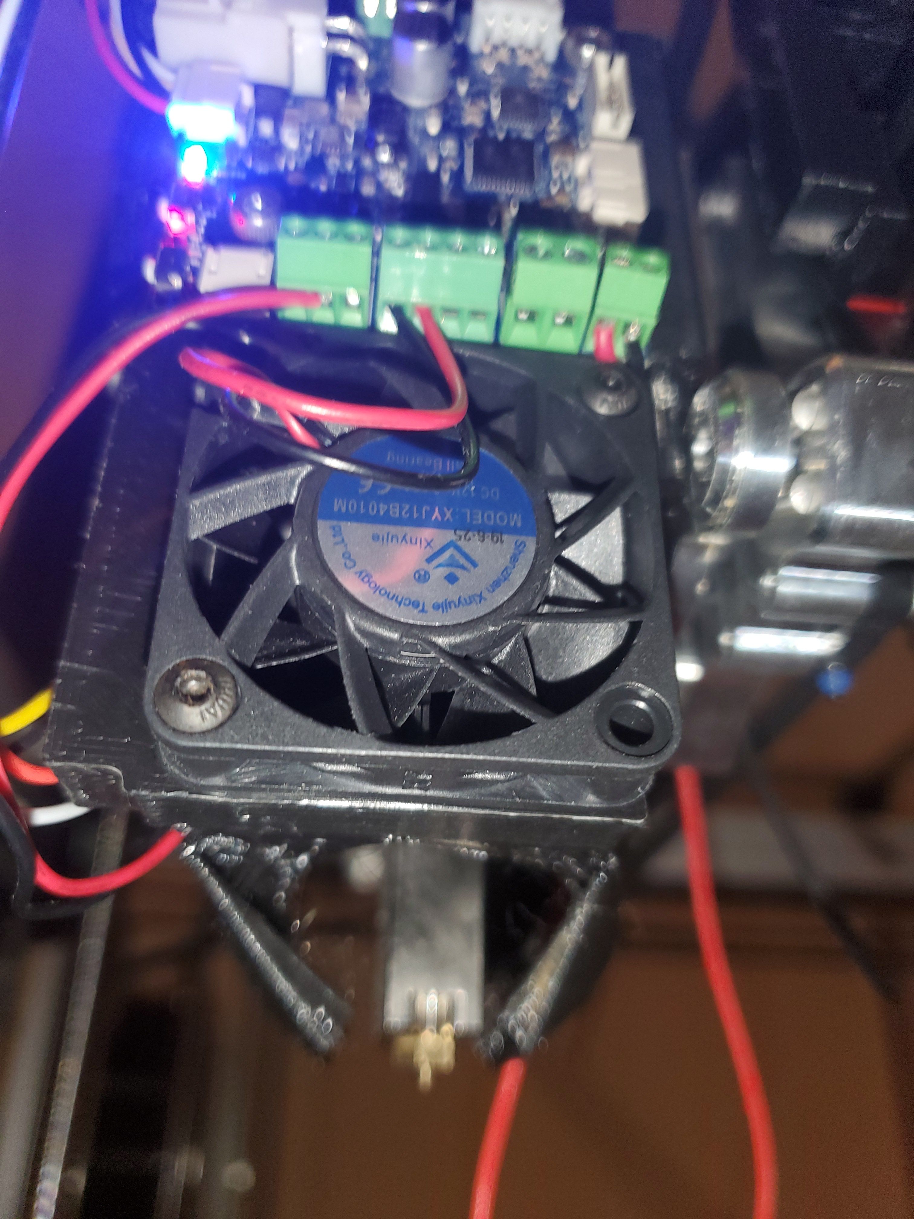
Hot end fan is running.
Print cooling fan is not running.
I can´t control both. -
How is the PT1000 connected?
Is it actually a PT1000?Photos of your toolboard wiring?
-
@phaedrux
It's the original tool changer thermistor.
Is it a pt100?
Oh no... -
-
@barbarossa-cologne

-
@barbarossa-cologne I've seen that crazy temperature value once before when a tool board was configured for a PT1000 sensor but the sensor wasn't connected.
-
@dc42 that's what I checked another time 2 minutes ago. It's definitely connected.
-
@barbarossa-cologne have you measured its resistance, to verify that it is a PT1000, not a PT100 or a thermistor?
-
@dc42 connected a different thermistor = same problem