zprobe cannot reach
-
@infidelprops okay, lets just go over this from the beginning.
Look at you printer with 0,0 in the front left corner, xmax to the right and ymax to the back. Where is the probe relative to the nozzle? Your config has it 47mm to the left and 10mm to the front of the nozzle. If that photo you posted is with the carriage at x=328mm, something here is wrong and we need to fix it.
Where are you endstops located physically? Your config has them at the low end (i.e. near 0,0, which should be the front, left of your printer) -
@engikeneer That's interesting indeed if 328 is the wrong location for my x-position in the previous photo.
Here's a phot of my printer and the endstop locations, relative to me facing the printer.
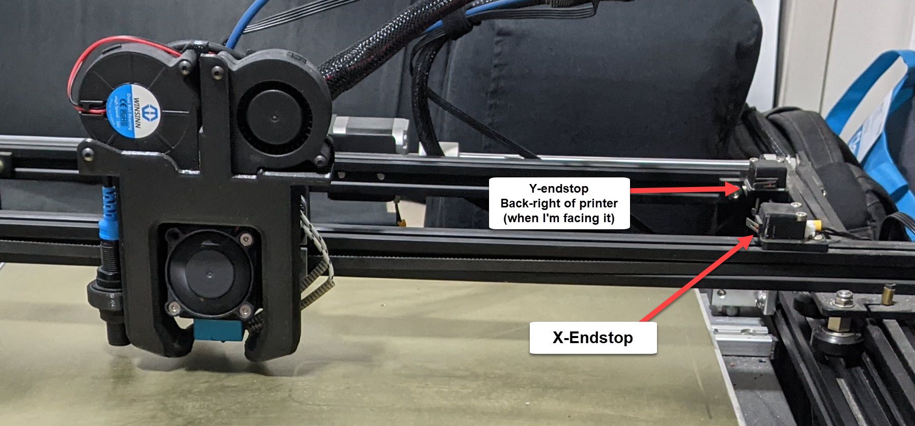
Here's my axis limits
; Axis Limits
M208 X15 Y15 Z-10 S1                                 ; set axis minima
M208 X350 Y350 Z400 S0                             ; set axis maxima
So X15 and Y15 is here:

And this is X328 and Y350:

-
@infidelprops all right, that makes more sense now. So, if you stand at the 'front left' of the printer (i.e. 0,0, i.e. sit on the arm of your sofa!), the probe has a +ve x and a +ve y offset, so you need to update your G31 offsets to match.
G31 P500 X47 Y10 Z3.919Now for your mesh grid. In x, the lowest position your probe can reach is x=47+15 = 62mm, and it can get right to the bed maximum (362mm?). In y, your probe can reach y=15+10=25mm up to the bed max (370mm?). Personally, I'd measure 1-2mm inside these limits just to be safe. I would also suggest you use the P parameter instead of the S parameter. This just splits it into 'P' points, rather than a bunch of points as spacing 'S'. For a detailed mesh you could go up to P20 (though it will take a while to probe!)
So based on all that and with your corrected G31 offsets, and proper M208 limits I'd suggest your mesh grid could be:; Axis Limits M208 X15 Y15 Z-10 S1 ; set axis minima M208 X362 Y370 Z400 S0 ; set axis maxima ;Mesh Grid M557 X63:361 Y26:369 P20 ; define mesh grid -
@engikeneer Thanks man, not sure why I have my axis's flipped, but that helps and make a lot more sense. and I just kicked off a print on my other printer and noticed that it does report 0,0 on the front-left, not like I have it configured here...
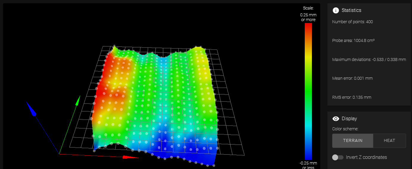
So I ran a mesh grid and I didn't lose any probe points, but my mesh and height map is allllll over the place. Really weird as before I put on this ABL, I had a BLT on the same bed and I dubbed this one my best printer because it always put down better layers. But looking at this heightmap, I just don't know what's going on here.
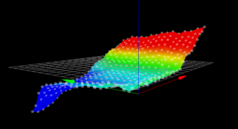
I've levelled the bed, use the paper on the springs and put a leveller on it to make sure, but is there something else I should be doing to help improve this height map? (Should I start a new thread with this question or just keep it here?)
Thanks again, big help!
-
@infidelprops
Is that a magnetic printing plate?
Edit:
It is....Check the mounting. Inductive probs are sensible to magnetic irregularities -
@diy-o-sphere Thanks mate, I have read it can cause problems... But how do I check the mounting? Is it the magnetic plate or the ABL mount?
-
I did some work on my springs and manual z-axis movement and getting better results... Going to keep trying working on these spring knobs and z-axis manual movements, re-measure z, probe and repeat
-
Ok... so this is a bit confusing when I set my axis min/max
I want my X/Y Max to be here:

Now, when I have M208 X0 Y0 Z-10 S1, the position of the above photo is X313 and Y355. When I jog my X and Y axis's, it stops here, which is perfect.But then I went to set my X/Y minimum, and this is where it gets weird and I'm sure I'm just not understanding how the coordinates are set. This is the position where I want my prints to be at minimum, which is X15 and Y15.

So I set M208 X15 Y15 Z-10 S1 and restart the printer.... BUT, now when I homeall, the printer reports X15 and Y15 as if it's 0,0 and it hits my end stops.

Is there a way to keep my board settings as X0,Y0 but my min printing area as X15,Y15?
And is there a way that I can flip the coordinates so that X0,Y0 is my front left as I'm not sure how I flipped that.
-
@infidelprops with low-end enstops (like you currently have configured), they simply set the x/y position to the axis minima from M208 when they are triggered. If they trigger when the head is off the bed, you can simply set the minima to be -ve (then 0,0 ends up at the corner of the bed). No matter what you do, you can always set up your slicer so that it 'thinks' the printer can't go outside a certain area, even though it can.
If you want to swap the coordinate system round, then the thinghs you would need to change are:
- endstops need to be set to high end (M574 X2 / Y2)
- update the Z-probe offsets (as the directions will be reversed)
- update all your homing files (homex, homey & homeall) so that the xy movement commands go in the opposite direction
- finally, update your M208 numbers so that you get 0,0 to be the front left corner of the bed (by changing the maxima values) and the min travel position (by changing the minima values). This may take a little trial & error
For an example, part of your homeall would change from:
G91                     ; relative positioning
G1 H2 Z5 F6000          ; lift Z relative to current position
G1 H1 X-355 Y-355 F6000 ; move quickly to X and Y axis endstops and stop there (first pass)
G1 H2 X5 Y5 F6000       ; go back a few mm
G1 H1 X-355 Y-355 F1800  ; move slowly to X and Y axis endstops once more (second pass)
G90                     ; absolute positioning
to...
G91                     ; relative positioning
G1 H2 Z5 F6000          ; lift Z relative to current position
G1 H1 X500 Y500 F6000 ; move quickly to X and Y axis endstops and stop there (first pass)
; note: I changed the value to 500 to make sure it will always get to the endstop, but you can drop it a bit to a more sensible value when you're set up
G1 H2 X-5 Y-5 F6000       ; go back a few mm
G1 H1 X355 Y355 F1800  ; move slowly to X and Y axis endstops once more (second pass)
G90                     ; absolute positioning
Hope that makes sense...

-
@engikeneer, @DIY-O-Sphere - thanks gents! I was able to get it back to how it should be, but it definitely took a lot of tweaking and trial/error.
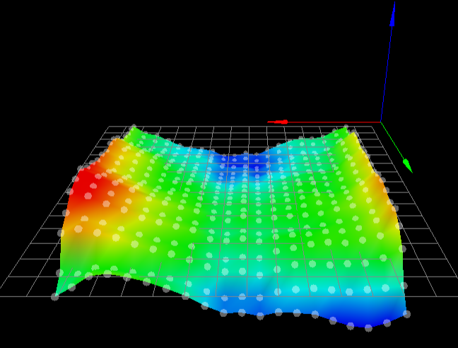
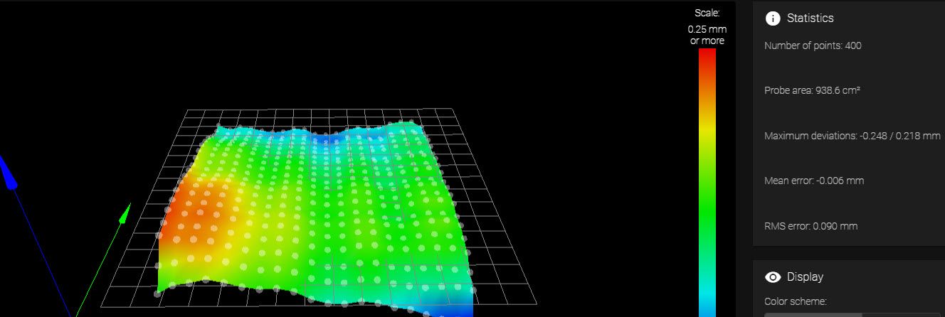
I've re-ran the mesh and while it's not a ski slope anymore, I still have some pretty big dips... Any thoughts on how best to get this more flat? I have a bed with 4 spring screws to tighten/loosen and I ran that
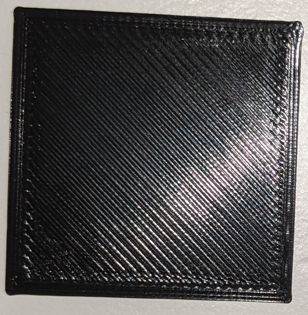
On the positive side... I've finally been able to print a bed levelling test and adjust the babysteps... Squares are coming out not bad, but not amazing. Will continue to test it all
-
@infidelprops one thing to bear in mind that is the heightmap of the bed measured from the nozzle at certain locations - i.e. the bumps & dips could come either from the bed not being flat, the x-gantry sagging, the two y-rails not being level, or any other thing with your frame/motion system.
Looking at it, I'd discount the massive dip in the front right. Quite likely thats come from the sensor going off the print surface a bit and giving some odd readings. I'd probably start your mesh from a bit further in. Same might go for the very left edge where it's quite high
In the y-direction your bed is raised in the middle - this kinda makes sense given that it's a flat plate supported in the middle at either side.
In the x-direction, the bed sags in the middle for the same reason. FYI, My heightmap is raised in the middle because the gantry is floppy and sags down.
The ridges running in the y-direction are interesting. Often ridges/ripples are due to backlash in the motion system (they'd go left to right as the print head changes direction for each pass across the bed when creatingthe map. However, in this case it can't be as they're going the wrong way. It could be some interference bwteeen the sensor and the magnetic plate like @DIY-O-Sphere suggested, or it could just be a distortion in the x-gantry rail where the wheels roll, or something completely different. Hard to tell.
Probably the easiest way to tell how good the heightmap is is to try printing things. If there's obvious issues with the first layer in certain parts of the bed, then you know which areas you're having problems with. You can always download the heightmap as a csv and manually tweak it in excel, then re-upload to DWC. I did this a bit when I was having troubles with my old piezo probe giving me odd readings. However, if your heightmap shows a dip in the middle, you might well have a dip in the middle!
Overall, most of your bed seems to be within +/-0.1mm which isn't too bad (mine is probably worse and gets good prints!). In an ideal world your bed would be mirror flat, your motion system perfectly rigid and you wouldn't even need a heightmap. But then again, if you wanted that you'd need 10x the budget and wouldn't be starting with an Ender5!
-
@engikeneer thanks mate, that's a really good download of knowledge! I have started to print the bed square level test with the 5 squares, and those print pretty well and as expected, a few better than others.
I did do quite a bit more tweaking and adjust the mesh grid as you suggested and I got a much better height map.
Just finished a level test and the center square was perfect... couldn't ask for a better first layer