InputShaping-Plugin-0.2.0-pre6 released
-
@mfs12 very interesting, I put this together today https://forum.duet3d.com/topic/25531/collecting-lis3dh-data-outside-of-rrf and this could be a nice integration to call into an external device to collect data and subsequently stream it into dwc/rrf (rather than M956 to initiate data collection, it would be instead a call to an http endpoint that would stream data to a file in /sys/accelerometer/...)
lots of work to be done, and I don't know if I necessarily want to take on the firmware work yet, but this could make for a nice seamless experience. @PCR, awesomely, has even offered to design a combined lis3dh&esp8266 board; that means data collection could work with just 2 wires, 3.3v and gnd.
-
@pfn, would be cool to have it run with a battery and now cables at all

Basically there are two modules to modules to modify
- configuration, how to reach the accelerometer
- recorder, howto to download the accelerometer data
Shouldn't be overly complicated. Altough it is nothing i want to take care of right now.
You can find the sources at
https://github.com/mfs12/DuetWebControl/tree/inputshaping-accel-plugin/src/plugins/InputShaping
-
@mfs12 I've been using the plugin to try and find the best setup for my printer and here are a few thoughts...
-
When testing an axis say X the test currently just uses whatever position the other axis happens to be in. I'm not sure this gives the best results. In particular if you are switching from testing x to y and back again (as the position at the end of the test may not be the best position for tests on the other axis). I wonder if either the test should choose say the mid point of the other axis or allow you to configure it? It seems to me that the magnitude of the resonance can vary depending upon the position to some extent. I think klipper has the notion of a test point for this purpose.
-
Do you have any idea how much the length of the test move and the end point impacts the test results? In particular does the final position of he print head change them? I've not tested this but I wonder if perhaps having the end point be in the centre of the printer may give better/different outputs? Again perhaps the notion of being able to set a test point might help here?
-
I notice that the plugin display the "integrals" for each axis, these seem to be useful when comparing different results to help choose a shaper or frequency. I assume that an automated process may make uses of these. It might also be of use to provide a total for all there axis (possibly selected by using the filter option so you just get the total for the visible results?).
-
The klipper test for this seems to move the head back and forth at different frequencies to try and identify different resonances rather than just using a single move, do you think this gives better results rather than just using a single move?
-
-
@gloomyandy re #4 only a single move is needed if the total time to decelerate is either much shorter than or several times longer than the period of any resonance, and the total move time is likewise long enough. If that condition isn't met, then moving at multiple speeds would be worthwhile.
Re #2 the point on the axis at which the deceleration occurs might affect the results, because the lengths of potentially resonating belt segments vary with position.
-
@mfs12 When I try to collect accelerometer data for my Y-Axis my Duet3 6HC crashes and reboots after doing the first two Y-Axis moves. Strangely, it works flawlessly on the X-Axis.
EDIT: After power cycling, it works again on both axis. I will keep an eye on this.

-
@gloomyandy, i a agree defining a test point does make sense. At least for cartesian printer's virbation should be worse when the axis are longer. Although this might also depend on your printer's architecture.
So i see here couple of "default" options which would make sense
- x and y
- center
- start
- end
- z
- center
- top
- bottom
So probably easiest way is to define the test point with all coordinates.
- x and y
-
@mfs12 said in InputShaping-Plugin-0.2.0-pre6 released:
So i see here couple of "default" options which would make sense
x and y
center
start
endIf I'm following correctly, I came here to suggest the same thing. As an example, for our 310mm x 310mm printer, I'd like to see the plug-in test the Y-axis at X0, X155, and X310 - and then overlay those results. Same for the X-axis.
We're doing this manually, and anything to help automate would be helpful.
Thanks
-
@mfs12 Amazing upgrade since the last version I tested, it’s a way more user-friendly!
I just started to use it and the experience is smoother, it’s definitively a more “finished” feature
I love being able to setup the multiple algorithms and run of them together.
A few things:
1- Name field in the configure tab is reset to “unknown” after having deleted the records - Don't know if this is on purpose, it just surprised me.
2- Adding the possibility to zoom-in the graph or select the frequency range would be nice
3- That one is probably not an easy one: better assignation of colors. It seems to cycle over 3 set of colors (record 0,3 6 has same colors; 1,4,7 the same and 2,5,8 the same again)
That's a graph I generated to compare quickly 2 frequencies against the 4 type of compensations.
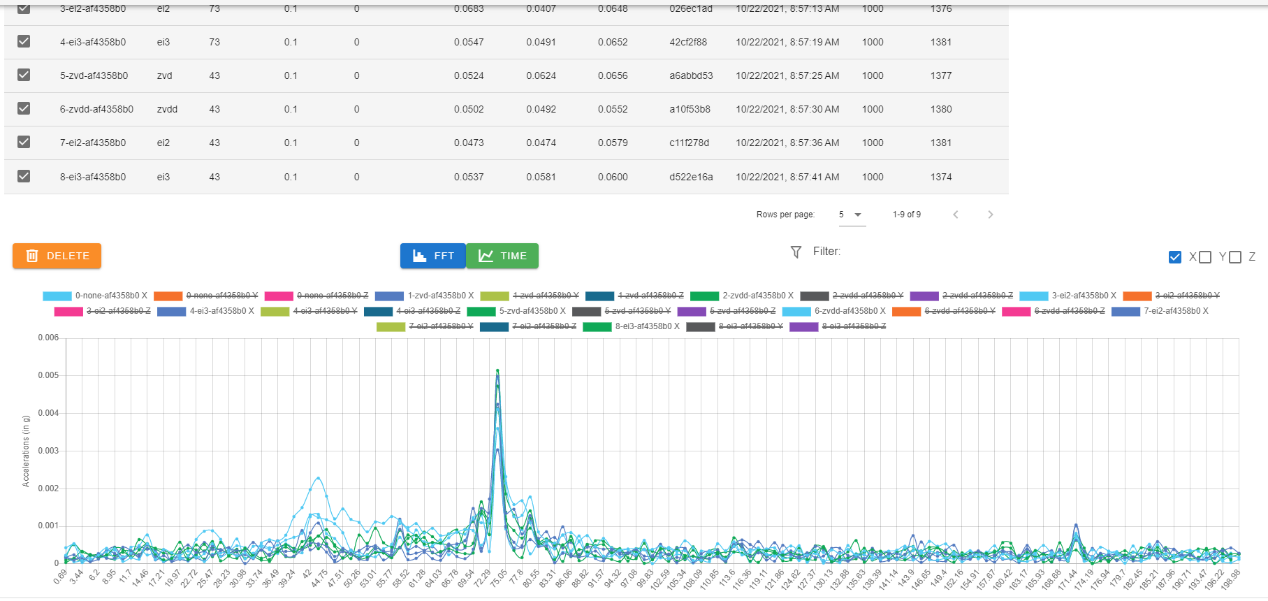
4- Being able to do a record with no move would be nice to capture the “default” machine vibration
5- It seems to have a validation like Start Position must be greater than Stop Position which prevent to do records with move going on the left
6- Can you confirm if the Start Position can be lower that 0 on a Delta? I cannot test it for the moment
7- Suggestion: Move the Delete button above the table with the records - the checkbox to select all is on the top.I'm impatient to see some of the items from the road map being implemented

-
What are the step to have this plugin appearing in DWC?
-
@zapta You need to uoload the plugin in DWC, go into "System" and "Upload System File"
When done, the plugin needs to be activated: go into "Machine-Specific" and "External Plugins" then click on the button to start it.
This plugin require to use RepRap Firmware 3.4.0-b5 and Duet Web Control 3.4.0-b5; both are beta versions.
-
Thanks @fred-y, I will give it a try. I do have the latest betas installed.
-
Hi All,
OK so I've never done this before, so be prepared for stupid questions and settings..!I've got my accelerometer working:-
M955 P0
Accelerometer 0:0 type LIS3DSH with orientation 20 samples at 1600Hz with 16-bit resolution, SPI frequency 2000000Configure settings:-
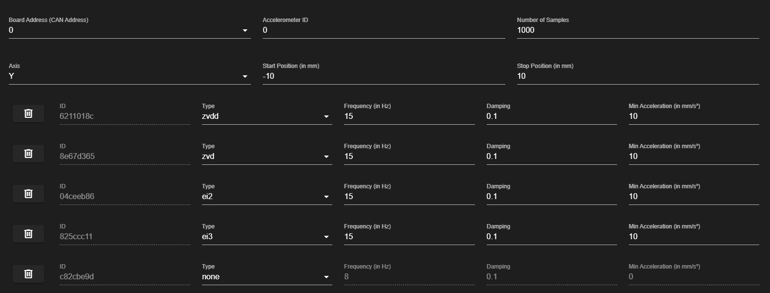
But when I press run noting happens, please note that the Y axis is driven by a can connected board at address 123, but the accelerometer is on io1 on my duet 3 Mini. I've used small accelerations and move distances because my printer is a polar machine, Y is the bed, and I'm not sure what its going to do in terms of move parameters (axis motor moves are in Deg not mm).
Also I'm not sure how to orientate the accelerometer as the y Axis goes round, so I've hopefully pointed the X axis of the chip to the bed centre and the Y axis circumferentially. Chip top is up and pointing in the direction of +ve z axis of the printer, text can be read normally looking towards the bed centre.
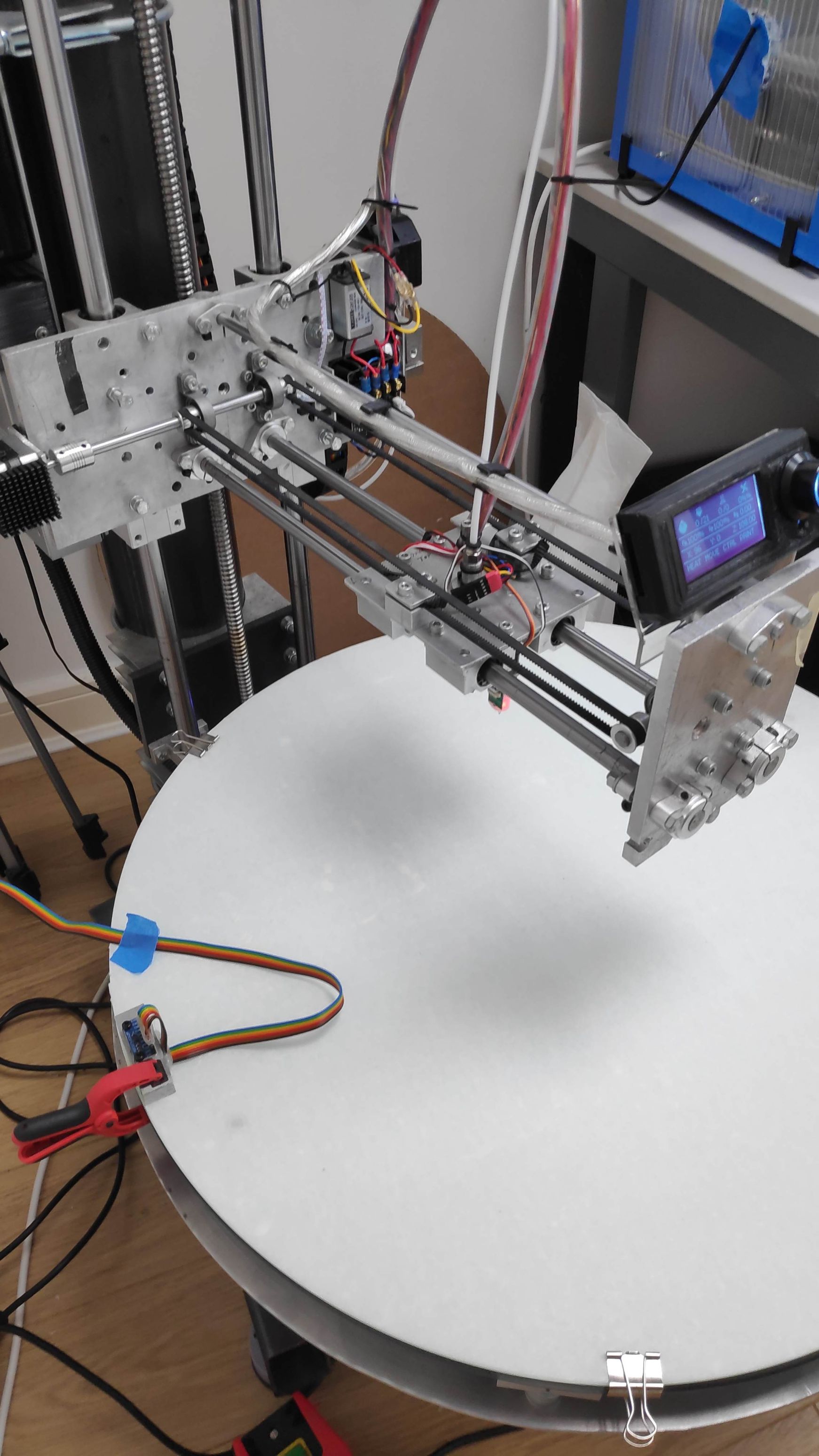
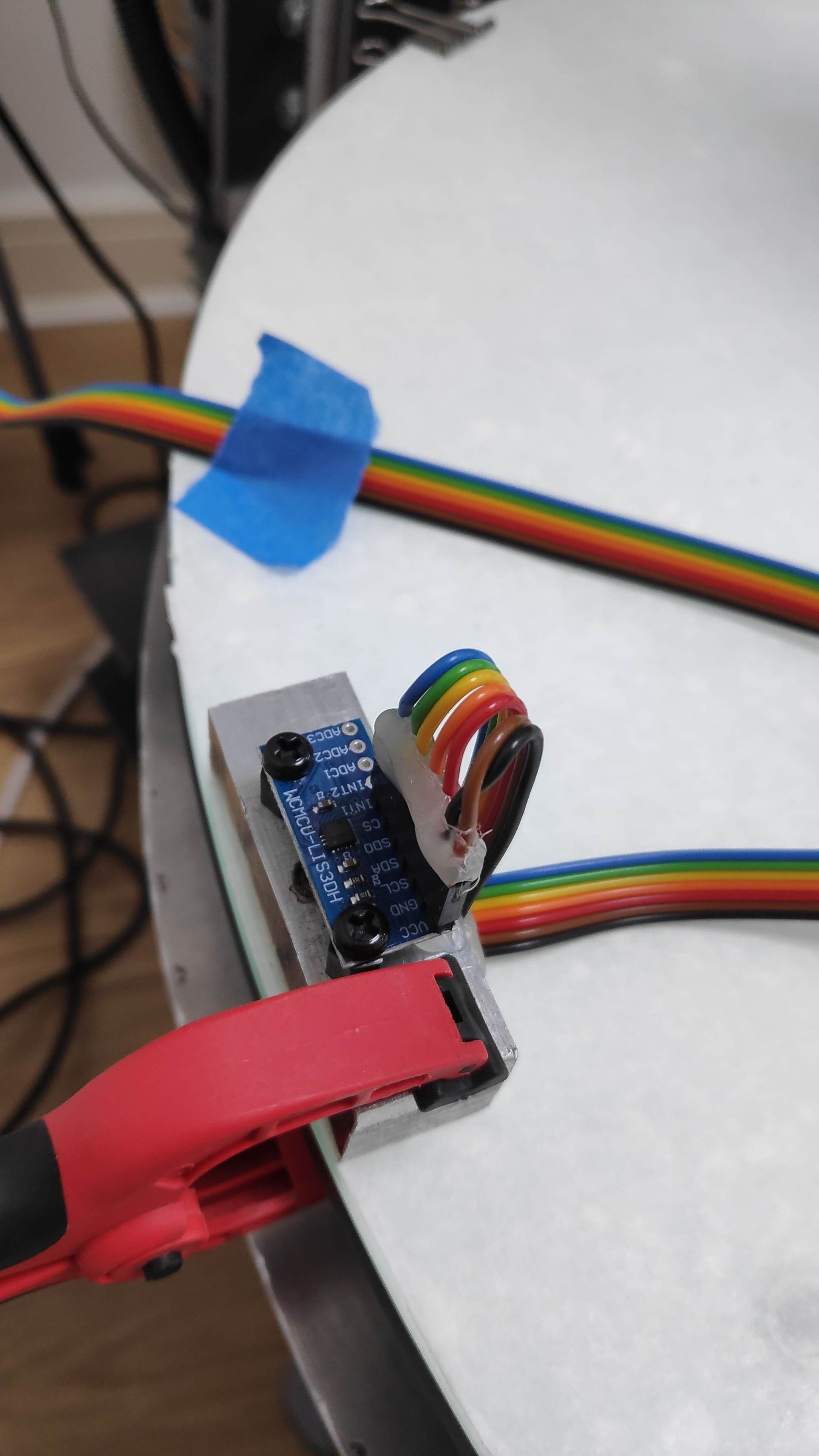
Please point out the obvious mistakes on my part, in the nicest possible way lol!

Many Thanks
Barry M -
- please the accelerometer configuration gcode.
And i think you should attach the accelerometer to the print head and not the baseplate. As most resonances will be in the moving parts.
-
@mfs12 said in InputShaping-Plugin-0.2.0-pre6 released:
- please the accelerometer configuration gcode.
And i think you should attach the accelerometer to the print head and not the baseplate. As most resonances will be in the moving parts.
Hi @mfs12
The code I used is: M955 P0 C"io1.out+io1.in"M955 P0 returns this in the console:
Accelerometer 0:0 type LIS3DSH with orientation 20 samples at 1600Hz with 16-bit resolution, SPI frequency 2000000The bed on a polar printer rotates, and this is the most significant source of vibration. Its effectively a bed slinger that rotates. The "Resonance" app on my android phone suggests that there are two significant frequencies, one at 17hz and one at 13hz.
Many Thanks
Barry M -
@cncmodeller did you home the printer and set the head at an appropriate position before you pressed Run? Are there any error messages on the console?
The plugin generates a move along the requested access that is within the bounds for that axis. You can adjust it when you create the session. Other axis positions are not changed. In your case, you need to ensure that the move generated by the plugin does not pass through the centre of the turntable. So if the centre is X0 Y0 and you are using the plugin to generate a X move, you must use an initial Y position sufficiently different from 0 to avoid the centre. Similarly, if you are using the plugin to generate a Y move, you must use an X position sufficiently different from 0.
In your particular case it would be beneficial for the plugin to generate a turntable-only move by using the H2 parameter and specifying start/end positions in degrees, however the plugin can't do that at present. You could temporarily change the M669 command in config.g to pretend your machine is Cartesian, set appropriate turntable limits using M208 and pretend-home using G92; then run the plugin.
One further point: input shaping does not work on segmented moves. This means that on a polar printer, input shaping cannot be applied to G1 moves. However, it should be applied to any G0 travel moves.
-
@dc42 thanks for the thoughts and obvious things to check, I followed your advice and all is well. As always the Duet team are more than helpful.
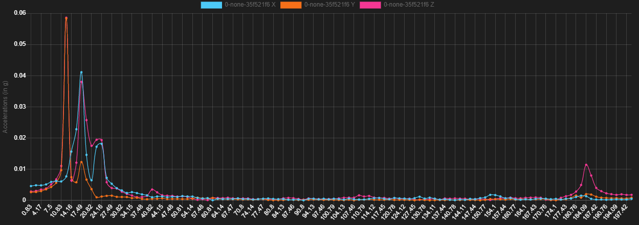
This isn't a clean bed move but the X axis is mechanically very distant from the bed so I don't think it matters. The move still results in a sharp jolt to the bed to excite the relevant modes.
That's interesting to know w.r.t. segmented moves, for peace of mind I need to check / make sure that the slicer uses G0 for travel moves as they are major contributors to the ringing I'm seeing at higher speeds.
Many thanks
Barry MEdit - PS does the plugin use G0 moves? I've only quickly tried a test with no shaping applied so far.
-
@mfs12 6HC w/PI4 1LC v1.1 Firmware 3.4-b5 on both.
M955 P121.0 I10 to set it up. Response: Accelerometer 121:0 with orientation 10 samples at 1344Hz with 10-bit resolutionConfigure board address (121), select X, zvd. When I hit run it homes, then nothing. Recorder State: HOMING
Reboot printer. If I home first, hit run and it doesn't respond. The state shows IDLE.
An uninstall/ reinstall has no effect.
-
@Stephen6309, can you share the browser's log and dwc's console log?
-
@mfs12 How do you get those logs?
-
in firefox you can open the browser's console "Ctrl-shift+j".
Then -> Right mouse button -> export log to file -> upload file here.DuetWebControl -> open menu (left top) -> open console -> open console's menu (right top of the messages) -> download as file -> upload here.
For further details:
Check and search for "download". https://duet3d.dozuki.com/Wiki/Duet_Web_Control_v2_and_v3_(DWC)_Manual#Section_Console
More details about firefox' console. https://developer.mozilla.org/en-US/docs/Tools/Browser_Console
-
 undefined mfs12 marked this topic as a regular topic