Feature Request - workpiece angle compensation CNC
-
@jay_s_uk @jrentschler01 it appears that G69 cancels any current coordinate rotation; however I can't find a precise definition for G68 because it isn't NIST-standard. Here are some questions:
- Is it acceptable to support rotation only in the XY plane? That's all Mach3 seems to support, although Fanuc supports rotation in any plane.
- If you have coordinate rotation in force and you issue a G17/18/19 command, what happens? Stop the job with an error? Or cancel the coordinate rotation?
- There appear to be two conventions about how to specify the coordinates of the centre of rotation. Fanuc uses the two coordinate letters depending on which plane is selected (e.g. X and Y). Mach3 always uses A and B. Any preference? Or should we support both?
- If I do an initial implementation, would you be able to test it? You would need to test: G0 G1 G2 G3, interaction with G17/18/19, and the reporting of the rotation in the object model.
Duet WiFi hardware designer and firmware engineer
Please do not ask me for Duet support via PM or email, use the forum
http://www.escher3d.com, https://miscsolutions.wordpress.com -
- I would be happy with just X and Y rotation.
- I have not yet made use of G17/18/19
- Both notations would be the best of both worlds but I don't know how easily that could be implemented
- Yes, I would be in a position to test this. I would of course have to ask @gloomyandy to provide me with a build as my CNC runs on an SKR Pro
-
@dc42 Yes the XY plane is all I need because if you want do somthing precise you need to know the exact position (with rotation) of the work piece in xy plane.
I don't really care wich command its neccesarry to use for it if we can acomplish it with G17 its fine. But it should be nothing that we have program in the Postprocessor bcs at this time we don't know how the workpiece will be at the table.
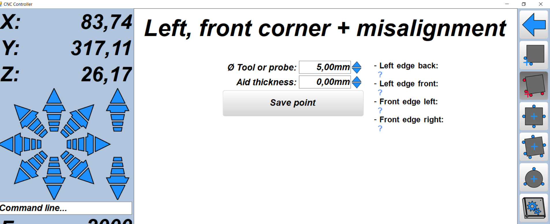
I used Estelcam as CNC conroller (and Fusion 360 for CAM) but right now I'm doing a upgrade with new electronics and I have a duet2 here that im going to hook up and it should be done by end of the week to run first tests. But I got concerned when I didn't find a method to input the workpiece rotation like I was able to do it in Estelcam:
Sure the edge probing could be done in a macro an the calculate the xy 0 and the rotation.
Do you think that's possible with G17? I would be able to test it.
-
@jrentschler01 let me know when you are ready to test this feature, then I will provide you with an internal build of RRF. Which Duet do you have?
Duet WiFi hardware designer and firmware engineer
Please do not ask me for Duet support via PM or email, use the forum
http://www.escher3d.com, https://miscsolutions.wordpress.com -
@dc42 duet2 wifi with fw 3.3
-
@jrentschler01 There is a test build here: https://www.dropbox.com/sh/xeu30go894p9xbs/AAB5U66SH4wbjKIcX0snUbKxa?dl=0
If you are not already running 3.4b5 please upgrade to that before upgrading to this (and check the upgrade notes).Note this is untested so proceed with caution.
-
@t3p3tony said in Feature Request - workpiece angle compensation CNC:
the
@T3P3Tony Thank you I'm close to start to test, wiring tooks a little longer but I hope I should have everthing running by tomorrow.
But how should be the procedure for the compensation? -
@jrentschler01 i've written a macro.
this in theory should work but I haven't tested it yet.var y_first_measurement = 0 var y_second_measurement = 0 var y_length = 0 var x_first_measurement = 0 var x_second_measurement = 0 var x_length = 0 var y_over_x = 0 var y_x_tan_rads = 0 var y_x_tan_deg = 0 M291 P"Put the probe on the left hand side of the bottom edge" S2 X1 Y1 Z1 ; Pop up box asking for operator input M558 F1500 ; Set the initial probing speed G38.2 Y600 P0 K0 ; Probe the material as a first pass G1 Y{move.axes[1].machinePosition-5} ; Move 5mm away from the material M558 F150 ; Set the final probing speed G38.2 Y600 P0 K0 ; Probe the material again M400 ; Make sure all movement is complete set var.y_first_measurement=move.axes[1].machinePosition ; Record the stop position y_first_measurement set var.x_first_measurement=move.axes[0].machinePosition ; Record the stop position x_first_measurement M400 ; Make sure all data recording is complete G1 Y{move.axes[1].machinePosition-5} ; Move 5mm away from the material G1 X{move.axes[0].machinePosition+50} ; Move along the workpiece in X M558 F1500 ; Set the initial probing speed G38.2 Y600 P0 K0 ; Probe the material as a first pass G1 Y{move.axes[1].machinePosition-5} ; Move 5mm away from the material M558 F150 ; Set the final probing speed G38.2 Y600 P0 K0 ; Probe the material again M400 ; Make sure all movement is complete set var.y_second_measurement=move.axes[1].machinePosition ; Record the stop position y_second_measurement set var.x_second_measurement=move.axes[0].machinePosition ; Record the stop position x_second_measurement M400 ; Make sure all data recording is complete set var.y_length={var.y_second_measurement-var.y_first_measurement} set var.x_length={var.x_second_measurement-var.x_first_measurement} set var.y_over_x={var.y_length/var.x_length} set var.y_x_tan_rads=atan(var.y_over_x) set var.y_x_tan_deg=degrees(var.y_x_tan_rads) G68 A0 B0 R{var.y_x_tan_deg}Now this will ask you to jog to the bottom edge of your material, ideally you should go to somewhere near the bottom left.
This is of course assuming you're using a probe that can probe in X, Y and Z and its set as K0. I use a vers.by probe.
It uses G38.2 and stores the X and Y coordinates of each point. Once it probes the first point, it moves 50mm in X and probes again.
The angle is then calculated and fed into G68.
If you don't want to set it that way, its set usingG68 Ax Bx Rxwhere Ax is the centre point to rotate around in X, Bx is the centre point to rotate around in Y and Rx is the angle to offset and is counterclockwiseOwns various duet boards and is the main wiki maintainer for the Teamgloomy LPC/STM32 port of RRF. Assume I'm running whatever the latest beta/stable build is
-
After days of reading through this forum I managed now to get my machine wokring somehow but there are still a lot off issues that i found with using the duet as CNC Controller. But I guess I should put this in a seperate thread, right?
@t3p3tony But now I was able to test the angle compensation, I was a little confused with the other threads that I thought you will do it differently then the G68 command that's why I asked for the procedure.
I tryed it with the RRF 3.4b5 in the link and the G68 command but it was a fail. Here is what I did:I drawed a simple rectangle with this G-Code
;simple rectangle for test
G90
G21

G1 F500
G1 X50
G1 Y50
G1 X0
G1 Y0
Then I just moved the X Work offset +70 and entered
G68 A0 B0 R45
and run the same G-Code again but the result was far away from what I expected: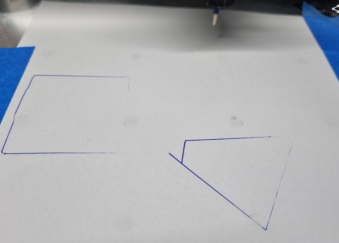
the left rectange is normal without G68 and the right one is with the 68.I think just the first move looks right with the 45° angle. What could be the Problem?
Jürgen
-
@jrentschler01 i am not sure, it will take me quite some time to get setup to test this right now so i wonder if @jay_s_uk has had a chance to test it and if its working for him?
-
@t3p3tony not had a chance to test it yet. I'll see if I can set something up later on
-
@jay_s_uk do you think you can help in this?
Let me know if you you guys need more information or anthing I should test.I knkow i needed quite some time to get ready but I'm not sure how long I keep this setup with the duet because this will be one of the essential functions I need and some other issues that I faced with using RepRap for CNC. I might moving on to linuxcnc soon.
-
@jrentschler01 maybe post about your other issues?
Owns various duet boards and is the main wiki maintainer for the Teamgloomy LPC/STM32 port of RRF. Assume I'm running whatever the latest beta/stable build is
-
@jrentschler01 I confirm, G68 is not working properly. I'm looking at it now.
Duet WiFi hardware designer and firmware engineer
Please do not ask me for Duet support via PM or email, use the forum
http://www.escher3d.com, https://miscsolutions.wordpress.com -
 undefined jrentschler01 referenced this topic
-
undefined jrentschler01 referenced this topic
-
undefined jrentschler01 referenced this topic
-
@jay_s_uk I did in a seperate thread:
https://forum.duet3d.com/topic/25848/found-issues-using-duet-as-cnc-controller -
@dc42 okay great let me know if I can do something to help
-
undefined jrentschler01 referenced this topic
-
@jrentschler01 please test G68 using one of the firmware binaries at https://www.dropbox.com/sh/4h5zqc0ki73wa9r/AABrMZxfMzMH4M0uJQPLsBmQa?dl=0.
Please note, these report the version as 3.4.0-beta6, however they are only candidates for the 3.4.0beta6 release. So please install the official beta6 when we release it.
I have tested basic G1, G2 and G3 moves with G68 and I believe they are working correctly. I have forbidden using G92 to set X or Y when G68 is in effect. I haven't taken account of G68 in any other situations - there may be some where RRF ought to.
The coordinate rotation defined by G68 is ignored when running system macros such as pause.g, resume.g, tool change and homing files.
Duet WiFi hardware designer and firmware engineer
Please do not ask me for Duet support via PM or email, use the forum
http://www.escher3d.com, https://miscsolutions.wordpress.com -
@dc42 I tested now with G1 the same wy with drawing a simple rectangle and it worked so far, I assume G2&G3 as well. Thank you a lot.
I'm continue getting a macro ready to probe the workpice and calulate the angle like @jay_s_uk mentioned.It would be great if we could visualize it after that somehow.
-
@jay_s_uk said in Feature Request - workpiece angle compensation CNC:
@jrentschler01 i've written a macro.
this in theory should work but I haven't tested it yet.var y_first_measurement = 0 var y_second_measurement = 0 var y_length = 0 var x_first_measurement = 0 var x_second_measurement = 0 var x_length = 0 var y_over_x = 0 var y_x_tan_rads = 0 var y_x_tan_deg = 0 M291 P"Put the probe on the left hand side of the bottom edge" S2 X1 Y1 Z1 ; Pop up box asking for operator input M558 F1500 ; Set the initial probing speed G38.2 Y600 P0 K0 ; Probe the material as a first pass G1 Y{move.axes[1].machinePosition-5} ; Move 5mm away from the material M558 F150 ; Set the final probing speed G38.2 Y600 P0 K0 ; Probe the material again M400 ; Make sure all movement is complete set var.y_first_measurement=move.axes[1].machinePosition ; Record the stop position y_first_measurement set var.x_first_measurement=move.axes[0].machinePosition ; Record the stop position x_first_measurement M400 ; Make sure all data recording is complete G1 Y{move.axes[1].machinePosition-5} ; Move 5mm away from the material G1 X{move.axes[0].machinePosition+50} ; Move along the workpiece in X M558 F1500 ; Set the initial probing speed G38.2 Y600 P0 K0 ; Probe the material as a first pass G1 Y{move.axes[1].machinePosition-5} ; Move 5mm away from the material M558 F150 ; Set the final probing speed G38.2 Y600 P0 K0 ; Probe the material again M400 ; Make sure all movement is complete set var.y_second_measurement=move.axes[1].machinePosition ; Record the stop position y_second_measurement set var.x_second_measurement=move.axes[0].machinePosition ; Record the stop position x_second_measurement M400 ; Make sure all data recording is complete set var.y_length={var.y_second_measurement-var.y_first_measurement} set var.x_length={var.x_second_measurement-var.x_first_measurement} set var.y_over_x={var.y_length/var.x_length} set var.y_x_tan_rads=atan(var.y_over_x) set var.var y_x_tan_rads = degrees{var.y_x_tan_rads} G68 A0 B0 R{var.y_x_tan_rads}Now this will ask you to jog to the bottom edge of your material, ideally you should go to somewhere near the bottom left.
This is of course assuming you're using a probe that can probe in X, Y and Z and its set as K0. I use a vers.by probe.
It uses G38.2 and stores the X and Y coordinates of each point. Once it probes the first point, it moves 50mm in X and probes again.
The angle is then calculated and fed into G68.
If you don't want to set it that way, its set usingG68 Ax Bx Rxwhere Ax is the centre point to rotate around in X, Bx is the centre point to rotate around in Y and Rx is the angle to offset and is counterclockwiseHello,
Very good job so far.
I still get an error while running the macro.
"M292
Error: in file macro line 37 column 13: meta command: expected '='
"
Can somebody help me? -
@CanDo415 Can you share your firmware version?